Abstract
In magnetic nanoparticle hyperthermia for cancer treatment, controlling the heat distribution and temperature elevations is an immense challenge in clinical applications. In this study we evaluate magnetic nanofluid transport and heat distribution induced by commercially available magnetic nanoparticles injected into the extracellular space of biological tissue using agarose gel with porous structures similar to human tissue. The nanofluid distribution in the gel is examined via digital images of the nanofluid spreading in the gel. A radio-frequency electromagnetic field is applied to the gel following the nanofluid injection and the initial rates of temperature rise at various locations are measured to obtain the specific absorption rate (SAR) distribution. By adjusting the gel concentration and injection flow rate, the results have demonstrated that a relatively low injection rate leads to a spherically shaped nanofluid distribution in the gels which is desirable for controlling temperature elevations. The SAR distribution shows that the nanoparticle distribution in the gel is not uniform with a high concentration of the nanoparticles close to the injection site. We believe that the experimental study is the first step towards providing guidance for designing better treatment protocol for future clinical applications.
Nomenclature
| A: | = | area (mm2) |
| cp: | = | specific heat (J/kg°C); |
| r: | = | radial distance (mm); |
| SAR: | = | specific absorption rate (kW/m3) |
| SLP: | = | specific loss power (kW/kg) |
| C: | = | nanoparticle concentration (kg/m3) |
| t: | = | time (s); |
| T: | = | temperature (°C); |
| V: | = | volume (ml); |
| Q: | = | heat generation distribution (kW/m3) |
| ρ: | = | density (kg/m3) |
| d: | = | distribution |
| i: | = | infused; |
| p: | = | pixel. |
Introduction
Magnetic nanoparticle hyperthermia has attracted growing research interests in malignant tumor treatment due to its simple implementation, low cost, and reduced complication. In this method, magnetic particles delivered to the tissue or blood vessels induce localized heating when exposed to an alternating magnetic field, leading to thermal damage to the tumor Citation[1]. Iron oxides magnetite Fe3O4 and maghemite γ-Fe2O3 nanoparticles are the most studied to date due to their biocompatibilty Citation[2]. When activated by an external alternating magnetic field, magnetic particles generate heat mainly due to the Néel relaxation mechanism and/or Brownian motion of the particles Citation[3],Citation[4]. Small particles (10–40 nm) are preferred in magnetic hyperthermia applications due to their ability to produce an impressive level of heating in relatively low magnetic fields Citation[5].
Two techniques are currently used to deliver magnetic particles to a tumor. The first is to deliver particles to the tumor vasculature Citation[6] through its supplying artery; however, this method is not effective for poorly perfused tumors. Furthermore, for a tumor with an irregular shape, inadequate nanoparticle distribution may cause under-dosage of heating in the tumor or overheating of the normal tissue. The second approach, which is the focus of the current study, is to directly inject magnetic particles into the extracellular space in tumors. This approach has been used to treat tumors in liver Citation[7] and breast Citation[7], Citation[8]. If the tumor has an irregular shape, multiple-site injections can be exploited to cover the entire target region.
In hyperthermia treatment, the distribution of temperature elevation is an important factor determining the therapeutic outcome. The quantification of heat generated by the particles Citation[3],Citation[9] has suggested that the size of an individual particle and properties of the magnetic field (strength and frequency) determine its heating capacity, defined as specific loss power (SLP). Given the SLP of the particles at a magnetic field strength and nanoparticle concentration distribution C(r), the distribution of heat generation Q can be computed as Q(r) = SLP × C(r). Clearly, the spatial distribution of the particle dispersed in tissue is an important factor determining the resulting temperature elevation. However, it is not clear how the spatial concentration of the particles in the tissue correlates with the particle concentration in the carrier solution before the injection. One previous study Citation[10] has measured the volumetric heat generation rate in an in vitro experiment. Doubling the particle concentration did not result in a 100% increase in the heat generation rate. The experimental data suggest that the particle concentration is not uniform after the injection. In addition, this study measured only the volumetric heat generation rate at one tissue location. Another experimental investigation by Hilger et al. Citation[8] showed that temperatures up to 71°C could be obtained at the center of a tumor in a mouse model. In the same study, the temperature elevation in dry breast tissues was determined and found to increase as a function of the amount of nanoparticles injected and magnetic field strength. The subsequent work by Johannsen and Jordan Citation[11–13] focused on testing the magnetic fluid hyperthermia on prostate cancer in human subjects. The histological analysis of the cancerous tissues showed a partial necrosis of the cells after the treatment. The previous experiments have demonstrated the feasibility of elevating the tumor temperature to a desired level; however, in some tumor regions, usually at the tumor periphery, under-dosage of heating (temperature increase lower than a critical value) was observed. In almost all the previous studies of the heating pattern using animal models, the temperature was measured at only one location in tissue. The actual spatial distribution of the magnetic particles after being injected into the tumor and the resulting temperature fields remain unknown in animal and clinical studies.
One challenge in assessing the energy generation induced in animal tissue is the technical difficulty of visualizing the nanofluid dispersion. Up to this date, gels are basically the only transparent porous materials that are equivalent to animal tissue for in vitro studies despite the fact that gels are homogeneous in comparison to the complicated tumor morphology. In fact, the tumor extracellular space convection/diffusion properties are found to be similar to the agarose gel Citation[14]. Ramanajuan et al. suggested a correction factor to account for the tumor tortuosity Citation[15]. Thus, agarose gel is a widely used alternative to animal tissue in the test of drug delivery in biological systems Citation[16–18]. Agarose gel with pore sizes in the range of 50 nm to 800 nm can be obtained by manipulating the agarose concentration and final solidification temperature Citation[17]. Chen et al. Citation[18] studied the transport of large molecular therapeutic agent in brain through infusing bromophenol blue dye in agarose gel. A reduced distribution volume was observed with increasing infusion flow rate.
Recently, magnetic particles diffusion in tissue was performed by studying their migration in gel in a steady magnetic field Citation[19–21]. Kalambur et al. performed a neat experimental study to characterize the movement and heating capacity of magnetic nanoparticles that are uniformly suspended in water, glycerol and collagen Citation[20] in a steady magnetic field as well as an alternating magnetic field. The particle concentration was also visualized through infra-red imaging. In a more recent study Citation[21], an experimental method was presented to study the interaction of magnetic nanoparticles with the solid gel matrix when subject to a magnetic force. It was found that ferroparticles aggregated and adhered to the solid structure of the gel when the particle diameter was higher than 135 nm. This would hinder the diffusion of the particles even in a very dilute gel. Despite the extensive research effort devoted to the magnetic nanoparticle diffusion in gel, to the authors’ knowledge, no research attempt has been made to address the spatial diffusion/convection mechanism of magnetic nanoparticle during and after the infusion of magnetic nanoparticles in a gel or tissue.
In mass transport during drug delivery, the induced drug concentration in the entire tumor should be large enough to kill tumor cells. It is well known that the high hydrostatic pressure in a tumor is the major barrier that prevents the drug from diffusing into the interstitial space. In heat transfer using nanoparticle heating, even if the nanoparticles are confined in the vicinity of the injecting site, heat can still be transferred via tissue conduction which is independent of the hydrostatic pressure in tumor. In clinical applications, a spherical-shaped nanoparticle dispersion in the tissue following the injection is preferred because it allows for controlled heat generation distribution. In the situation of treating an irregular-shaped tumor, multiple site injections of nanoparticles are needed to ensure that the temperature elevation in the entire tumor is sufficient to achieve tumor necrosis. However, the relationships among nanoparticle distribution, infusion flow rate, injection volume of nanofluid, and tissue structure are not well understood. It is difficult to devise a treatment protocol that enables the optimum distribution of temperature elevation in the tumor. Hence, it is important to quantify the nanoparticle distribution and heating pattern following the injection regarding the infusion flow rate and tissue properties. The objective of the current study is to investigate the diffusion and convection of a commercially available nanofluid in agarose gel with porosity mimicking that of different types of tissues. An idealized injection strategy was identified in the study for achieving a spherical shape of the nanofluid dispersion. The initial temperature rises at different locations were measured to determine the SAR values. A Gaussian expression of the SAR distribution was curve fitted based on the experimental measurements of the SAR.
Experimental methods and materials
Water-based ferrofluids (EMG705 series, Ferrotec (USA) Corporation, Nashua, NH) with a concentration of 3.3% by volume and a particle size of 10 nm were injected in agarose gel at different infusion flow rates. The agarose gel was prepared by dispersing agarose powder (Sigma-Aldrich, Saint-Louis, MO) in a 10% buffer solution (Tris-Borate EDTA, Gibco BRL, Rockville, MD) Citation[18]. The mixture was then heated until the agarose was completely dissolved. After being cooled at room temperature to 60°C, the solution was loaded into a transparent container and cooled further to room temperature (25°C) until solidification. The nanofluid distribution was studied in five agarose concentrations (0.2%, 0.5%, 1%, 2%, and 4%). Previous experimental studies showed that 3% and 4% agarose gel has a microstructure similar to hard tissue Citation[18], while the lower concentration gel has a porosity similar to soft tissue such as brain.
It was reported previously that the infusion flow rate and the catheter size should be relatively small to minimize the back-flow during the injection Citation[22–23]. Moreover, the experiments by Chen et al. showed that the catheter shape does not affect significantly the distribution volume Citation[18]. Therefore, a 26-gauge Hamilton needle (Fischer Scientific, Springfield, NJ) was used for injection through a protocol that minimizes the lateral motion of the needle upon insertion as well as the air gap between the needle and gel. A 1 cc syringe loaded with 0.3 cc of ferrofluid was placed on a syringe pump (Genie Plus, Kent Scientific, Inc. Torrington, CT) that enables precise control of the flow rate and the amount of the injection. The cylindrical container was pierced at its lateral surface and the needle was introduced through the gel. Once the infusion began at a preset flow rate, a digital camera (Canon A520) was used to acquire a sequence of digital images of the spreading of nanofluid in the gel. The top view pictures were taken at a constant distance from the compartment for all the experiments. illustrates the beginning of the spreading of the nanofluid inside the gel. It shows that the distribution is nearly axisymmetric around the needle.
Figure 1. The nanoparticles distribution inside the gel at the beginning of the injection: (a) side view, (b) top view.

For a given gel concentration and a constant ferrofluid volume (Vi = 0.3 cc), a relatively high infusion flow rate was selected initially. The flow rate was then reduced progressively until a relatively spherically shaped ferrofluid distribution was achieved. In this manner, we identified the maximum flow rate that produces a spherical nanofluid distribution. One experiment was performed for each of the given injection rate and gel concentration condition.
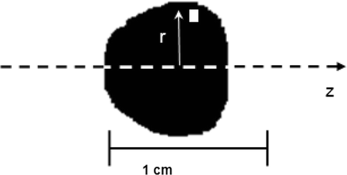
The images obtained by the digital camera were converted to a black and white version as displayed in using an image processing technique. The distribution volume Vd was calculated in the cylindrical coordinates using Equation 1:where Ω is the total black area in the image, dA is the pixel area, and r is the radial distance from the z axis to the pixel. The above integral was then evaluated numerically using the following equation:
where Ap = dA is the area of an individual pixel, p is the total number of the pixels in the black area. Ap and p were obtained from the Matlab® Image Processing toolbox.
Figure 2. A black and white version of the nanoparticles distribution for an infusion flow rate of 1.25 µl/min and a gel concentration of 4%.
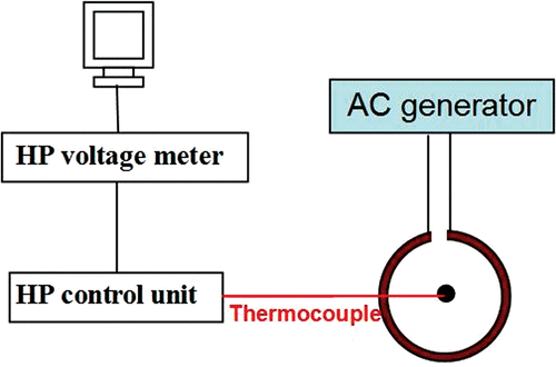
The gels with the almost circular shape of ferrofluid distribution were employed to perform the heating experiment. After removing the needle, the compartment was taped at the location of the needle piercing to prevent any liquid backflow. The compartment was placed inside a two-turn water cooled coil of 20 cm diameter and 7 cm height. The experimental set-up is shown schematically in . The compartment was positioned so that the injection site was located exactly at the center of the coil where the magnetic field strength reaches its maximum value (3 kA/m). In this region, it is reasonable to assume that the magnetic field is nearly uniform for two reasons. First, the dimensions of the obtained nanoparticles distribution (<10 mm diameter) are very small compared to the coil dimensions. Second, the nanoparticles were positioned at the center of the coil where the magnetic field is expected to be axisymmetric. Hence, the variation of the magnetic field in the radial direction around the nanoparticles is expected to be minimal.
A thermocouple was inserted in the gel vertically from the top surface using a systematic method for all the experimental conditions. Before the insertion, important geometrical parameters, including the gel volume, the compartment dimensions, and the needle tip position inside the compartment were measured. Thus the vertical distance from the injection site to the top surface of the gel can be calculated. This distance was then marked on the thermocouple to control the vertical translation of the thermocouple in the gel so that the tip of the thermocouple was located at the same depth beneath the top surface. The horizontal distance from the thermocouple to the needle tip was then measured. After connecting the coil to a radiofrequency generator (Hotshot 2, Ameritherm, Inc., Rochester, NY), an alternative current of 384 A at a frequency of 183 kHz was generated through the coil and a magnetic field was induced. The temperatures were recorded on a personal computer. In order to exclude the potential effect of heat induced by the thermocouple, we performed temperature measurements in the gel in the absence of nanoparticle injection using the same copper-constantan thermocouple. No temperature increase was observed once the radio-frequency generator was turned on. Hence, it was concluded that the heat generation in the thermocouple is negligible in this study.
Prior to each heating experiment, the gel compartment was kept at room temperature for 12 hours so that a uniform temperature can be reached throughout the gel. In the absence of any heat conduction in a medium, the volumetric heat generation rate, or the SAR, can be evaluated by the initial value of the transient term in the heat conduction equation:where ρ and cp are the density and specific heat of the gel, respectively Citation[24]. The initial slope of each curve was obtained by a linear fitting of the first five measurements of the heating curve. A minimum value of 93% for the R2 value was obtained for the curve fittings.
The measurements of the SAR at various gel locations were performed. For the SAR value at another gel location, the gel was allowed to cool down to establish a uniform temperature distribution before the heating was re-induced. At least four SAR values in the radial direction were obtained in each gel. It should be noted that no obvious nanofluid diffusion was observed after the infusion process. Thus the heating experiment can be repeated.
Results and discussions
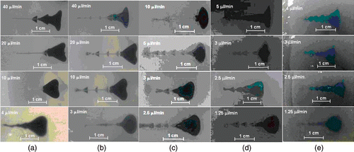
The shapes of the nanofluid distributions in the gel are displayed in for various combinations of the gel concentrations and flow rates. It has been shown that a higher gel concentration requires a smaller flow rate to achieve a nearly circular shape of the nanofluid dispersion. While a soft gel of 0.2% concentration allows a flow rate of 4 µl/min to produce a circular distribution, such a shape cannot be obtained in a hard gel (4% agarose concentration) until the infusion flow rate is reduced to 1.25 µl/min. The shape of the distribution tends to be more irregular with higher flow rates and higher gel concentrations as depicted in . This observation can be explained by several reasons. A low infusation flow rate and a large pore size make it easier for the nanoparticles to migrate in an isotropic manner in the gel to form a spherical distribution. On the other hand, in a gel with small pore size, a high infusion flow rate facilitates the nanoparticles to deposit on the solid structure in the direction of fluid flow, rendering some pores along the flow path inaccessible to the nanofluid. As a result, the nanofluid tends to migrate in the lateral direction, leading to the deviation from the circular shape. Further, the infusion of a fluid inside a gel induces swelling, i.e. internal deformation and dilatation Citation[22],Citation[25–27], due to the unique visco-elastic properties of gel Citation[28–29]. With an enhanced infusion flow rate, the pore deformation is more pronounced for a given gel structure as suggested by the theoretical investigations of Chen et al. Citation[22]. The deformation of the pore delays the relative motion of the fluid to the gel in the direction of the flow Citation[26]. Thus, nanofluid migration in the direction perpendicular to the flow dominates the nanofluid spreading in the gel.
Figure 4. The nanofluid distribution shapes for a gel concentration of (a) 0.2%, (b) 0.5%, (c) 1%, (d) 2% and (e) 4% for different infusion flow rates.
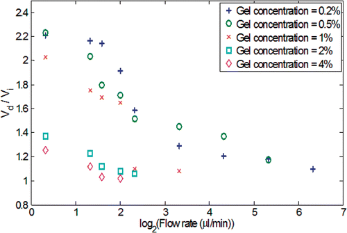
During the injection, the spreading of the nanofluid in the gel was quantified using a sequence of digital pictures acquired several times after the injection. The evolutions of the nanofluid distribution in the gel as a function of time are shown in . Since the gel has a porous structure, any injected liquid occupies a spatial volume, termed the distribution volume Vd, bigger than the infused volume of the liquid, Vi. shows the ratios of the distribution volume Vd to the infused volume Vi as a function of the gel concentration and the infusion flow rate at the end of the infusion. The gel with a higher agarose concentration (2–4%) exhibits a smaller distribution volume because the smaller pore size imposes a higher resistance to nanofluid transport in the porous structure. suggests that Vd/Vi reduces to a value close to unity at an infusion flow rate of 6 µl/min for the lowest gel concentration, and 2.5 µl/min for the highest gel concentration. This implies that above a certain threshold of infusion flow rate, the nanoparticles are confined in a restricted region in the gel without being able to diffuse freely. One attempted explanation for the smaller distribution volume at high injection rate is that the high flow rate facilitates the particles interaction with the solid matrix of the gel Citation[21], leading to their premature deposition and accumulation on the solid structure in a more restricted region around the injection site. A sharp drop of Vd/Vi from the 1% to 2% gel concentration is observed. This is because the decrease in the pore size of the gel at elevated gel concentration significantly limits the nanoparticle migration. Compared to the observation made by Chen et al. Citation[18], the Vd/Vi ratios obtained in this study are smaller than those obtained using bromophenol (Molecular Weight: 700 Da) solution. The deviation from the previous study can be explained by the difference in the size of the transported agents (nanoparticle versus Bromophenol molecule). The larger size of the nanoparticles (10 nm diameter ∼1500 kDa) used in the current study impedes their migration in the gel, and thus results in a smaller distribution volume. The ratio Vd/Vi can be used as a guidance for physicians in clinical applications to select judiciously the quantity and infusion rate of nanofluid according to the volume and structure of a given tumor tissue.
Figure 5. The calculated nanofluid distribution volume in the gel after the injection of 0.3 cc ferrofluid as a function of time during the infusion process.
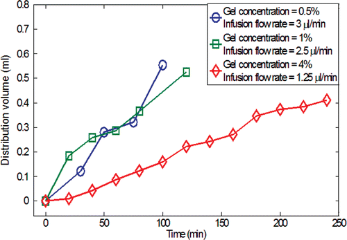
Figure 6. The ratio of the distribution volume to the infused volume of ferrofluid as a function of the infusion flow rate for different gel concentrations.
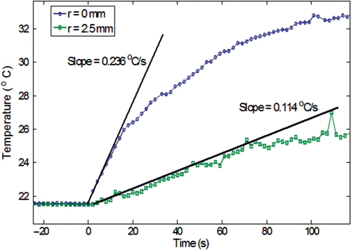
The temperature elevations in the gel induced by the injected nanoparticles when exposed to the external electromagnetic field were recorded at various locations as a function of time. Since the nanoparticles are the only heating sources present in the gel, the SAR distribution can be used as an index for the particle concentration in the gel. The initial temperature rises at two gel locations are illustrated in for a gel concentration of 0.2% and an infusation rate of 4 µl/min. Note that the initial temperature rises are almost linear, implying negligible heat conduction when the heating is turned on. The slope then becomes less steep due to heat conduction in the gel.
Figure 7. The evaluation of the initial slope of the heating curve for a gel concentration of 0.2% and an infusion rate of 4 µl/min (r is the radial distance from the injection site).
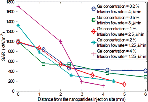
The slopes of the initial temperature curve at various spatial locations are used to determine the SAR values based on Equation 3. As shown in , the SAR decreases with the radial distance from the injection site, leading to a conclusion that more nanoparticles are deposited near the injection site. The higher gel concentrations (2% and 4%) result in a maximum SAR value much greater than that from lower gel concentrations (0.2%, 0.5%, and 1%). This observation suggests expedited particle transport from the injection site in the gel with low concentration. The different behaviors of the nanoparticle transport in the gel can be explained by the interaction between the nanofluid and solid gel microstructure. It was suggested by Nicholson et al. Citation[30] that as fluid/solute is infused inside a gel, either both the fluid and the solute directly propagates in the gel pores, or a small cavity of more concentrated fluid forms. The diffusion-convection mechanism is initiated afterwards. The cavity is more likely to form in a highly concentrated gel, i.e. hard gel, because of the small pore size and the enhanced mechanical strength. Thus, it is not surprising that in the gels of high concentrations, nanoparticles are mainly confined in a region close to the injection site. The concentration of the nanoparticles can then be easily evaluated as the ratio of the SAR to the specific loss power SLP of the pure ferrofluid Citation[3],Citation[4].
Figure 8. The specific absorption rate (SAR) as a function of the radial distance from the nanoparticles injection site.
Although any expressions can be proposed for the SAR distribution, it should result in a good fit to the experimental data. Based on the values of SAR shown in a Gaussian distribution is proposed for the SAR distribution:where r is the radial distance from the injection site, r0 is a parameter (in mm) which determines how far the diffusion occurs, and B determines the maximum strength of the SAR value (W/m3) at the injection site. The parameter r0 encompasses the effects of the injection rate and the gel concentration, two important factors that substantially influence the spatial distribution of the nanoparticles as stated earlier. The least residual curve fitting coefficients are shown in . As expected, r0 decreases as a function of the increased gel concentration, implying that the particle diffusion distance is limited to a smaller region surrounding the injection site. The maximum strength of the SAR is getting larger when the gel concentration is increased. The fitted expression of the SAR distribution can be used in future theoretical simulations to study the temperature elevations during nanoparticle hyperthermia.
Table I. Calculated curve fitting coefficients based on Equation 4 (R2 ≥ 98%).
Conclusion
The magnetic nanofluid transport in the extracellular space of agarose gel with porosities that mimic different types of tissue is investigated. The SAR distribution in the gel induced by the magnetic nanoparticle in an alternative electromagnetic field is characterized. Through tuning the infusion flow rate according to the gel concentration, the experimental results demonstrate the feasibility of obtaining a spherically shaped nanofluid distribution in the agarose gel that allows for controlled heating pattern in tissue. A higher SAR measured near the injection site implies more nanoparticles deposited in the vicinity of the injection site. The information acquired in this study regarding infusion flow rate and spreading volume of the injected nanofluid are imperative for the design of the injection sites and injection rate. Future studies will assess the effect of the blood flow rate in animal tissue on the nanoparticle distribution and heat generation through in vivo animal experiments. The effects of nanoparticle coating and PH value of the environment on nanoparticle deposition will also be examined. Based on the SAR distribution obtained in this study, a theoretical model will be developed to simulate the temperature elevation in tumor to provide an optimized protocol for future clinical applications.
Acknowledgements
This research was supported in parts by an NSF grant CBET-0730732 and an UMBC DRIF grant. The research is performed in partial fulfillment of the requirements for the PhD Degree from University of Maryland Baltimore County by Maher Salloum.
References
- Gilchrist RK, Medal R, Shorey WD, Hanselman RC, Parrott JC, Taylor CB. Selective inductive heating of lymph nodes. Ann Surg 1957; 146: 596–606
- Moroz P, Jones SK, Gray BN. Magnetically mediated hyperthermia: Current status and future directions. Int J Hyperthermia 2002; 18: 267–284
- Hergt R, Andra W, d’Ambly CG, Hilger I, Kaiser WA, Richter U, Schmidt H. Physical limits of hyperthermia using magnetite fine particles. IEEE T Magn 1998; 34: 3745–3754
- Rosensweig RE. Heating magnetic fluid with alternating magnetic field. J Magn Magn Mater 2002; 252: 370–374
- Lv Y, Deng Z, Liu J. 3-D numerical study on the induced heating effects of embedded micro/nanoparticles on human body subject to external medical electromagnetic field. IEEE T Nanobiosci 2005; 4: 284–294
- Matsuki H, Yanada T. Temperature sensitive amorphous magnetic flakes for intra-tissue hyperthermia. Mater Sci Eng 1994; A181/A182: 1366–1368
- Hilger I, Hergt R, Kaiser WA. Towards breast cancer treatment by magnetic heating. J Magn Magn Mater 2005; 293: 314–319
- Hilger I, Andra W, Hergt R, Hiergeist R, Schubert H, Kaiser WA. Electromagnetic heating of breast tumors in interventional radiology: In vitro and in vivo studies in human cadavers and mice. Radiology 2001; 218: 570–575
- Hergt R, Hiergeist R, Zeisberger M, Glockl G, Weitschies W, Ramirez LP, Hilger I, Kaiser WA. Enhancement of AC-losses of magnetic nanoparticles for heating applications. J Magn Magn Mater 2004; 280: 358–368
- Masuko Y, Tazawa K, Viroonchatapan E, Takemori S, Shimizu T, Fujimaki M, Nagae H, Sato H, Horikoshi I. Possibility of thermosensitive magnetoliposomes as a new agent for electromagnetic induced hyperthermia. Biol Pharm Bull 1995; 18: 1802–1804
- Johannsen M, Gneveckow U, Eckelt L, Feussner A, Waldofner N, Scholz R, Deger S, Wust P, Loening SA, Jordan A. Clinical hyperthermia of prostate cancer using magnetic nanoparticles: Presentation of a new interstitial technique. Int J Hyperthermia 2005; 21: 637–647
- Johannsen M, Thiesen B, Jordan A, Taymoorian K, Gneveckow U, Waldofner N, Scholz R, Koch M, Lein M, Jung K. Magnetic fluid hyperthermia (MFH) reduces prostate cancer growth in the orthotopic Dunning R3327 rat model. Prostate 2005; 64: 283–292
- Jordan A, Scholz R, Maier-Hauff K, Van Landeghem FK, Waldoefner N, Teichgraeber U, Pinkernelle J, Bruhn H, Neumann F, Thiesen B, et al. The effect of thermotherapy using magnetic nanoparticles on rat malignant glioma. J Neuro-Oncol 2006; 78: 7–14
- Jain RK. Transport of molecules, particles, and cells in solid tumors. Annual Rev Biomed Eng 1999; 1: 241–263
- Ramanujan S, Pluen A, McKee TD, Brown ED, Boucher Y, Jain RK. Diffusion and convection in collagen gels: Implications for transport in the tumor interstitium. Biophys J 2002; 83: 1650–1660
- Khaled A, Vafai K. The role of porous media in flow and heat transfer in biological tissues. Int J Heat Mass Tran 2005; 46: 4989–5003
- Narayanan J, Xiong JY, Liu XY. Determination of agarose gel pore size: Absorbance measurements vis a vis other techniques. J Phys Conf Ser 2006; 28: 83–86
- Chen ZJ, Broaddus WC, Viswanathan RR, Raghavan R, Gillies GT. Intraparenchymal drug delivery via positive-pressure infusion: Experimental and modeling studies of poroelasticity in brain phantom gels. IEEE T Bio-Med Eng 2002; 6: 85–96
- Holligan DL, Gilles GT, Dailey JP. Magnetic guidance of ferrofluidic nanoparticles in an in vitro model of intraocular retinal repair. Nanotechnology 2003; 14: 661–666
- Kalambur VS, Han B, Hammer BE, Shield TJ, Bischof JC. In vitro characterization of movement, heating and visualization of magnetic nanoparticles for biomedical applications. Nanotechnology 2005; 16: 1221–1233
- Kuhn SJ, Hallahan DE, Giorgio TD. Characterization of superparamagnetic nanoparticle interactions with extracellular matrix in an in vitro system. Ann Biomed Eng 2006; 34: 51–58
- Chen MY, Lonser RR, Morrison PF, Governale LS, Oldfield EH. Variables affecting convection-enhanced delivery to the striatum: A systematic examination of rate of infusion, cannula size, infusate concentration, and tissue-cannula sealing time. J Neurosurg 1999; 90: 315–320
- Prabhu SS, Broaddus WC, Gillies GT, Loudon WG, Chen ZJ, Smith B. Distribution of macromolecular dyes in brain using positive pressure infusion: A model for direct controlled delivery of therapeutic agents. Surg Neurol 1998; 50: 367–375
- Zhu L, Xu LX, Chencinski N. Quantification of the 3-D electromagnetic power absorption rate in tissue during transurethral prostatic microwave thermotherapy using heat transfer model. IEEE T Bio-Med Eng 1998; 45: 1163–1172
- Barry SI, Aldis GK. Flow-induced deformation from pressurized cavities in absorbing porous tissues. B Math Biol 1992; 54: 77–997
- Basser PJ. Interstitial pressure, volume, and flow during infusion into brain tissue. Microvasc Res 1992; 44: 143–165
- Netti PA, Travascio F, Jain RK. Coupled macromolecular transport and gel mechanics: Poroviscoelastic approach. AIChE J 2003; 9: 1580–1596
- Johnson DL. Elastodynamics of gels. J Chem Phys 1982; 7: 1531–1540
- Tanaka Y, Fillmore DJ. Kinetics of swelling of gels. J Chem Phys 1979; 70: 1214–1218
- Nicholson C. Diffusion from an injected volume of a substance in brain tissue with arbitrary volume fraction and tortuosity. Brain Res 1985; 333: 325–329
