Abstract
Purpose: To evaluate the feasibility of concurrent treatment with the scanning ultrasound reflector linear array system (SURLAS) and helical tomotherapy (HT) intensity modulated radiation therapy (IMRT).
Methods: The SURLAS was placed on a RANDO phantom simulating a patient with superficial or deep recurrent breast cancer. A megavoltage CT (MVCT) of the phantom with and without the SURLAS was obtained in the HT system. MVCT images with the SURLAS were obtained for two configurations: (1) with the SURLAS's long axis parallel and (2) perpendicular to the longitudinal axis of the phantom. The MVCT simulation data set was then transferred to a radiation therapy planning station. Organs at risk (OAR) were contoured including the lungs, heart, abdomen and spinal cord. The metallic parts of the SURLAS were contoured as well and constraints were assigned to completely or directionally block radiation through them. The MVCT simulation data set and regions of interest (ROI) files were subsequently transferred to the HT planning station. Several HT plans were obtained with optimization parameters that are usually used in the clinic. For comparison purposes, planning was also performed without the SURLAS on the phantom.
Results: All plans with the SURLAS on the phantom showed adequate dose covering 95% of the planning target volume (PTV D95%), average dose and coefficient of variation of the planning target volume (PTV) dose distribution regardless of the SURLAS's orientation with respect to the RANDO phantom. Likewise, all OAR showed clinically acceptable dose values. Spatial dose distributions and dose-volume histogram (DVH) evaluation showed negligible plan degradation due to the presence of the SURLAS. Beam-on time varied depending on the selected optimization parameters.
Conclusion: From the perspective of the radiation dosage, concurrent treatment with the SURLAS and HT IMRT is feasible as demonstrated by the obtained clinically acceptable treatment plans. In addition, proper orientation of the SURLAS may be of benefit in reducing dose to organs at risk in some cases.
Introduction
Phase III trials comparing radiotherapy alone versus sequential radiotherapy and hyperthermia have shown the positive impact of hyperthermia on local control and in some cases overall survival for various tumor sites Citation[1–11]. Hyperthermia tumor cyto-toxicity is due to sustained temperatures above 42.5°C Citation[12], Citation[13] and to increased oxygenation and thermal radio-sensitization at lower temperatures Citation[14–16]. However, it is clinically difficult to achieve uniform temperature distributions above 42.5°C for protracted periods of time. At lower temperatures laboratory and clinical data support the use of concomitant thermoradiotherapy. In this scenario outcome is improved due to maximization of thermal radiosensitization Citation[17–19]. Phase I/II thermoradiotherapy clinical trials using a commercial hyperthermia system adapted to operate concurrently with a linear accelerator have shown the clinical feasibility of this approach with encouraging preliminary clinical results Citation[20]. These efforts motivated the development of the scanning ultrasound reflector linear array system, a hyperthermia device specifically designed and developed for simultaneous thermoradiotherapy using a linear accelerator Citation[21].
Helical tomotherapy is a technology based on the combined principles of a linear accelerator and computed tomography principles allowing daily targeting of IMRT using megavoltage CT guidance.
In this paper we present the feasibility of concurrent treatment with the SURLAS and helical tomotherapy IMRT.
Methods and materials
SURLAS
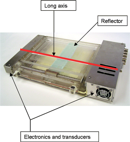
The basic design of the SURLAS was reported in the literature by Moros et al. Citation[22]. Briefly, the applicator consists of two parallel opposed ultrasound linear arrays aiming their acoustic beams to a v-shaped scanning ultrasound reflector. The reflector deflects the beams coming from opposite directions toward the treatment area. The reciprocating motion of the reflector in between the arrays allows for control of the energy spread over the scanned area. The description of several other key features of the SURLAS has also been reported Citation[19], Citation[22–27]. Radiologically, the SURLAS represents a block of near water density with some high density components that need to be avoided by the radiation beams. shows a photograph of the SURLAS with labeling of some of its major components including the device's long axis. The long axis of the SURLAS is used in this paper as a reference for how the device is oriented on the phantom.
Figure 1. Photograph of the SURLAS showing its long axis (red line along the scanning direction of the reflector) as well as some of its major components. The long axis is used as a reference on how the SURLAS is placed on the phantom with respect to the phantom's longitudinal axis.
Helical tomotherapy
HT systems (Tomotherapy Inc., Madison, WI) consist of a 6-MV linear accelerator mounted on a ring gantry in a CT scanner configuration Citation[28–30]. Opposite to the linear accelerator is an array of Xenon detectors used to obtain data for reconstructing MVCT images. The beam in a HT system is collimated by a pneumatically driven binary multi-leaf collimator that produces a fan beam with a maximum width of 5 cm along the patient's longitudinal axis and a length of 40 cm transversely at iso-center. Patients are positioned on the treatment couch that moves through the ring gantry while the gantry is rotating. The HT system is capable of treatment delivery and acquisition of MVCT images with clinically useful image quality and resolution for daily image-guided radiation therapy (IGRT). By taking a MVCT scan before each treatment, clinicians are able to verify the patient's anatomy, including the location of the tumor and critical structures with respect to the planned dose distributions. The alignment of the treatment planning CT with the MVCT allows for quickly repositioning of the patient to account for any inter-fraction changes in the patient's anatomy or position Citation[31–33]. The MVCT to treatment planning CT registration can be indexed to any fixed internal structure, such as bony landmarks, rather than to external skin markings as is currently done in conventional linac-based delivery.
Phantom studies for MVCT density table
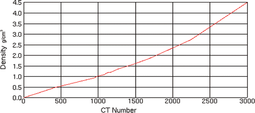
In order to obtain a satisfactory CT planning data set it was decided to use MVCT images for planning. One great advantage of MVCT is the absence of imaging artifacts produced by high density metals that are commonly seen in kilo-voltage CT (KVCT) images (see ). To perform accurate treatment planning dose calculations on a MVCT data set, a new MVCT value to density table was created. A tissue characterization phantom GAMMEX 467 (GAMMEX RMI, Middleton, WI) was scanned in a helical tomotherapy unit using a lower energy (3.5MV) imaging fan beam. The images obtained were then transferred to the Pinnacle Planning Station (Philips Medical Systems, version 8.0d, Bothell, WA) where MVCT Hounsfield and electron density values of various tissues were correlated into a density table (see ). This table was used for each treatment plan for accurate heterogeneous radiation dose calculation.
Figure 2. Kilovoltage and megavoltage CT images of the phantom with the SURLAS in place at approximately the same anatomical level. Please note the resolution of the MVCT image which has good soft tissue contrast as compared to the KVCT image. The KVCT image is degraded by artifacts specifically in regions near the high density materials of the SURLAS.
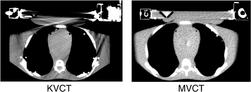
Figure 3. Megavoltage (MVCT) density table applied to each of the treatment plans. This table is specifically for the helical tomotherapy planning station.
RANDO phantom and regions of interest
HT MVCT of 3.5 MV energy images of a RANDO phantom (CIRS Inc., Norfolk, VA) with and without the SURLAS positioned on the phantom's chest were obtained in the normal scanning mode (2–4 mm pixel size) and 4mm slice thickness. Organs at risk and targets were contoured into the MVCT data set utilizing the Pinnacle Planning Station (Philips Medical Systems, version 8.0d, Bothell, WA). In the MVCT with the SURLAS, two tumor cases were considered. The first consisted of a superficial planning target volume (PTV) with maximum dimensions of 1 cm deep by 11.5 cm wide by 11 cm long. The second consisted of a deep PTV with maximum dimensions of 4 cm deep by 7.2 cm wide by 9.6 cm long. Both targets are in the region of the lower chest/upper abdominal walls mimicking a chest wall recurrence from breast cancer. The size of the PTVs was chosen to simulate difficult treatment scenarios for superficial extensive diffuse disease and a large bulky tumor. The lungs, heart, spinal cord and abdomen were outlined as OAR. In the SURLAS, the principal high density materials were outlined (scanning mechanism, lead screw, right and left end-plates and casings covering the main electrical components).
HT planning station
MVCT simulation data set, with a pixel size of 256 × 256, and regions of interest (ROI) files were transferred to the HT planning station (v. 2.2.2.33) via the DICOM-RT protocol. The dose optimization was guided using several user selected parameters which have been described in the literature Citation[34]. These parameters are the jaw width or thickness of the treatment field at the machine iso-center, pitch or couch travel per gantry rotation divided by jaw width and modulation factor or range of leaf intensity values allowed in the optimized plan. The details of the inverse planning algorithm used in HT planning have been described previously Citation[35]. The planning system uses an iterative inverse treatment planning algorithm based on least squares minimization along with a deterministic optimization algorithm and the superposition/convolution method for dose calculations.
MVCT treatment planning
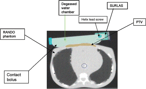
Plans were created for each MVCT data set with and without the SURLAS in place. When the SURLAS was placed on the phantom its long axis was either perpendicular or parallel to the longitudinal axis of the RANDO phantom (see and ). These positions correspond to the SURLAS scanning reflector moving transversely or superior-inferior with respect to the phantom.
Figure 4. SURLAS positioned with its long axis parallel to the longitudinal axis of the RANDO phantom simulating treatment to the superficial PTV.
SURLAS long axis parallel to the longitudinal axis of the phantom
The SURLAS electronics (transducers, connectors, stepper motor, cooling fan, etc.) were outside (superiorly and inferiorly of) the treatment field when its long axis was parallel (see ) to the longitudinal axis of the phantom. In this case, the electronics were not included in the MVCT planning data set because they would be outside the region where the heat and radiation is to be delivered. All plans were done using optimization parameters that are commonly used in our clinic for patient treatment. A jaw width of 2.5 cm and a normal dose grid resolution (2–4 mm pixel size) were used. The pitch and modulation factors used were 0.215 and 0.287, and 2.3 and 3.0, respectively. Beamlet (single active leaf from the MLC in a single projection) calculation time was approximately 45 min. Four plans were created for each PTV utilizing combinations of the above mentioned optimization parameters. The plan with the lowest beam-on time for each PTV was then re-calculated and re-optimized utilizing a fine dose grid resolution (1–2 mm pixel size) thus creating the fifth plan for each PTV with a beamlet calculation time of approximately 120 min. Actual optimization of all plans took approximately 30–45 min. The high density components of the SURLAS were either completely (the primary beams do not pass through the blocked structure) or directionally (the primary beams may pass through the blocked structure only if they pass first through a target structure) blocked by the use of constraints.
Figure 5. SURLAS positioned with its long axis perpendicular to the longitudinal axis of the RANDO phantom simulating treatment to the superficial PTV. Please note that a portion of the right sided SURLAS electronics is outside the field of view of the MVCT.

SURLAS long axis perpendicular to the longitudinal axis of the phantom
Since patients may also receive treatments with the reflectors scanning transversely across the phantom, planning was performed with the long axis of the SURLAS perpendicular to the longitudinal axis of the phantom and within the field of view of the MVCT (see ). Using this set-up, one plan for the superficial PTV was obtained using a normal dose grid resolution, a jaw width of 2.5 cm, a pitch of 0.287 and a modulation factor of 2.3. The SURLAS electronics were either completely or directionally blocked by the use of constraints.
Planning without the SURLAS on the phantom
One additional plan without the SURLAS and with the superficial PTV was created to determine if the presence of the SURLAS degrades the dose coverage of the PTV with respect to a radiation-only treatment course. The plan was performed using a normal dose grid resolution, a jaw width of 2.5 cm, and a pitch of 0.287 and a modulation factor of 2.3.
Radiation dose prescription
The prescription for all plans was specified to 95% of each PTV to receive 50 Gy in 25 equal fractions with a coefficient of variation or relative standard deviation (from now on referred to as coefficient of variation) of the dose within the PTV to be less than 3%. The coefficient of variation of the dose within the PTV is the interval within which the delivered mean dose to the PTV should be in order to ensure that the clinical end point is accurately achieved Citation[36]. Once all plans were finalized and accepted, PTV dosimetric parameters were recorded from the HT planning station (i.e., dose covering 95% of the PTV or PTV D95%, PTV average dose and PTV dose coefficient of variation defined as PTV dose Standard deviation divided by the PTV average dose). For the studied OAR, average doses were recorded, except for the spinal cord where the maximum dose was noted. No normalization of the PTV coverage dose was done for plan comparison purposes as the ratio of the planned coverage dose to the prescribed coverage dose ranged from 0.990 to 1.002 for all plans, which is well within the range of clinical variation.
Results
SURLAS long axis parallel to the longitudinal axis of the RANDO phantom
The results obtained by analysing each treatment plan are summarized in and , and and . Iso-dose evaluation (see ) shows acceptable sparing of all OAR. For the case of the deep PTV, the heart DVH shows a larger volume of the organ receiving a larger dose. This is due to the amount of dose overlap between the heart and the deep PTV. (also see corresponding DVH in ) shows the mean average dose in 25 fractions delivered to the high density components of the SURLAS. As these components were either directionally or completely blocked with the use of constraints, the doses shown are relatively low.
Figure 6. Typical isodose distribution (over 25 equal fractions) and dose-volume histogram for both deep (A) and superficial planning (B) target volume (PTV) with the SURLAS long axis parallel to the longitudinal axis of the RANDO phantom.
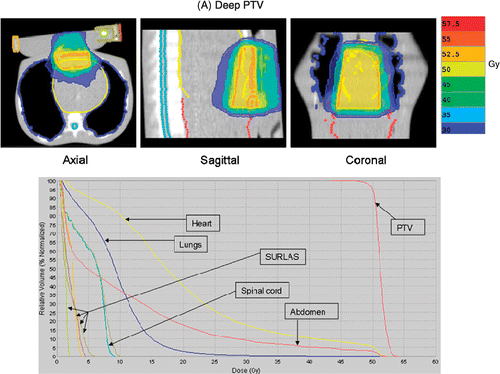
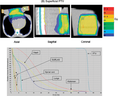
Table I. Average beam-on time (s) and coefficient of variation (%) of each planning target volume (PTV) for treatment plans where the long axis of the SURLAS is parallel to the longitudinal axis of the RANDO phantom.
Table II. Mean average dose (Gy) in 25 fractions to SURLAS high density components of each planning target volume (PTV) for treatment plans where the long axis of the SURLAS is parallel to the longitudinal axis of the RANDO phantom.
The superficial and deep PTV mean beam-on treatment times (see ) were 378 ± 48 and 364 ± 53 s, respectively. The highest beam-on time for the superficial (418 s) and deep (412 s) PTV plans was obtained with a pitch, modulation factor and dose grid resolution of 0.215, 3.0 and normal, and 0.287, 3.0 and normal, respectively. The lowest beam-on time for the superficial (316 s) and deep (297 s) PTV plans was obtained with a pitch, modulation factor and a dose grid resolution of 0.287, 2.3 and fine, and 0.287, 2.3 and normal, respectively. The superficial and deep PTV mean D95% was 49.8 ± 0.2 and 49.9 ± 0.1 Gy, respectively. Mean superficial and deep PTV average dose (see ) was 50.9 ± 0.3 and 51.2 ± 0.08 Gy, respectively. Mean superficial and deep PTV coefficient of variation (see ) was 1.2 ± 0.3 and 1.6 ± 0.1%, respectively.
Figure 7. Mean of average dose (Gy) to organs at risk (maximum dose (Gy) to spinal Cord) in 25 equal fractions for treatment plans with the long axis of the SURLAS parallel to the longitudinal axis of the RANDO phantom. PTV, planning target volume.
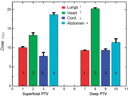
Superficial and deep PTV mean average dose (see ) in 25 fractions to the lungs, heart and abdomen were 10.1 ± 0.2, 13.3 ± 0.6 and 18.7 ± 0.5 Gy, and 9.3 ± 0.1, 20.2 ± 0.2 and 11.4 ± 1.0 Gy, respectively. Superficial and deep PTV mean maximum dose (see ) in 25 fractions to the spinal cord was 7.8 ± 1.0 and 9.4 ± 0.4 Gy, respectively. The highest average (maximum to the spinal cord) dose to the OAR for the deep PTV was seen with fine dose grid resolution. On the other hand, for the superficial PTV the highest average (maximum to the spinal cord) dose was seen with either a pitch and modulation factor of 0.215 and 3.0 (heart and abdomen) or 0.287 and 2.3 (lungs and spinal cord). Doses to all studied OAR are considered clinically acceptable.
SURLAS long axis perpendicular to the longitudinal axis of the RANDO phantom
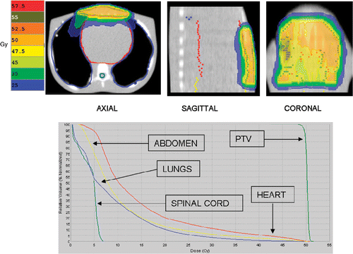
The results obtained by analysing each treatment plan are summarized in and . Iso-dose evaluation (see ) shows acceptable sparing of all OAR. For the case of complete blocking of the SURLAS's electrical components with the use of constraints, the median dose to all OAR are higher as compared to the plan where the electronics are directionally blocked. This is due to more doses being deposited via gantry angles that exclude the electrical components of the SURLAS. In addition, for this case, the use of complete blocking constraints results in an antero-posterior and postero-anterior type of dose distribution (see ). PTV D95%, coefficient of variation and beam-on time (see ) were 50.1 and 50.1 Gy, 2.8 and 1.6%, and 346 and 267 s, respectively, for the use of complete or directional blocking constraints of the SURLAS electronics.
Figure 8. Isodose distribution (over 25 equal fractions) and dose-volume histogram for the superficial planning target volume (PTV) with the SURLAS long axis perpendicular to the longitudinal axis of the RANDO phantom. The SURLAS electronics were either directionally (A) or completely (B) blocked by the use of constraints.
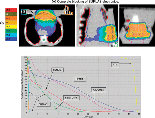
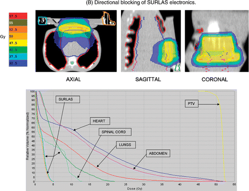
Table III. Beam-on time (s) and coefficient of variation (%) when blocking SURLAS electronics of the superficial planning target volume (PTV) for treatment plans where the long axis of the SURLAS is perpendicular to the longitudinal axis of the RANDO phantom.
RANDO phantom without the SURLAS
Treatment planning without the SURLAS showed clinically acceptable iso-dose line distributions and doses to all OAR (see ), as expected, with a beam-on treatment time of 333 s. The average OAR doses (maximum for the spinal cord) were 14.5, 7.0, 8.9 and 11.0 Gy for the heart, spinal cord, lungs and abdomen, respectively. The superficial PTV D95%, average dose and coefficient of variation were 49.6 Gy, 50.3 Gy and 0.8%, respectively.
Figure 9. Isodose distribution (over 25 equal fractions) and dose-volume histogram for the superficial planning target volume (PTV) without the SURLAS.
Comparison of treatment plans with and without the SURLAS
summarizes the dosimetric parameter comparison between treatment plans and SURLAS orientations. The PTV average dose and PTV D95% are similar for all plans. The coefficient of variation is the highest for the plan where complete blocking constraints for the SURLAS high density components are used. This is an expected finding as the use of complete blocking constraints does not permit primary beams passing through the blocked structure. The average dose to the heart was highest in the plan where complete blocking constraints were used for the SURLAS high density components as compared to the lowest average dose in the plan without the SURLAS. A similar finding is seen for the maximum dose to the spinal cord. The highest average dose to the lungs was seen with the plan where the long axis of the SURLAS was parallel to the longitudinal axis of the RANDO phantom. A similar finding was seen for the average dose to the abdomen. These findings are due to variation in constraint definition and its corresponding differential penalties. Nevertheless, all plans are clinically acceptable in terms of dose to critical structures and the dosimetric parameters of the PTV.
Table IV. Dosimetric parameter comparison between superficial PTV treatment plans.
Discussion
Simultaneous thermoradiotherapy has been shown to be clinically feasible and safe Citation[20]. Radiosensitizing effects of hyperthermia reach a maximum when both modalities are delivered simultaneously and decrease rapidly as the time between the modalities increases Citation[37–39]. Nevertheless, sequential thermoradiotherapy remains the most common way to deliver hyperthermia and radiation therapy; an approach that does not take full advantage of thermal (heat) radiosensitization. In 1995, the SURLAS was first described as a device for simultaneous electron/photon beam therapy (using conventional radiotherapy portals) and superficial hyperthermia. Since then, improved techniques of radiation treatment planning and delivery such as 3D conformal radiotherapy and IMRT have become widely available clinically. Therefore, we have evaluated the feasibility of delivering simultaneous thermoradiotherapy with advanced clinical radiation delivery technology such as helical tomotherapy. Moreover, IMRT affords a greater flexibility as compared to 3D conformal radiation therapy in dose sculpting and in conformal avoidance of the high density components of a hyperthermia applicator, thus avoiding the possible adverse effects of these components on the dose distribution. The IGRT capabilities of the HT unit allow correction of inter-fraction motion. This not only applies to the patient but to the SURLAS applicator as well. In other words, the MVCT capabilities of HT can be exploited to accurately reposition the patient and SURLAS for fractionated simultaneous thermoradiotherapy.
In principle, the time of concomitant thermoradiotherapy could be maximized using a HT unit. By selecting a tighter pitch and increasing the modulation factor for a given jaw width, the beam-on treatment time will increase as the couch speed moving through the bore of the ring gantry decreases. In addition, by carefully selecting the position of the SURLAS with respect to the longitudinal axis of the patient, a dosimetric advantage may be possible in terms of reducing dose to the OAR (see ). Studies in patients treated for cancer where the radiation beam passes through a steel or titanium hip prosthesis have shown that there is dose variation at the interface between tissue and the prosthesis which is not predicted by the radiation therapy planning station Citation[40–42]. Proper beam technique modifications are recommended to avoid the metallic prosthesis Citation[40], Citation[41]. This dose variation can be significant in terms of complications developed by the patient. As shown here, in the HT unit it is possible to use directional or complete blocking constraints to block an ROI. By judicious use of blocking constraints in the HT planning station it may be possible to reduce the over- or under-dosage area seen at the high density component to tissue proximal and distal interfaces, respectively.
The potential effects of the SURLAS on the photon beam from the HT unit are of interest. The reflector used in the SURLAS is made of near air-equivalent material contained in near water-equivalent material. Moros et al. Citation[22] have shown that these reflectors do not significantly perturb electron or photon beams regardless of the reflector's scanning speed. Note that our goal was not to determine the degree of degradation of a plan optimized with the SURLAS in comparison to a plan optimized without the SURLAS but to establish feasibility of clinically acceptable dose distributions of plans optimized with and without the SURLAS. We know of and expect certain ‘degradation’ of the quality of the radiation treatment plan when dose distributions for a patient with the SURLAS are compared for the same patient without the SURLAS, but this is not the goal of this study. Based on the clinical experience thus far with simultaneous thermoradiotherapy Citation[20], in most cases a greater number of fractions would be delivered without the SURLAS for which separate treatment plans are optimized. For the same reason skin or surface doses in plans with the SURLAS are not critical as a minority number of treatments will consist of simultaneous hyperthermia and radiation therapy. Furthermore, since the treatment targets extend to the surface of the phantom, the skin or surface is usually part of the target and skin sparing is actually avoided. Nevertheless, in this study, we assumed that hyperthermia was to be delivered simultaneously with every radiation fraction. This represents a worst case scenario producing the largest extent of potential dose distribution degradation from the use of the SURLAS.
Conclusion
Our results have shown the feasibility of concurrent treatment with the SURLAS and HT IMRT. It is known that for concomitant thermoradiotherapy thermal radiosensitization is maximized. It is of interest in the field of hyperthermia to find novel techniques that can implement and simplify the use of concomitant thermoradiotherapy without adversely affecting the quality of radiation treatments.
The dose distributions and dose statistics to the ROI obtained from the HT planning station are clinically acceptable regardless of the presence of the SURLAS. Practically, the presence of the SURLAS does not significantly degrade the quality of the radiation dose distributions planned in HT as demonstrated by various dosimetric parameters presented here. The advanced planning and delivery technology of HT can adequately compensate for the presence of the SURLAS and still render a highly conformal and clinically acceptable treatment plan. For specific cases the orientation of the SURLAS with respect to the longitudinal axis of the patient's body may provide some dosimetric advantage. Finally, the results presented here are encouraging and warrant further development for clinical implementation.
Related Research Data
References
- Dewhirst MW, Sneed PK. Those in gene therapy should pay closer attention to lessons from hyperthermia. Int J Radiat Oncol Biol Phys 2003; 57: 597–599, author reply 599–600
- van der Zee J. Heating the patient: A promising %. Ann Oncol 2002; 13: 1173–1184
- van der Zee J, et al. Comparison of radiotherapy alone with radiotherapy plus hyperthermia in locally advanced pelvic tumours: A prospective, randomised, multicentre trial. Dutch Deep Hyperthermia Group. Lancet 2000; 355: 1119–1125
- Sneed PK, et al. Survival benefit of hyperthermia in a prospective randomized trial of brachytherapy boost +/- hyperthermia for glioblastoma multiforme. Int J Radiat Oncol Biol Phys 1998; 40: 287–295
- Hand JW, et al. Analysis of thermal parameters obtained during phase III trials of hyperthermia as an adjunct to radiotherapy in the treatment of breast carcinoma. Int J Hyperthermia 1997; 13: 343–364
- Sherar M, et al. Relationship between thermal dose and outcome in thermoradiotherapy treatments for superficial recurrences of breast cancer: Data from a phase III trial. Int J Radiat Oncol Biol Phys 1997; 39: 371–380
- Vernon CC, et al. Radiotherapy with or without hyperthermia in the treatment of superficial localized breast cancer: Results from five randomized controlled trials. International Collaborative Hyperthermia Group. Int J Radiat Oncol Biol Phys 1996; 35: 731–744
- Overgaard J, et al. Randomised trial of hyperthermia as adjuvant to radiotherapy for recurrent or metastatic malignant melanoma. European Society for Hyperthermic Oncology. Lancet 1995; 345: 540–543
- Sugimachi K, et al. Chemotherapy combined with or without hyperthermia for patients with oesophageal carcinoma: A prospective randomized trial. Int J Hyperthermia 1994; 10: 485–493
- Valdagni R, Amichetti M. Report of long-term follow-up in a randomized trial comparing radiation therapy and radiation therapy plus hyperthermia to metastatic lymph nodes in stage IV head and neck patients. Int J Radiat Oncol Biol Phys 1994; 28: 163–169
- Datta NR, et al. Head and neck cancers: Results of thermoradiotherapy versus radiotherapy. Int J Hyperthermia 1990; 6: 479–486
- Dewhirst MW, et al. Basic principles of thermal dosimetry and thermal thresholds for tissue damage from hyperthermia. Int J Hyperthermia 2003; 19: 267–294
- Dewey WC. Arrhenius relationships from the molecule and cell to the clinic. Int J Hyperthermia 1994; 10: 457–483
- Myerson RJ, et al. Modeling heat-induced radiosensitization: Clinical implications. Int J Hyperthermia 2004; 20: 201–212
- Thrall DE, et al. Using units of CEM 43 degrees C T90, local hyperthermia thermal dose can be delivered as prescribed. Int J Hyperthermia 2000; 16: 415–428
- Vujaskovic Z, et al. Temperature-dependent changes in physiologic parameters of spontaneous canine soft tissue sarcomas after combined radiotherapy and hyperthermia treatment. Int J Radiat Oncol Biol Phys 2000; 46: 179–185
- Xu M, et al. Transfection of human tumour cells with Mre11 siRNA and the increase in radiation sensitivity and the reduction in heat-induced radiosensitization. Int J Hyperthermia 2004; 20: 157–162
- Kampinga HH, Dynlacht JR, Dikomey E. Mechanism of radiosensitization by hyperthermia (> or = 43°C) as derived from studies with DNA repair defective mutant cell lines. Int J Hyperthermia 2004; 20: 131–139
- Armour EP, Raaphorst GP. Long duration mild temperature hyperthermia and brachytherapy. Int J Hyperthermia 2004; 20: 175–189
- Myerson RJ, Straube WL, Moros EG, Emami BN, Lee HK, Perez CA, Taylor ME. Simultaneous superficial hyperthermia and external radiotherapy: Report of thermal dosimetry and tolerance to treatment. Int J Hyperthermia 1999; 15: 251–266
- Novák P, et al. SURLAS: A new clinical grade ultrasound system for sequential or concomitant thermoradiotherapy of superficial tumors: Applicator description. Med Phys 2005; 32: 230–240
- Moros EG, et al. Simultaneous delivery of electron beam therapy and ultrasound hyperthermia using scanning reflectors: A feasibility study. Int J Radiat Oncol Biol Phys 1995; 31: 893–904
- Moros EG, Fan X, Straube WL. An investigation of penetration depth control using parallel opposed ultrasound arrays and a scanning reflector. J Acoust Soc Am 1997; 101: 1734–1741
- Moros EG, Fan X, Straube WL. Experimental assessment of power and temperature penetration depth control with a dual frequency ultrasonic system. Med Phys 1999; 26: 810–817
- Moros EG, et al. Numerical and in vitro evaluation of temperature fluctuations during reflected-scanned planar ultrasound hyperthermia. Int J Hyperthermia 1998; 14: 367–382
- Moros EG, Straube WL, Myerson RJ. Potential for power deposition conformability using reflected-scanned planar ultrasound. Int J Hyperthermia 1996; 12: 723–736
- Novák P, Moros E, Straube W, Myerson R. Treatment delivery software for a new clinical grade ultrasound system for thermoradiotherapy. Med Phys 2005; 32: 3246–3257
- Mackie TR, et al. Tomotherapy. Semin Radiat Oncol 1999; 9: 108–117
- Mackie TR, et al. Tomotherapy: A new concept for the delivery of dynamic conformal radiotherapy. Med Phys 1993; 20: 1709–1719
- Yang JN, et al. An investigation of tomotherapy beam delivery. Med Phys 1997; 24: 425–436
- Kapatoes JM, et al. Delivery verification in sequential and helical tomotherapy. Phys Med Biol 1999; 44: 1815–1841
- Kapatoes JM, et al. A feasible method for clinical delivery verification and dose reconstruction in tomotherapy. Med Phys 2001; 28: 528–542
- Penagaricano JA, Papanikolaou N. Intensity-modulated radiotherapy for carcinoma of the head and neck. Curr Oncol Rep 2003; 5: 131–139
- Grigorov G, et al. Optimization of helical tomotherapy treatment plans for prostate cancer. Phys Med Biol 2003; 48: 1933–1943
- Shepard DM, et al. Iterative approaches to dose optimization in tomotherapy. Phys Med Biol 2000; 45: 69–90
- Aaltonen P, et al. Specification of dose delivery in radiation therapy. Recommendation by the Nordic Association of Clinical Physics (NACP). Acta Oncol 1997; 36(Suppl.10)1–32
- Overgaard J. Simultaneous and sequential hyperthermia and radiation treatment of an experimental tumor and its surrounding normal tissue in vivo. Int J Radiat Oncol Biol Phys 1980; 6: 1507–1517
- Overgaard J. The current and potential role of hyperthermia in radiotherapy. Int J Radiat Oncol Biol Phys 1989; 16: 535–549
- Horsman MR, Overgaard J. Hyperthermia: A potent enhancer of radiotherapy. Clin Oncol 2007; 19: 418–426
- Burleson WD, et al. In vivo isocenter dose in two hip prosthesis patients. Int J Radiat Oncol Biol Phys 1991; 20: 1347–1352
- Ding GX, Yu CW. A study on beams passing through hip prosthesis for pelvic radiation treatment. Int J Radiat Oncol Biol Phys 2001; 51: 1167–1175
- Sibata CH, et al. Influence of hip prostheses on high energy photon dose distributions. Int J Radiat Oncol Biol Phys 1990; 18: 455–461