Abstract
Purpose: A reentrant-cavity-based applicator can produce a concentrated electric field between reentrant electrodes for localized heating. However, this field is inadequate for treating early small tumors localized in the head and neck. In order to safely heat such well-localized lesions, the electric field distribution should be more localized.
Materials and methods: In order to achieve localized heating, four parameters of the reentrant cavity (applicator height, outer diameter, reentrant diameter, and reentrant gap size), which influence the distribution of the electric field produced in the reentrant gap, are optimized using the Taguchi method. The variation in the heating characteristics affected by the size of the heating object is estimated using the signal-to-noise ratio (SNR) index. In this study, the electromagnetic field distributions in a cylindrical phantom and an oblate sphere phantom are analyzed by the three-dimensional finite element method, and the full width at half height (FWHH) of the specific absorption rate (SAR) distribution in the reentrant gap is evaluated.
Results: It is shown that the optimized applicator yields both the maximum SNR and minimum mean FWHH, and the sizes of the heating region in the phantom expressed using the averaged FWHH values of the SAR distribution are 60 and 80 mm along the radial and long-axis directions of the applicator, respectively.
Conclusions: A heating region can be robustly and optimally localized by using the Taguchi method and considering the variation in the size of the heating object.
Introduction
Hyperthermia is an effective therapeutic technique that is used in radiotherapy or carcinostatic therapies. However, the regression mechanism and the therapeutic effect on cancerous tissues are not always clear when only heating procedure is carried out independently. This is because it is difficult to heat a local region in a living body to the required temperature in vivo and to perform noninvasive and precise temperature measurements in a living body.
Currently, different noninvasive methods have been proposed for hyperthermia, including thermal ablation. Some of these methods involve the application of heat on an object using dipole antennas with different amplitudes and phases Citation[1–4] or by high-temperature thermal ablation using focused ultrasound Citation[5–8]. However, when the method that uses pairs of dipole antennas is applied, it is difficult to heat only a deep local region, and a water bolus is usually required to avoid heating the body surface Citation[4]. On the other hand, when the method using focused ultrasound is applied, it is observed that the properties of ultrasonic waves limit the application site.
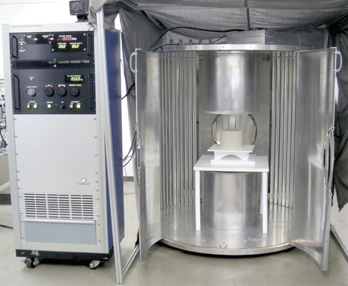
In order to noninvasively heat a deep region in a living body, we consider the electric field distribution in a reentrant cavity, which is widely used in microwave devices such as cavity-based transducers Citation[9] and electron spin resonance (ESR) spectrometers Citation[10]. A reentrant cavity is a resonator in which the inner cylinders (known as reentrant electrodes) are attached to the upper and lower sides of a cylindrical cavity resonator. Since an intense electric field is produced in the gap between the reentrant electrodes, a standing wave electric field distribution is formed in the living body when it is placed in the gap; thus, a deep region in the body can be heated effectively. Based on this concept, we have developed a general applicator, which is shown in , and have demonstrated its feasibility by numerical and animal experiments Citation[11–14]. However, since the region where the electric field is concentrated is relatively large, it is difficult to achieve further localization to safely heat the early small tumors, for example, tumors of the head and neck.
In this study, we aim to develop a reentrant-type applicator that can heat small localized regions. It is expected that the electric field distribution can be localized by the miniaturization of the applicator; however, a simple miniaturization would result in an increase in the resonant frequency and degradation of the heating characteristics. Therefore, it is necessary to select four suitable parameters (namely, applicator height, outer diameter, reentrant diameter, and reentrant gap size) that describe the reentrant-type applicator and optimize them in order to achieve the required localized heating characteristics. In addition, since the localized heating characteristics are also influenced by the size of the object inserted in the reentrant gap, the optimization of the heating characteristics becomes difficult and complicated. Under these conditions, the Taguchi method Citation[15], which is a technique used for optimizing several variables with high reliability, is very useful Citation[16]. One of the features of this method is the classification of the variables that affect the response of an objective function into controllable input variables and the variables that cannot be controlled directly, in order to optimize the objective function. Therefore, robust optimization of the localized heating characteristics, which is not influenced by the size of the heating object (cannot be chosen arbitrarily), is achieved by using this method.
In this study, a numerical analysis in combination with the Taguchi method and three-dimensional finite element method (3D FEM) reveals that the localized heating characteristics of the reentrant-type applicator are optimized by evaluating the full width at half height (FWHH) of the specific absorption rate (SAR) distribution produced in the reentrant gap.
Principle
Concentration of electric field using reentrant cavity
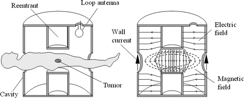
The principle of the reentrant-cavity-based applicator is explained by the mimetic diagram shown in . In this applicator, the reentrant electrodes are attached to the upper and lower sides of the cylindrical cavity resonator. The RF power required for heating is supplied by the loop antenna attached to the upper surface of the cavity resonator. In the following paragraphs, the characteristics of the electromagnetic field distribution produced in the reentrant cavity are explained and compared with those of the conventional RF capacitive heating system, which is widely used in clinics.
Figure 2. Cross section of applicator and electromagnetic field distribution of the lowest (TM010) mode in reentrant cavity.
In the RF capacitive heating system, since the wavelength of an applied electromagnetic wave in the living body is sufficiently large in comparison to the distance between the electrodes, the electromagnetic field distribution can be approximately described by Laplace's equation. On the other hand, the electromagnetic field distribution in the reentrant cavity is described by the Helmholtz equation, which is expressed as follows:(1) where E is the electric field (V/m); H, the magnetic field (A/m); ω, the excitation angular frequency (rad/s); ϵ, the permittivity (F/m); μ, the permeability (H/m); σ, the conductivity (S/m); and ϵ*, the complex permitivity.
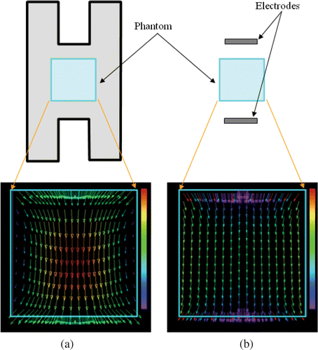
Under resonant conditions, the electromagnetic field modes in the reentrant cavity combine into a single mode for which the electric field is concentrated in the gap between the electrodes, as shown in . The basic electromagnetic field distribution in this mode is similar to that in the TM010 mode of the cylindrical cavity resonator based on the RF current flowing along the walls of the resonator; this is the most significant difference between the reentrant cavity and RF capacitive heating systems Citation[17]. Accordingly, the strength of the electric field in the gap will be the highest near the center, and it will decrease rapidly in the radial direction as compared to that in a capacitive heating system, as shown in . Therefore, if a living body is introduced in the reentrant gap, localized heating of a deep region corresponding to the center of the gap can be carried out. Furthermore, in the RF capacitive heating system, since regions with a high field strength are formed at the ends of the electrodes due to the edge effect, enhanced heating may be achieved in these regions. On the other hand, although such regions are formed in the reentrant cavity heating system, it is apparently difficult to achieve enhanced heating since the electric fields at the ends of the electrodes are sufficiently weaker than those in the central region of the electrodes. The above mentioned characteristics of the electric field distribution enable non-contact heating of only the tumor tissue in the deep localized region of a living body without the requirement of a water bolus.
Figure 3. Outline of electric field distributions in (a) reentrant cavity and (b) RF capacitive heating system.
Thus far, we have developed an applicator for heating tumors in the abdominal region Citation[11–13]. However, since the conventional equipment cannot sufficiently localize the electric field, it is necessary to develop a method that can facilitate field localization so that only the tumors are heated, such as tumors in the head and neck. The miniaturization of the reentrant applicator can be considered for the localization of the electric field distribution. However, if the reentrant applicator is simply miniaturized for the localization of the electric field, the characteristics for heating deep regions may degrade due to an increase in the resonant frequency f0, which is approximately expressed in Equation 2 Citation[17], thereby posing a serious problem:(2) where c0 is the velocity of light (m/s), and the other symbols denote the parameters of the applicator indicated in . Therefore, it is necessary to optimize the heated characteristics by miniaturization considering the degradation of the characteristics accompanying the increase in the resonant frequency. In addition, it is necessary to consider that the localized heating characteristics are influenced by the size of the heating object inserted in the reentrant gap. Therefore, we need to use the Taguchi method.
Optimization of local heating characteristics by Taguchi method
The Taguchi method has been proposed by G. Taguchi in order to improve engineering productivity with high reliability Citation[15]. One of the most important features of this method is that it introduces noise factors into the general design of experiment (DOE). For example, it is assumed that there are some uncontrollable environmental factors (noise factors) in addition to the parameters that control a certain target system. Conventionally, the effects of these parameters have been considered equally and the optimization of the system has been attempted. Consequently, although the control of the target system is satisfactorily possible under certain environmental conditions, a change in the environmental conditions may have a significant effect on the performance of the target system. On the other hand, Taguchi has pointed out the usefulness of considering all parameters as an arrangement of inner and outer array factors over which we have design control and control only in the laboratory, respectively. An example of a matrix created by the Taguchi method (L8 orthogonal matrix) is shown in . In this example, levels 1 and 2 occur 4 times for each control factor (C1–C4) in the inner array. Hence, this array is an orthogonal and fractional factorial matrix that ensures a balanced comparison of the levels of any control factor. According to the property of this orthogonal array, if the responses of the target system (R1,1–R8,1 and R1,2–R8,2) are determined by running the complete set of noise factor settings (2 noise conditions mentioned in ) for each combination of control factor settings, the contribution of each factor to the response of the target system can be evaluated independently of all the other factors.
Table I. Taguchi's orthogonal L8 matrix (Example).
Another feature of the Taguchi method is that the signal-to-noise ratio (SNR) of responses is taken into consideration in addition to the optimization of the target performance. The SNR is defined by Equation 3 in the smaller-the-better case:(3) where Rk,n indicates the collected response values of the target system according to run number k for each combination of control factors and the noise factor n (e.g., R1,1–R8,1 and R1,2–R8,2 mentioned in ), and N denotes the total number of noise factors required for each run. In the smaller-the-better case, the optimized robust target performance, which is not influenced by the uncontrollable noise parameters, is achieved when the SNR is the maximum, that is, when the system response is the minimum.
Methods
In order to optimize the localized heating characteristics, the applicator is optimally miniaturized by the following procedures, which are based on the Taguchi method and 3D FEM.
Selection of control and noise factors
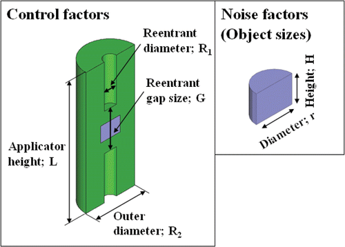
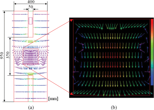
The parameters that describe the size of a reentrant-type applicator are the applicator height L, outer diameter R1, reentrant diameter R2, and reentrant gap size G, as shown in . These parameters are known as control parameters, and they influence the distribution of the electric field produced in the reentrant gap. On the other hand, the localized heating characteristics are also influenced by the size of the heating object inserted in the gap. In this study, the heated objects are made into cylindrical phantoms; they have different diameters and heights, which are known as their noise factors.
Setting of levels for each control and noise factor
From our previous study using the reentrant-type applicator, we have found that the heating characteristics degrade remarkably when the resonant frequency increases considerably due to the miniaturization of the cavity resonator. Therefore, the parameter level that is suitable for a resonant frequency of less than 200 MHz is selected, as indicated in . Considering that a human head will be introduced in the reentrant gap, the gap space should be approximately 300–400 mm. The phantom size, i.e., noise factor, is 115–160 mm in diameter and 110–160 mm in height. However, in order to reduce the experimental trial frequency, the noise factors are combined Citation[15] and degenerated in 2 states – a large phantom (r = 160 mm, H = 160 mm) and a small phantom (r = 115 mm, H = 110 mm), as indicated in . The center of the phantom coincides with the center of the reentrant gap, and this point is considered to be the origin for the evaluation of the heating characteristics, as mentioned later.
Table II. Levels of control factors and degenerated noise factors.
Arrangement of each level in Taguchi's orthogonal array
The level for each factor mentioned above can be assigned to a combination of levels 2 and 3 of Taguchi's orthogonal matrix array (L18 orthogonal array). This matrix array can have one factor with 2 levels and a maximum of seven factors with 3 levels each. In this study, the applicator height is set such that it is equal to the factor with 2 levels and the other parameters are set such that they are equal to 3 factors with 3 levels, comprising the inner array. At the same time, the phantom size is set as a noise factor, and it comprises the outer array, as indicated in . The SAR distribution described as the response data corresponding to R1,1–R18,1 and R1,2–R18,2 is calculated by the following method: for each run of the noise factors in the outer array, the response data corresponding to R1,1–R18,1 and R1,2–R18,2 are aligned in a row adjacent to the factors’ settings for that run of the control factors in the inner array. Finally, 36 runs corresponding to the multiplication of control factors (18) and noise factors (2) are performed.
Table III. Taguchi's orthogonal matrix array (L18 orthogonal array).
Calculation of electromagnetic field for each condition using FEM
The electromagnetic field distribution in the reentrant cavity generally satisfies Equation 1. In this study, the electromagnetic field (both and
fields) in the closed cavity is calculated using 3D FEM by running the complete set of settings of noise factors for each combination of the settings of control factors. The FEM analysis is performed by setting the number of nodes and elements to approximately 15000 and 1000, respectively. The cavity surface wall is considered to be a perfect electric conductor (PEC) boundary, and it is treated as a boundary in which the tangential component of the electric field vector E vanishes. Although RF energy is supplied to the applicator, as shown in , on the basis of the magnetic field generated by the loop antenna, the TM010 mode is excited in this calculation by the application of a potential difference to an FEM element side between a reentrant electrode and the inner wall of the cavity. The electric parameters used in this analysis are listed in . The resonant condition of the cavity resonator is determined from the electric field strength (Ez) at the center of the reentrant gap by considering the excited electromagnetic mode.
Table IV. Electric parameters used in 3D-FEM simulation.
Evaluation of SAR distribution in heated object
In order to evaluate the heating characteristics, the SAR distribution inside the phantom, which represents the size of the heat source, is calculated, and the FWHH values of the SAR distributions along the radial (r) and long-axis (Z) directions are estimated (). Here, the SAR value denotes the energy absorbed by a substance (tissue) of unit mass in unit time, and it is given by the following equation:(4) where ρ is the density of the target material (kg/m3); σ, the conductivity of the target material (S/m); and |E|, the magnitude of the electric field (V/m).
Figure 5. Definition of SAR distribution along the radical and long-axis directions in the phantom (a) used for the evaluation of heating characteristics.
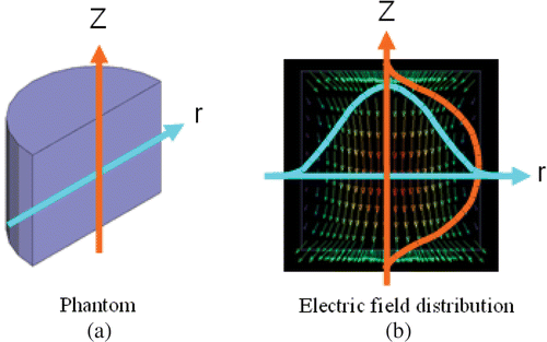
Finally, the simulated and calculated FWHH values are arranged as the response data Rk,n for each condition in the L18 orthogonal array.
Determination of robust condition from SNR and mean value of response
In order to find the optimal combination of control factors that achieves the best local heating characteristics along with robustness against noise factors, the averages of the SNR at each level for each factor are first calculated. They indicate the most sensitive and robust level for each factor against the system response based on the variation in the FWHH of SAR distribution. Then, the mean values of the response at each level for each factor are also calculated. Based on the above-mentioned two-step optimization, it is shown that the combination with a small value of the mean FWHH yields the best localized heating characteristics, and the combination with a high SNR of the FWHH reveals that there is a slight variation in the heating region with respect to the size of the heating object (phantom).
Evaluation of heating characteristics
After the optimization of the reentrant-type applicator, the heating pattern is verified by using Equation 5, which gives the heat transport equation for a living body Citation[18]. In our phantom study, we have ignored the terms of convection heat and bioheat (namely, the heat produced by blood flow and metabolism) and considered the electric field distribution determined by the electromagnetic field analysis as the heat source Wh.(5) where, ρ is the density of the medium (kg/m3); c, the specific heat of the medium [kJ/(kg · K)]; T, the temperature (K); t, the time (s); and κ, the heat conductivity of the tissue [W/(m · K)]. The term Wh denotes the absorbed power density (W/m3), and is given as follows:
(6)
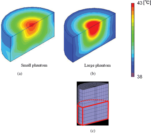
The increase in the temperature of the phantom according to Equation 5 is analyzed by 3D FEM using the thermal parameters of the phantom listed in Citation[19]. In this temperature analysis, the input electric field strength is adjusted such that the SAR value is 20 W/kg at the center of the phantom, and heating is carried out for 20 min.
Table V. Thermal parameters used in calculation of temperature distribution.
Results
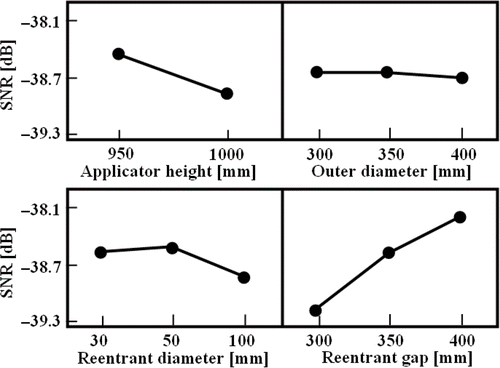
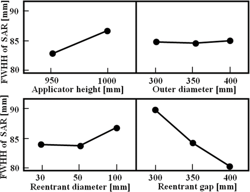
According to the generated combination of the elements of the L18 orthogonal array, the FWHH values of the SAR distributions calculated and evaluated by 3D FEM are obtained. In order to determine the factors that affect the FWHH value of the SAR distribution, the above mentioned two-step optimization, which involves reducing the variation in the FWHH value and adjusting the mean value of the FWHH, is carried out. shows the SNR of the FWHH for each level of the control factors. The combination that has the largest effect on the SNR value (minimum variation), i.e., the combination in which the values of the applicator height, outer diameter, reentrant diameter, and reentrant gap size are 950, 350, 50 and 400 mm, respectively, with a resonant frequency of approximately 195 MHz, should be selected as a candidate for the optimal factor. Then, once the combination of the control factors that reduces variations is determined, it is necessary to confirm whether it minimizes the FWHH value of the SAR distribution from , indicating the mean value of the response at each level for each factor. In this case, it is shown that the above combination of control factors yields both the maximum SNR and minimum mean FWHH.
The electric field distribution inside the cavity resonator on the central plane is shown in , and the normalized SAR distribution expressed in terms of the coordinates of the center of the phantom coinciding with the center of the resonant cavity is shown in . As a result, the sizes of the heating region expressed in terms of the averaged FWHH value of the SAR distribution are 60 and 80 mm along the r- and Z-directions, respectively.
shows the result of the evaluation of the heating characteristics of the optimized applicator and reveals the temperature distribution of the central planes in the phantom, which correspond to an area equal to one-fourth of the area of lower part of the phantom (), 20 min after the start of the heating process when the SAR value at the center of the phantom is adjusted to 20 W/kg. It is observed that the temperature at the center of the phantom increases. The heated region was 78 mm in diameter, which suggests that deep localized heating is possible.
Discussion
In order to achieve localized heating, we have previously developed an applicator by trial and error. Although it is confirmed that this applicator can heat only the central region of the phantom and its result is in good agreement with the simulation result, it is difficult to predict whether it is possible to carry out regional heating with this system. On the other hand, it is demonstrated that the influence of the control factors (applicator height, outer diameter, reentrant diameter, and reentrant gap size) on the size of the heating region can be quantitatively evaluated by using the Taguchi method. The advantage of the Taguchi method is that we can obtain the optimal solution without the influence of noise factors and significantly reduce the frequency of trial experiments or analysis. In this investigation, when the radius and length of the phantom are used as noise factors by considering the size of the heating object in terms of four control factors, the analysis requires 216 (combination of control factors (21 × 33) multiplied by combinations of noise factors (22)), different types of finite element methods are required, and a large analysis time. In contrast, the use of the orthogonal array matrix based on the Taguchi method allows us to find the optimal solution by repeating the analysis 36 times.
As mentioned above, it is possible to achieve an optimized heating region when the averaged FWHH values of the SAR distribution are 60 and 80 mm along the r-and Z-directions, respectively, which correspond to improvements of approximately 28% and 12% in the r-and Z-direction as compared to the results obtained with our previous applicator. As well as, it is confirmed that such optimization improves the heating characteristics inside the oblate sphere phantom (major axis = 160 mm, minor axis = 120 mm) 15% and 14% in the r- and Z-direction, respectively ().
Figure 11. Electric file distributions inside an oblate sphere phantom in (a) optimized applicator and (b) our previous applicator, and (c) those normalized SAR distributions.
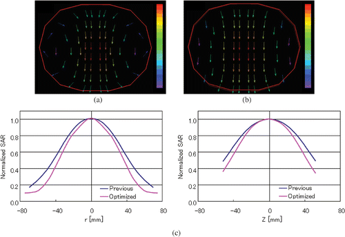
However, unless the broadening (FWHH) of the SAR distribution along both the r- and Z-directions is considered, robust localized heating characteristics cannot be obtained depending on the size of the phantom. For example, shows the SAR distributions obtained by using the Taguchi method and evaluating only the FWHH value along the r-direction. Although the SAR distributions are localized in the r-direction, it is shown that the electric field strength (SAR) at the surface of the small phantom increases; therefore, the heating characteristics would degrade depending on the size of the phantom in the Z-direction. It is considered that the optimal robust heating characteristics are obtained only by taking all the uncontrollable variables into consideration as noise factors in the Taguchi method.
Figure 12. Normalized SAR distributions optimized using FWHM for both r- and Z-directions and that only for the r-direction.

On the other hand, it is found that the heating characteristics along the Z-direction are not focused as compared to those in the r-direction not only when the abovementioned FWHH value along the r-direction is considered as an evaluation function but also when the FWHH values along both the r- and Z-directions are considered. Therefore, in addition to the optimization of the applicator size, another approach becomes indispensable in order to achieve further focusing of the heating region. This approach involves the formation of a cylindrical electric field distribution that converges along the r-direction without taking into consideration the convergence effect along the Z-direction. In this approach it is expected that the heating applicator is rotated around the r-axis. Since such an electric field distribution resembling a pencil beam is applied from many directions as a result of the rotation of the applicator, a focal point of heating can be formed at the center of the rotating r-axis of the applicator such that the electric fields intersect each other. We are currently examining whether such a focal point can be obtained.
In addition, if the heat source localized at the center of the applicator is controlled temporally, it can be assumed that further localization is possible. For this purpose, real-time noninvasive temperature measurement is required. We have also examined the possibility of noninvasive temperature measurement by using the property of standing waves in the reentrant-type applicator Citation[20], Citation[21], and we expect that small localized tumors can be heated effectively by using this method.
Conclusions
A heating region can be robustly and optimally localized using the Taguchi method by taking into consideration the variation in the size of the heating objects. The broadening of the electric field distribution (SAR) as the heat source is localized to approximately 60–80 mm in diameter. If the average size of the heating region is taken into consideration, it may be difficult to achieve more localization by using this system. In particular, it is difficult to focus the electric field along the Z-axis. However, since it is relatively easy to focus the electric field along the r-direction, the focal point of heating can be formed at the center of the applicator if the cylindrical electric field along the Z-direction is focused by rotating the applicator about the Z-axis. In addition, it is possible to control the temperature distribution by simultaneously using noninvasive thermometry based on the characteristics of the cavity applicator. By combining such techniques, completely noninvasive cancer therapy systems can be developed that can safely heat early small tumors localized in the head and neck.
Acknowledgement
This study was supported by the Industrial Technology Research Grant Programme in 2006 of the New Energy and Industrial Technology Development Organization (NEDO) of Japan.
Declaration of interest: The authors report no conflicts of interest. The authors alone are responsible for the content and writing of the paper.
References
- Seebass M, Reck R, Gellermann J, Nadobny J, Wust P. Electromagnetic phased arrays for regional hyperthermia: Optimal frequency and antenna arrangement. Int J Hyperthermia 2001; 17: 321–336
- Nadobny J, Fahling H, Hagmann MJ, Turner PF, Wlodarczyk W, Gellermann JM, Wust P. Experimental and numerical investigation of feed-point parameters in a 3-D hyperthermia applicator using different FDTD models of feed networks. IEEE Trans Biomed Eng 2002; 49: 1348–1359
- Gellermann J, Wlodarczyk W, Hildebrandt B, Ganter H, Nicolau A, Rau B, Tilly W, Fahling H, Nadobny J, Felix R, et al. Noninvasive magnetic resonance thermography of recurrent rectal carcinoma in a 1.5 Tesla hybrid system. Cancer Res 2005; 65: 5872–5880
- Nadobny J, Wlodarczyk W, Westhoff L, Gellermann J, Felix R, Wust P. A clinical water-coated antenna applicator for MR-controlled deep-body hyperthermia: A comparison of calculated and measured 3-D temperature data sets. IEEE Trans Biomed Eng 2005; 52: 505–519
- Lynn JG, Zwemer RL, Chick AJ, Miller AE. A new method for the generation and use of focused ultrasound in experimental biology. J Gen Physiol 1942; 26: 179–193
- Hynynen K, Clement GT, McDannold N, Vykhodtseva N, King R, White PJ, Vitek S, Jolesz J. A 500-element ultrasound phased array system for noninvasive focal surgery of the brain: A preliminary rabbit study with ex vivo human skulls. Magn Reson Med 2004; 52: 100–107
- McDannold N, Tempany CM, Fennessy FM, So MM, Rybicki FJ, Stewart EA, Jolesz FA, Hynynen K. Uterine leiomyomas: MR imaging-based thermometry and thermal dosimetry during focused ultrasound thermal ablation. Radiology 2006; 240: 263–272
- Furusawa H, Namba K, Thomasen S, Akiyama F, Bendet A, Tanaka C, Yasuda Y, Nakahara H. Magnetic resonance-guided focused ultrasound surgery of breast cancer: Reliability and effectiveness. J Am Coll Surg 2006; 203: 54–63
- Fujisawa K. General treatment of klystron resonant cavities. IRE Trans Microwave Theory and Tech 1958; 6: 344–358
- Giordano M, Momo F, Sotgiu A. On the design of a re-entrant square cavity as resonator for low-frequency ESR spectroscopy. J Phys E: Sci Instrum 1983; 16: 774–779
- Matsuda J, Kato K, Saitoh Y. The application of a re-entrant type resonant cavity applicator to deep and concentrated hyperthermia. Japan J Hyperthermia Oncol 1988; 4: 111–118
- Kato K, Wadamori N, Matsuda J, Uzuka T, Takahashi H, Tanaka R. Improvement of the resonant cavity applicator for brain tumor hyperthermia. Proc IEEE EMBS 2003; 25: 3271–3274
- Wadamori N, Matsuda J, Takahashi H, Grinev I, Uzuka T, Tanaka R. Heating properties of a re-entrant cavity-type applicator for deep regional hyperthermia treatments. Proc 9th Int Congress Hyperthermic Oncol. 2004, 169
- Ishihara Y, Gotanda Y, Wadamori N, Matsuda J. Hyperthermia applicator based on reentrant cavity for localized head and neck tumors. Rev Sci Inst 2007; 72: 243011–243018
- Taguchi G, Chowdhury S, Wu Y, Taguchi S, Yano H. Taguchi's Quality Engineering Handbook. John Wiley & Sons, Inc., Hoboken, NJ 2004
- Ishihara Y, Minegishi Y, Wadamori N. A heating applicator based on a reentrant cavity with optimized local heating characteristics. STM/WCIO Joint Annual Meeting. Washington, DC 2007; 232–233
- Slater JC. Microwave electronics. Dover, New York 1969
- Pennes H. Analysis of tissue and arterial blood temperatures in the resting human forearm. J Appl Physiol 1948; 1: 93–122
- Leonard JB, Foster KR, Athey TW. Thermal properties of tissue equivalent phantom materials. IEEE Trans Biomed Eng 1984; 31: 533–536
- Ishihara Y, Endo Y, Wadamori N, Ohwada H. A noninvasive temperature measurement regarding the heating applicator based on a reentrant cavity. STM/WCIO Joint Annual Meeting. Washington, DC 2007; 230–231
- Ishihara Y, Endo Y, Ohwada H, Wadamori N. Noninvasive thermometry in a reentrant resonant cavity applicator. 29th IEEE EMBS Annual International Conference, Lyon, 2007, 1487–1490
