Abstract
Purpose: In Rotterdam, fifteen years of clinical experience with deep hyperthermia has sublimated in empirical treatment guidelines. In this paper, a hyperthermia treatment planning system (HTPS) is employed to investigate the effect of these guidelines on global power distribution, their effectiveness and the rationale behind each guideline.
Materials and methods: Four guidelines were investigated. The first two prescribe steering actions for balancing intraluminal temperatures and alleviating complaints of deep-seated pain or pressure. The third guideline handles superficial complaints of pain or heat sensation. The last guideline states that frequency should be increased from 77 MHz upwards in case of multiple, opposite, painful regions uncontrollable by the previous steering actions.
For all steering actions it is assumed that input power is increased until complaints occur. Sigma Hyperplan was used to calculate specific absorption rate (SAR) distributions for five patient models with locally advanced cervical cancer. Absorbed power ratios of different regions of interest were evaluated to illustrate steering efficacy and complaint reduction.
Results and conclusions: Phase steering is effective in shifting the central power distribution to the periphery, and is an appropriate method to balance temperatures or to handle deep-seated complaints. Reduction of amplitude is the proper action to alleviate superficial complaints of heat or pressure. Compression of the SAR distribution, mainly in the lateral direction, is predicted with increasing frequency. Hence, for complaints in the lower back or on the sides, a frequency increase should be considered.
We conclude that the results of the HTPS are in close agreement with the empirical steering guidelines.
Introduction
In the Netherlands, adjuvant loco-regional deep hyperthermia (DHT) in combination with radiotherapy is standard treatment for locally advanced cervical cancer. In Rotterdam, over 15 years of experience in the application of DHT treatments with the BSD 2000-3D system has provided vast experience and benefited many hundreds of patients Citation[1–3].
To gain more insight in the heating process, detailed knowledge of the absorbed power and temperature distribution by RF radiation is required. In situ monitoring, however, is complicated. Conventional temperature or E-field probes can be used only at a limited amount of sites. Recently, much effort is invested in non-invasive, spatially resolved, temperature measurement techniques Citation[4],Citation[5].
Alternatively, the introduction of planning systems (HTPS) in hyperthermia has improved both the development of new applicators as well as the understanding of patient-specific factors on the distribution of power and temperature. Due to the considerable effort required to build patient models, systematic use of treatment planning systems to prescribe or support an optimized treatment strategy has not yet been realized.
Parallel to the development of HTPSs, the experience obtained in Rotterdam over the last two decades has sublimated into empirical steering guidelines resulting in an effective application of DHT Citation[1–3]. These steering guidelines not only provide the initial antenna settings to start a treatment, but also give a power on/off policy and indicate how to adjust settings in case of patient complaints concerning hot spots or too high or unevenly distributed measured temperatures.
In this paper we compare these two approaches. For the first time, a HTPS is used to evaluate a selection of rules from the Rotterdam empirical steering guidelines (RESG). That is, we investigate the effect of some of these guidelines on the global power distribution, and check their effectiveness under the conditions imposed. Further, we check whether the rationale behind each guideline is correct.
Absolute and detailed verification of planning systems for patient-specific modeling is cumbersome and subject to ongoing research Citation[6],Citation[7]. Therefore, in this study we are only looking for general similarities and differences between the guidelines and the planning results. We will not address power absorption in specific hot spots.
Four guidelines are evaluated. Firstly, a guideline is introduced prescribing how to correct for an unbalanced temperature distribution, secondly, how to treat deep-seated pain/pressure, thirdly, how to alleviate superficial heat complaints, and finally, the if-everything-fails frequency steering guideline.
A detailed description of these guidelines can be found in the following section.
Materials and methods
In this section we first describe the selected steering guidelines that will be evaluated in this paper. Then, the treatment planning system and patient model construction are outlined, and finally, the methods for comparison and analysis of the calculations are discussed.
Steering guidelines
Specific absorption rate (SAR) steering is the term to address all changes in antenna settings that affect the distribution of dissipated power. This can be done by introducing a phase-shift between the various antennas of an applicator, by varying the relative amplitudes of the antennas or by changing the frequency of the signal.
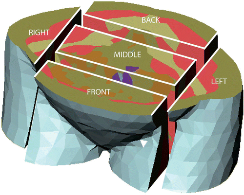
In general, the RESG state that: ‘In case of complaints from the patient, the preferred order of steering actions is: phase steering, amplitude steering, and finally, frequency steering’. In this study, we evaluated the actions in the same order. For efficiency evaluation, we divided the patient models into separate regions (). The division is based on the complaints related by patients during deep hyperthermia.
Figure 1. Partitioning of the transversal slice located at the target region into a front, middle, back, left, and right part. The central region is constrained by the smallest box containing the vagina, tumor, and uterus.
Steering is necessary in cases of overheating of healthy or tumor tissue or complaints from the patient due to hot spots. Also other non-verbal signs, like abnormal changes in pulse or blood pressure, may indicate discomfort.
In the absence of complaints, steering is used to optimize the temperature distribution; otherwise steering is used to reduce pain complaints. In the absence of complaints or healthy tissue temperatures above 43°C, and without contraindications, power is increased by 100 W every five minutes. Increase of power is ceased when the patient indicates discomfort, and is resumed only after a complaint-free period of five minutes.
Guideline 1. How to correct for unbalanced temperature distribution
Thermometry during treatment is limited. Based on the available thermometry the physician decides on the most preferable temperature distribution depending on tumor size, location, and distance to the temperature probes.
Every 5 minutes, the temperature distribution is evaluated by thermal mapping and, if necessary, antenna phase settings are adjusted to obtain a more suitable distribution.
For a centrally located target, e.g. most cervical tumors, often an evenly distributed temperature profile is desired based on the bladder, vaginal and rectal temperature. If in a thermal mapping, the bladder temperature is on average higher than the rectal temperature phase settings are adjusted to shift the focus to the rear and if the rectal temperature is higher on average than the bladder temperature, the focus is shifted in the opposite direction.
Guideline 2. How to manage deep-seated pain or pressure
Only superficial heat is perceived as heat since thermosensation is restricted to the cutis Citation[8]. Other tissues are nociceptive for temperatures above 43°C Citation[9]. Therefore, patients indicate deep-seated hot spots as pressure or dull pain.
In practice, deep-seated hot spots are often indicated as a sensation of pressure inside, diffuse pain, pain in the back, nausea, urinary urgency, or mistakenly identified as pressure by the water bolus.
After verifying that the deep-seated complaints are power related, by switching off the power and observing whether the pain reduces, phase steering in the opposite direction of the painful area is used to reduce the pain or pressure.
Guideline 3. How to alleviate superficial heat complaints
High superficial temperatures are mostly indicated by the patient as heat. Again, after verifying that the complaints are power related, the relative amplitude is reduced at the painful side, thus increasing the amplitudes on the other sides. The total power output of all antenna pairs combined remains equal.
Guideline 4. Frequency steering
When deep-seated complaints persist with all steering strategies, or if complaints are indicated at opposite sides at the same time, the frequency of the RF signal is changed. It is hypothesized that the SAR distribution is more localized at higher frequencies Citation[10]. Drawback of a more localized distribution might be the occurrence of cold spots (i.e. areas below therapeutic temperatures) in the target area. The standard operating frequency at the start of a treatment is 77 MHz for the sigma-60.
Treatment planning
Patient modeling and finite element (FE) electro-magnetic (EM) calculations are performed using AMIRA-Hyperplan (Konrad-Zuse-Zentrum fur Informationstechnik, ZIB, Berlin) Citation[11].
The workflow for modeling using a FE method in AMIRA-Hyperplan has been outlined before Citation[7],Citation[12].
In short, CT data are resampled to a slice distance of 1 cm. Automatic segmentation of tissue boundaries is performed for bone, air, muscle, and fat, based on Hounsfield units. Subsequently, all slices are manually segmented by a physician to include bladder, kidney, uterus, myelum, heart, liver, spleen, vagina, intestine, lung and stomach in addition to the automatically segmented tissues. Frequency dependent dielectric parameters for these tissues are obtained from Gabriel Citation[13]. Note that the tabulated dielectric values in literature vary for as much as 50% Citation[14]. Small and irregular structures are left out or smoothed to improve the quality of the patient model.
After segmentation the boundary surfaces are tiled by triangulation and simplified. Usually, some manual adjustments have to be made to improve the quality of the reconstructed surface. From this triangulated surface a tetrahedral grid model is generated (the patient model).
In this study the sigma-60 applicator (BSD Med. Corp., Salt Lake City) Citation[10] is used, a model of which is included in AMIRA-Hyperplan. Again, a tetrahedral grid is constructed from the applicator, the water bolus and the surrounding air volume.
The applicator grid and the patient grid are combined to give a so-called extended grid. This extended model is used for the EM calculations.
A FE method is used to solve the EM fields, followed by a full network analysis to account for coupling between the antenna pairs and the feeding networks. The calculations result in the complex EM fields per antenna-pair, which can be superposed with different antenna feeding vectors. SAR and EM-field magnitude distributions can be calculated and visualized in AMIRA-Hyperplan. According to the RESG, power has to be increased until the patient indicates pain or discomfort. For this reason, all SAR distributions for all patients were normalized to 400 W input power into the patient model.
Note however that not all power distributions acquired by superposition of the individual antenna pairs translate into possible treatment settings for the BSD. For extreme antenna settings (e.g. amplitude ratios between antenna pairs below 0.5), the network analysis may not adequately describe the cross-talk between antenna pairs Citation[16]. Further, the efficiency may be very low for extreme antenna settings, thus limiting the total power input into the patient.
Patient models
CT data of five patients with advanced cervical cancer have been processed. One of the patients had a tumor classified as FIGO stage M&M “Steering Guidelines” (IIA), two as IIB, one as stage IIIA, and one as IVA. All five tumors showed invasion of the parametria. One of them showed invasion of the lower 1/3 of the vagina, four others showed invasion into the upper 1/3 of the vagina. Further, one patient had hydronephrosis of the left kidney. No selection was applied to include patients.
CT data was acquired at a resolution of 512 × 512 pixels, 161 slices in total, corresponding to a 1 × 1 × 5 mm3 voxel cube. Patients were scanned in DHT treatment position, i.e. in the same hammock that is used in the DHT treatment set-up. The scan region ranged from 40 cm cranial to 40 cm caudal with respect to the cranial margin of the pubic bone. Patient model generation and extended model generation was successful for all five patients. The average edge length for all patient models was 2 cm.
After patient model generation, the sigma-60 applicator was placed around the patient model. Positioning in the lat-lat (LL) direction was done with respect to the center of the patient bounding-box. Positioning in the cranial-caudal direction was done at 2 cm cranial with respect to the tumor center, in agreement with the empirical guidelines for patient positioning. Positioning of the patient in the anterior-posterior (AP) direction is less clearly described in the guidelines and has been under discussion for quite a while within our clinic. Roughly, the patient's front and rear at the location of the tumor is centered in the applicator. For our patient models, we centered the applicator at the center of mass of the front, middle, and back regions of the patient as defined in the methods section below (section II D, refer to ). In our view, this approach resembles the clinical practice quite well. To check this, five of our medical assistants, who are routinely involved in patient positioning, were offered a side view of the five patient models inside the sigma-60 applicator. They were asked to center the patients inside the applicator in the AP direction according to their clinical experience. On average the patient models were positioned 2.1 cm below the position determined by the approach described above (with a mean standard deviation of 1.5 cm per patient).
In projections of the patient models are shown inside the sigma-60 applicator. The first column gives the coronal projections, the second the sagittal projections, and the last column the axial projections. The rows show the different patients that were used in this study. Note that the patient models for patient II, IV and V are extended at the legs.
Figure 2. Coronal, sagittal, and axial projections of the five patient models placed inside the sigma-60 applicator.
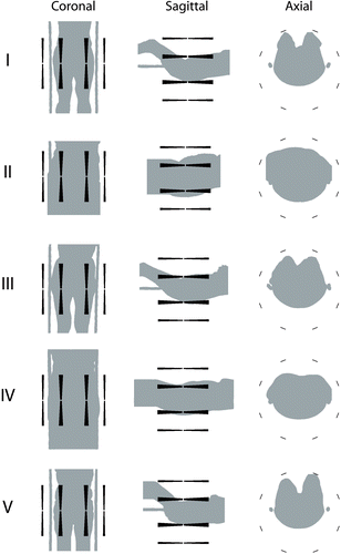
Patient centering in the LL direction is symmetrical for all patients. Note that it is difficult to determine visually whether the patient models are centered in the AP direction.
Analysis
We used SAR instead of temperature for the analyses because of the many uncertainties that surround thermal modeling for the pelvic area to date. We felt there is insufficient knowledge about which vasculature model can be used best and which perfusion coefficients should be entered in these models. Further, to accurately model perfusion, dynamic models are needed as perfusion changes with both temperature and time.
To investigate the effect of the steering actions as described in section II A, the patient models were divided into separate regions as shown in . A transversal slice through the pelvic area is defined by the region contained between the top of the uterus and the lowest part of the vagina. Within this slice a central region (middle) is assigned to the smallest box containing the uterus, tumor and vagina. In the LL direction this region was extended up to the middle of the crista iliaca and the sacro iliac joint. We refer to this region as the target region. The remaining of the transversal slice is divided in a front, back, left, and right part. The purpose of the assignment of these regions is to present a global view of what happens to the SAR distribution when different steering strategies are applied.
AMIRA-Hyperplan is not able to calculate cumulative SAR values per region of interest directly. However, dose-volume histograms (DVH) can be given per region of interest and per tissue type. A simple trapezoidal integration scheme was used to integrate the cumulative DVH. The result was multiplied with the volume of a bin to give the integrated power absorption (PA) in the specified region. This procedure was repeated for all defined regions.
Results
To evaluate the impact of the steering strategies as described by the RESG, we first address the influence of phase, amplitude and frequency steering separately. In the discussion section (section IV) of this paper we will combine these results to assess the rationale of the guidelines in comparison with the model outcomes.
Phase and amplitude steering
To get an impression of the effect of amplitude and phase steering on the SAR distribution, the effect of AP and LL phase steering is shown in for patient I. Since the effect of amplitude steering is qualitatively quite similar to phase steering, only the latter is shown. For all cross-sections the tetrahedra are filled (dark grey) that have an average SAR equal or larger than the 90% SAR percentile for synchronous phase settings and equal amplitudes. Note that the hot spots, which are present on the legs and chest, can not be observed in these pictures. Often these superficial hot spots are not power limiting since they can be cooled quite effectively. Further, bone is indicated by the yellow areas and the tumor by the magenta area. In the top row coronal cuts are plotted at the position of the supporting rods (front view). In the middle row sagittal cuts are shown at the center of the patient model, and in the bottom row axial cuts are shown through the center of the tumor (top view). In the columns the effect of 120° phase difference (which corresponds roughly to an 8 cm focus shift on the BSD console, the maximum allowed according to the RESG) is shown in the specified direction (Front: a positive phase difference of 120° of the anterior antennas with respect to the posterior antennas, Center: synchronous settings, Back: −120° phase difference, Left: a positive phase difference of 120° of the left antennas with respect to the right antennas, Right: −120° phase difference).
Figure 3. Cross-sections of the threshold SAR distributions for different phase settings for patient I. Regions with SAR levels above the 90% SAR percentile for synchronous settings are colored dark grey. Bone and target are indicated in yellow and magenta, respectively. For all steering directions, a positive phase difference of 120° is applied in the direction indicated at the bottom.
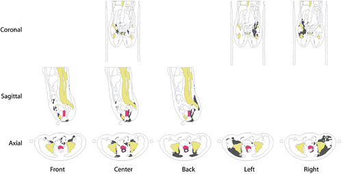
For synchronous settings, the SAR distribution looks rather scattered within the pelvis, but the center of mass of the distribution is located quite centrally. Some areas of high SAR are located in the vicinity of the target area. Further, (SAR) hot spots can be identified in the lower back associated with the lower vertebrae, at the vulva, at the pelvic bones, and anterior in the intestine right below the fat layer and at the pubic bone. When steering to the front, the focus of the SAR distribution is clearly shifted towards the front. The ventral hot spots are emphasized while removing the dorsal hot spots. Steering to the back does the opposite. The same is observed for steering in the LL direction, shifting of the average SAR focus and expression of the anatomical hot spots. As expected, phase steering in the LL direction is symmetrical. These observations also hold for amplitude steering. Stepwise phase steering calculations showed that steering in the LL directions results in a much more gradually shifting SAR distribution when compared to steering in the AP direction.
Steering efficacy
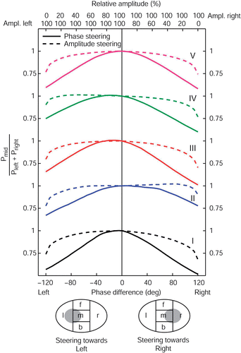
To see how efficient phase and amplitude steering are in moving power from one side to the other, the patient models were divided in separate regions, as described in section II D. Starting from synchronous phase settings and equal amplitudes, phase and amplitude steering can be used to transfer power from the center region towards one of the outer regions. In , for all five patients the effect of AP phase and amplitude steering is shown on the ratio of power deposited in the center region and power deposited in the region at the front and back. Lowering of this ratio indicates that power was transferred from the center towards the front or the back. All plots were normalized on synchronous phase settings and equal amplitudes.
Figure 4. The effect of AP phase (full lines) and amplitude steering (dashed lines) on the AP power transfer ratio for all five patient models. The AP phase difference is varied from −120° up to 120° with respect to the top antennas of the sigma−60, corresponding to a focus shift of roughly 8 cm, the maximum according to the RESG. For steering posterior, the amplitude of the bottom antennas of the sigma−60 is varied from 0 to 100%, for steering anterior, the amplitude of the top antennas are varied from 0 to 100%. All other amplitudes are kept at 100%.
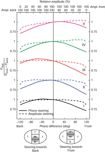
The phase difference is expressed as phase delay of the posterior antennas with respect to the anterior antennas. Again, a maximum phase difference of 120° is applied, corresponding to a focus shift of 8 cm according to the BSD console. Relative amplitudes for the anterior and posterior antennas are indicated at the top axis. Full lines show the effect of phase steering, dashed lines the effect of amplitude steering.
Firstly, we see that the change in this AP power transfer ratio is rather symmetrical with respect to central focus settings. Steering to the front or to the back has roughly the same impact on the transferal of power from the central to the outer parts. For patients I and III we see that the power transfer ratio can be slightly increased by phase steering to the back (i.e. more power is deposited in the target region compared to the outer parts). This can be explained by the fact that for all patients the target region is located a few cm posterior with respect to the applicator center.
Further, compared to amplitude steering, we see that phase steering is much more effective in transferring power from the center region to the outer parts. Only for extreme amplitude settings, e.g. in case of switching off all amplifier channels on the front or backside, is there a noticeable effect on the AP power transfer ratio. It is clear that if the aim is to shift the power distribution away from the central focus in the AP direction, phase steering is the appropriate steering action.
In we see that the same principle holds for phase and amplitude steering in the LL direction. As expected, the effect of steering in the LL direction on the LL power transfer ratio is equal for steering to the left or to the right due to the high degree of lateral symmetry. For all five patients, the tumor was located in the center of the applicator in the LL direction. Again we see that phase steering is much more effective in transferring power from the center towards the outer parts compared to amplitude steering.
Complaint reduction
Apart from the ability to shift the focus of the SAR distribution, another important feature of steering actions is to alleviate pain complaints outside the target region. For this purpose, again we divide the patient model in five transversal sections as described in section II D. To illustrate the effect of complaint reduction, we look at the reduction of power in a painful peripheral area compared to the power still present in the target (central) region. This ratio expresses the ability to reduce complaints and still heat the target region effectively.
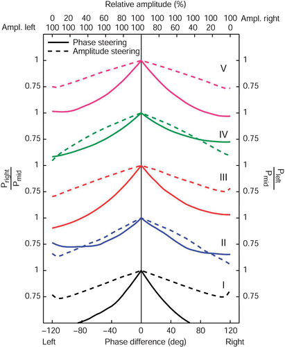
In this complaint reduction ratio is plotted for AP phase and amplitude steering. For steering posterior, i.e. in case of complaints located ventrally, this ratio is expressed by the power absorbed in the front region divided by the power absorbed in the central region. For steering anterior, i.e. in case of complaints located dorsally, the ratio is expressed by the power absorbed in the back region divided by the power absorbed in the central region. Again, all plots were normalized on synchronous phase settings and equal amplitudes.
Figure 6. The effect of AP phase (full lines) and amplitude steering (dashed lines) on the AP complaint reduction ratio for all five patient models. For steering posterior, this ratio is expressed as the power remaining in the (painful) front region compared to the power still deposited in the central (target) region. For steering anterior, this ratio is the PA in the back region divided by the PA in the central region.
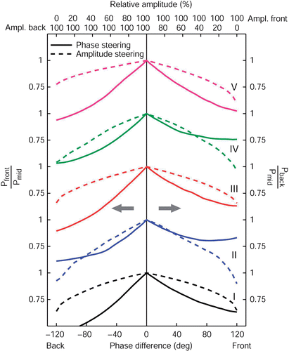
Whereas the sensitivity of the complaint reduction ratio for phase and amplitude steering is different, both steering actions can lower the ratio considerably. That is, both phase and amplitude steering are effective in lowering the PA in the outside areas and still heat the target (central) region. We observe that for all patients the relation between the complaint reduction ratio and absolute phase difference is convex and the relation between the complaint reduction ratio and the amplitude is concave.
Again these same principles hold for steering in the LL direction (). As expected, the LL complaint reduction ratio is nearly symmetrical for steering to the left or to the right. Again, this symmetry is more pronounced when compared to AP steering.
Frequency steering
In , the effect of increasing the frequency with steps of 10 MHz is shown for patient I. The effects are representative for all five patients. In the cross-sectional views red shows the regions where the SAR difference of the distribution at 85 or 95 MHz and the distribution at 75 MHz is larger than a threshold of 5.103 W/kg for a total input power of 400 W. In blue the regions are indicated were this difference is below 5.103 W/kg. On the left the profiles are shown for the difference between 85 and 75 MHz, on the right for the difference between 95 and 75 MHz. Note that the total integrated power in the patient models was the same for all three frequencies. For these calculations synchronous phase settings and equal amplitudes were used. Another possibility would have been to optimize each SAR distribution individually.
Figure 8. Cross-sections of threshold difference SAR distributions for patient I. In the left column cross-sections of the difference between SAR levels at 85 and 75 MHz, both for synchronous phase settings and equal amplitudes, are plotted. On the right, SAR differences are plotted between 95 and 75 MHz.
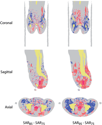
From the coronal and axial views it is clear that power deposited at the sides is transferred to the center for increasing frequency.
Further, at 85 MHz the power is removed mainly from above the pelvis, whereas at 95 MHz this region is shifted downwards. This effect of a cranial shift of the SAR focus was observed for patients I, III, and V. For patients II and IV the effect was unclear.
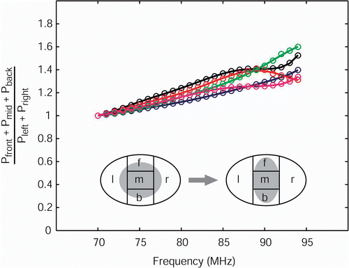
To quantify the effect of lateral confinement of the power distribution, again the five patients models were partitioned as described in section II D. As a measure for the transfer of power, the energy in the front, middle, and back regions is summed and divided by the power absorbed in the left and right part. In this confinement ratio is plotted versus frequency. The ratios are normalized at 70 MHz. The confinement ratios gradually increase with increasing frequency for all five patients. At 95 MHz there is an increase of 30–50% power transferred from the lateral parts (left, right) towards the center parts (front, middle, back).
Figure 9. LL compression of the SAR distribution in the transversal target slice as a function of frequency for all five patients normalized to 70 MHz. The compression is expressed as the PA in the front, middle, and back regions divided by the PA in the left and right regions. Lines are to guide the eye.
Discussion
In this paper we have used a treatment planning system for a somewhat unconventional purpose. Instead of using it to predict patient- and antenna-specific power distributions, we employed the HTPS to check the non-patient-specific rationale behind the empirical guidelines that have been used in our clinical practice for over 15 years now. These guidelines, based on experience, past research and patient safety, were established in a time when no HTPSs were available.
We have to stress that we are looking for qualitative similarities and differences between the guidelines and the planning results. It is not our aim to prove or disprove the correctness of either planning system or the guidelines.
Firstly, we discuss some issues concerning patient positioning and anatomical hot spots. Then the impact of the HTPS results for each guideline is treated separately, followed by some general remarks concerning the methodology.
Patient models and positioning
The stature of the five patients included in this study was rather diverse. At the transversal slice as defined in section II D, fat volume percentages for patients I to V were 13, 34, 14, 26 and, 11% respectively.
The five tumors have an average volume of 93 cm3. The average location of the tumors in the LL direction is only 2 mm off from the center of the rods. The offset in the AP direction is 1.9 cm posterior with respect to the center of mass of the front, middle and back regions in the transversal slice.
The homogeneity of the target location combined with the heterogeneity of the patient population makes the results of this study generally applicable for all cervical tumors.
As we mentioned in section M&M “Patient Models” (II C), AP positioning of the patient models inside the applicator is not trivial. In practice, measurement of the patient height inside the applicator is difficult due to absence of symmetry (like in the LL direction) or a clear reference point (like the cranial margin of the pubic bone for positioning in the caudal cranial direction). Accurate positioning is also hampered by the effect of filling the water bolus on the final position of the patient, especially in the AP direction. Seebass et al. Citation[16] showed that T90Footnote1 temperatures are most sensitive for positioning errors in the AP direction.
In our opinion, the method to center the patient models in the AP direction, as explained in section II C, comes close to the approach that is used in clinical practice. Further, there is a need for an unambiguous and highly reproducible method for AP centering in the clinic.
Hot spots
To our knowledge, an extensive review on the location of clinically observed hot spots and their frequency of occurrence during deep hyperthermia on the pelvis has not been published yet. However, Anscher et al. reported for 21 patients with locally advanced prostate cancer intolerance and pain in the hips, thighs, and pubis, corresponding to the quadrant of maximum power delivery Citation[17]. Further, Wust et al. reported for 43 locally advanced tumors of different locations a topographical classification of local side effects including their frequencies Citation[18]. Their list overlaps the hot spot areas we qualitatively identified for our five patients based on the SAR distribution plots (compare ). These areas include: lower ventral abdomen, ventral adipose tissue and the suprapubic region. Further, dorsally located, the sacral region. Also hot spots at the perineum/vulva could be identified both clinically and in our model calculations. Hot spots on the inside and on top of the thighs were also observed but are not shown in . Hot spots at skin folds, rima ani and the inguinal region were not found probably due to the coarse level of modeling.
The hot spots listed above are considered to be anatomical, since they show higher SAR values than their immediate surroundings, and their location cannot be gradually shifted by steering actions.
In this paper we did not consider the effect of these anatomical hot spots on the steering strategies. That is, in section Steering Efficiency (III B) and Complaint Reduction (III C) we focused on the power transfer between a target and four rather large peripheral regions. Although we think this is an adequate description, the effect of the different steering strategies may be different when we consider the effect for specific, power limiting hot spots.
Implications for the guidelines
Guideline 1. How to correct for unbalanced temperature distribution
For a typical patient with cervical cancer, three intraluminal temperature probes are used, one in the bladder, one in the vagina, and one in the rectum. These probes are all located in the mid-sagittal plane.
To change the temperature distribution, we can use either phase or amplitude steering. Phase differences and amplitude settings are compared by the maximum change allowed by the RESG.
Restrictions to the allowed phase or amplitude differences are based on clinical experience and not imposed by any technical limitations of the current BSD 2000–3D system. The maximum allowed phase difference is approximately 120°, corresponding to an absolute shift of ∼8 cm of the SAR focus in an abdomen equivalent phantom according to the BSD console. The maximum decrease of amplitude per channel is 50%. However, in case of high reflected power or malfunctioning of the equipment, it is allowed to proceed with the specific channel switched off (i.e. with 0% amplitude). During the last five years, for five patients the sigma-60 applicator was operated the entire treatment with only three channels.
Instead of balancing the amplitude ratios, amplitude steering is accomplished by simply lowering the amplitude on one side while keeping the total power the same. This idea is closely associated with how the BSD console is operated, where also the relative amplitude is changed with respect to the three other channels.
For a centrally located tumor, especially the bladder and rectal temperatures are balanced; the vaginal temperatures are often somewhat lower (for a population of 22 patients Fatehi et al. Citation[19] reported all lumen T50 for bladder, vagina, and rectum of 40.6, 40.0 and 40.5 respectively).
From we see that in general phase steering is more effective in transferring power from the central region towards the front or back compared to amplitude steering. That is, the position of the center of mass of the SAR distribution (the SAR focus) is much more sensitive for changes in phase difference than it is for changes in amplitude settings. From we see that the same holds for steering in the LL direction.
We conclude that phase steering is the appropriate steering action in case of temperature differences.
Guideline 2. How to treat deep-seated pain or pressure
The implications of the HTPS outcomes in the case of deep-seated pain or pressure are similar to the first guideline. To reduce deep-seated complaints, the power absorbed in the painful region has to be removed. This can be accomplished by shifting the SAR focus away from this region. As we stated above, it was observed that for a centrally located region the global power distribution can be effectively shifted with phase steering.
Guideline 3. How to alleviate superficial heat complaints
For a centrally located tumor, peripheral complaints, often indicated as heat, may still be power limiting. shows that steering in the opposite direction, away from the painful region can be done effectively with either phase or amplitude steering. For both types of steering the complaint reduction ratio can be decreased. However, phase steering shifts the SAR focus away from the target region, thus lowering the efficiency (fraction of the total power input into the patient that is absorbed in the target region). Thus we conclude that amplitude steering is appropriate in case of superficial complaints. From we see that the same holds for steering in the LL direction.
Note that the peripheral regions we defined in section II D extend up to the target region. From additional calculations it was found that the effect of peripheral complaint reduction is even more pronounced when focusing on peripheral regions that are located more superficially.
Guideline 4. Frequency steering
In Rotterdam, the standard operating frequency for the sigma-60 is 77 MHz. Within the range of possible BSD 2000–3D frequencies, 75–120 MHz, this choice is rather low. Historically, higher standard operating frequencies were not considered for several reasons. The idea is that a low frequency implies a larger heating volume, thus avoiding cold spots in the target volume and possibly pre-heating blood that enters the tumor. Further, high frequencies resulted in a high reflected power and in instabilities. The guidelines now limit the frequency range to 75–90 MHz.
In and the effect of an increase in frequency on the SAR distribution is illustrated. Remarkably, the compression of the SAR distribution with increasing frequency is much more apparent in the LL direction than in the AP direction. Further, we see a clear longitudinal shift of the SAR distribution with changing frequency. No clear compression of the SAR distribution is observed in this direction.
This is in agreement with the findings of van Rhoon et al. Citation[8]. They reported that the size of the longitudinal 50% iso-SAR area in a cylindrical phantom is independent of the operating frequency (within a range of 70–100 MHz). This can be attributed to the limited distance of the antennae to the load. In this case the extension of the SAR distribution is merely dominated by the antenna lengths. Further, they found the extension of the SAR distribution in the axial direction to be dependent on the frequency. A decrease of 15.3 to 9.7 cm was reported when increasing the frequency from 70 to 100 MHz.
Seebass et al. Citation[16] and Paulsen et al. Citation[20] also treated the effect of a frequency increase for antenna configurations resembling the sigma-60 applicator (one antenna ring with four antenna pairs). Both studies showed clearly that for an increasing number of antennas and antenna rings, higher frequencies (>100 MHz) result in higher gain factors. Surprisingly, for the specific sigma-60 configuration and for centrally located tumors, they found decreasing gain factors. Paulsen did not report a longitudinal shift in SAR distribution with increasing frequencies from 100 to 150 or 200 MHz. However, neither of these studies focused on frequencies in the range of 70–100 MHz.
It is evident that the idea of increasing the frequency in case of multiple peripheral complaints at opposite locations has to be adjusted. Based on the model outcomes we can be more specific when an increase in frequency is appropriate. First of all, according to , increasing the frequency from 77 MHz will result in increased SAR levels within the pelvis. This would suggest that higher frequencies would always be preferable. However, SAR levels are also increased at the anterior and posterior hot spot locations. From this work we cannot conclude whether a higher frequency than 77 MHz is in general more profitable.
However, for three of the patients we found that an increase of 77 to 85 MHz resulted in less power in the back. Thus for specific complaints in the back, increasing the frequency to 85 MHz would be an option. Further, for pressure or heat at the lateral hip regions, the model predicts that an increase in frequency would be beneficial.
Final remarks
A general assumption behind the steering guidelines and the partitioning described in section II D, is that the steering actions affect only the SAR distribution in the transversal plane. From it can be seen that this is valid for phase (and amplitude) steering. However, for frequency steering (), there is a considerable longitudinal effect. This effect is also visible in at high frequencies, where power is also transferred out of and into the transversal plane. It should be stressed that these effects, that are quite patient specific, have to be taken into account when considering frequency steering, and may cause unexpected hot spots.
Further, when performing steering actions, the efficiency of power input into the patient may also be changing. This requires that power should always be increased until complaints occur, or at least one should verify that average temperatures near the target region are not decreasing. Choosing the most inefficient steering parameters is not a sensible strategy to avoid complaints.
Conclusions
In this work we evaluated the Rotterdam empirical steering guidelines with model calculations using AMIRA-Hyperplan as a treatment planning system (HTPS).
For all steering actions it is assumed that input power is increased until complaints occur.
Four guidelines were investigated. The first one states that phase steering is appropriate to balance intraluminal temperatures. Model calculations showed that the power distribution can be effectively shifted peripherally by increasing phase differences of opposite antenna pairs. This type of steering action is also to be used in the case of deep-seated pain complaints or other discomfort, which is stated in the second guideline.
Further, it was found that to alleviate superficial complaints of heat or pressure, reducing amplitude is indeed the proper action of choice.
The last guideline states that frequency has to be increased from 77 MHz upwards in case of multiple, opposite painful regions that cannot be avoided by phase or amplitude steering. The HTPS calculations confirmed compression of the SAR distribution, mainly in the LL direction. For complaints in the lower back, a frequency increase should be considered.
The results of the HTPS are in close agreement with the empirical steering guidelines.
Acknowledgements
This research was supported by the Dutch Cancer Society (DCS grant 2003–2884).
Declaration of interest: The authors report no conflicts of interest. The authors alone are responsible for the content and writing of the paper.
Notes
Notes
1. T90 is the lower threshold temperature with 90% of the temperature readings have a value higher than this threshold.
References
- van der Zee J, Gonzalez Gonzalez D, van Rhoon GC, van Dijk JD, van Putten WL, Hart AA. Comparison of radiotherapy alone with radiotherapy plus hyperthermia in locally advanced pelvic tumours: A prospective, randomised, multicentre trial. Dutch Deep Hyperthermia Group. Lancet 2000; 355: 1119–1125
- Franckena M, Stalpers LJA, Koper PCM, Wiggenraad RGJ, Hoogenraad WJ, et al. Long-term improvement in treatment outcome after radiotherapy and hyperthermia in locoregionally advanced cervix cancer: An update of the Dutch Deep Hyperthermia Trial. Int J Radiat Oncol Biol Phys 2008; 70(4)1176–1182, 2008
- Franckena M, Lutgens LCHW, Koper PCM, Kleynen CE, van der Steen-Banasik EM, et al. Radiotherapy and hyperthermia for treatment of primary locally advanced cervix cancer: Results in 378 patients. Int J Radiat Oncol Biol Phys 2008, In Press
- Quesson B, de Zwart JA, Moonen CT. Magnetic resonance temperature imaging for guidance of thermotherapy. J Magn Reson Imaging 2000; 12: 525–533
- van Rhoon GC, Wust P. Introduction: Non-invasive thermometry for thermotherapy. Int J Hyperthermia 2005; 21: 489–495
- Clegg ST, Das SK, Zhang Y, Macfall J, Fullar E, Samulski TV. Verification of a hyperthermia model method using MR thermometry. Int J Hyperthermia 1995; 11: 409–424
- Gellermann J, Wust P, Stalling D, Seebass M, Nadobny J, Beck R, Hege H, Deuflhard P, Felix R. Clinical evaluation and verification of the hyperthermia treatment planning system hyperplan. Int J Radiat Oncol Biol Phys 2000; 47: 1145–1156
- Graven-Nielsen T, Arendt-Nielsen L, Mense S. Thermosensitivity of muscle: High-intensity thermal stimulation of muscle tissue induces muscle pain in humans. J Physiol 2002; 540: 647–656
- Tominaga M, Caterina MJ. Thermosensation and pain. J Neurobiol 2004; 61: 3–12
- Van Rhoon GC, Van Der Heuvel DJ, Ameziane A, Rietveld PJ, Volenec K, Van Der Zee J. Characterization of the SAR-distribution of the Sigma-60 applicator for regional hyperthermia using a Schottky diode sheet. Int J Hyperthermia 2003; 19: 642–654
- Stalling D, Seebass M, Hege HC, Wust P, Deuflhard P, Felix R. Hyperthermic Oncology 1996. Vol. II: Papers, Proc. 7th Int. Congress on Hyperthermic Oncology., C Franconi, G Arcangeli, R Cavaliere. Tor Vergata, Rome 1996; 552–554
- Sreenivasa G, Gellermann J, Rau B, Nadobny J, Schlag P, Deuflhard P, Felix R, Wust P. Clinical use of the hyperthermia treatment planning system HyperPlan to predict effectiveness and toxicity. Int J Radiat Oncol Biol Phys 2003; 55: 407–419
- Gabriel S, Lau RW, Gabriel C. The dielectric properties of biological tissues: III. Parametric models for the dielectric spectrum of tissues. Phys Med Biol 1996; 41: 2271–2293
- Van de Kamer JB, Van Wieringen N, De Leeuw AA, Lagendijk JJ. The significance of accurate dielectric tissue data for hyperthermia treatment planning. Int J Hyperthermia 2001; 17: 123–142
- Wust P, Beck R, Berger J, Fahling H, Seebass M, Wlodarczyk W, Hoffmann W, Nadobny J. Electric field distributions in a phased-array applicator with 12 channels: Measurements and numerical simulations. Med Phys 2000; 27: 2565–2579
- Seebass M, Beck R, Gellermann J, Nadobny J, Wust P. Electromagnetic phased arrays for regional hyperthermia: Optimal frequency and antenna arrangement. Int J Hyperthermia 2001; 17: 321–336
- Anscher MS, Samulski TV, Dodge R, Prosnitz LR, Dewhirst MW. Combined external beam irradiation and external regional hyperthermia for locally advanced adenocarcinoma of the prostate. Int J Radiat Oncol Biol Phys 1997; 37: 1059–1065
- Wust P, Stahl H, Löffel J, Seebass M, Reiss H, Felix R. Clinical, physiological and anatomical determinants of radiofrequency hyperthermia. Int J Hyperthermia 1995; 11: 151–167
- Fatehi D, van der Zee J, van der Wal E, Van Wieringen WN, Van Rhoon GC. Temperature data analysis for 22 patients with advanced cervical carcinoma treated in Rotterdam using radiotherapy, hyperthermia and chemotherapy: A reference point is needed. Int J Hyperthermia 2006; 22: 353–363
- Paulsen KD, Geimer S, Tang J, Boyse WE. Optimization of pelvic heating rate distributions with electromagnetic phased arrays. Int J Hyperthermia 1999; 15: 157–186
