
Abstract
Purpose: Microwave ablation (MWA) applicators capable of creating directional heating patterns offer the potential of simplifying treatment of targets in proximity to critical structures and avoiding the need for piercing the tumour volume. This work reports on improved directional MWA antennas with the objectives of minimising device diameter for percutaneous use (≤ ∼13 gauge) and yielding larger ablation zones.
Methods: Two directional MWA antenna designs, with a modified monopole radiating element and spherical and parabolic reflectors are proposed. A 3D-coupled electromagnetic heat transfer with temperature-dependent material properties was implemented to characterise MWA at 40 and 77 W, for 5 and 10 min. Simulations were also used to assess antenna impedance matching within liver, kidney, lung, bone and brain tissue. The two antenna designs were fabricated and experimentally evaluated with ablations in ex vivo tissue at the two power levels and treatment durations (n = 5 repetitions for each group).
Results: The computed specific absorption rate (SAR) patterns for both antennas were similar, although simulations indicated slightly greater forward penetration for the parabolic antenna. Based on simulations for antennas inserted within different tissues, the proposed antenna design appears to offer good impedance matching for a variety of tissue types. Experiments in ex vivo tissue showed radial ablation depths of 19 ± 0.9 mm in the forward direction for the applicator with spherical reflector and 18.7 ± 0.7 mm for the applicator with parabolic reflector.
Conclusion: These results suggest the applicator may be suitable for creating localised directional ablation zones for treating small and medium-sized targets with a percutaneous approach.
Introduction
Image-guided thermal ablation has emerged as a leading treatment modality for percutaneous thermal ablation of tumours, most commonly used in the liver [Citation1], lung [Citation2], kidney [Citation3], and bone [Citation4]. Ablation is also in clinical use for controlled thermal treatment of cardiac arrhythmias, and thermal tissue modification. Compared to other percutaneous ablation modalities – lasers, radiofrequency, ultrasound – microwaves offer the advantage of being able to travel through charred tissue and vapour, yielding higher tissue temperature, larger ablation zones, and better efficacy close to vessels [Citation5,Citation6]. The electric field radiated by the ablation antenna is absorbed within lossy tissue, leading to heating. Passive heat transfer due to thermal conduction and transport of hot gases contribute to further growth of the ablation zone. Currently available microwave ablation (MWA) systems for clinical use operate at 915 MHz or 2.45 GHz [Citation7], while systems operating at other frequencies are under investigation [Citation8,Citation9]. The treatment goal during tumour ablation is to raise the temperature of the targeted tumour and a 1-cm margin of healthy tissue to cytotoxic temperatures (>55 °C), while minimising thermal damage to non-targeted tissue [Citation10]. Although tumour ablation has comparable outcomes to surgical resection for small tumours [Citation10,Citation11] local recurrence rates remain considerably higher for large tumours (>3 cm in diameter). Incomplete thermal destruction of tumours and failure to establish an adequate margin is believed to be a cause for these high recurrence rates, due to the limitations of available heating technology as well as technical difficulties associated with accurate device placement relative to targets. Other contributing factors include a limited understanding of the physical processes during ablation and their influence on treatment outcome (e.g. tissue shrinkage) and the lack of real-time monitoring of the ablated area [Citation10,Citation12,Citation13]. The more aggressive underlying biology associated with larger tumours may also play a role [Citation14]. Technologies affording more customisable ablation zone profiles may enable safer and more efficacious ablation of targets, especially those in proximity to critical structures.
Currently available MWA devices in clinical use have cylindrically symmetric radiation patterns, with no control of energy deposition along the angular expanse. To control undesired heating along the antenna length, several antenna designs incorporate sleeves or chokes [Citation15–18]. Active cooling is also frequently used to limit axial heating and increase the power handling capacity of thin coaxial cables [Citation19,Citation20]. Most currently available ablation systems operate ‘open-loop’, although some recent systems have incorporated some feedback control based on changes in tissue state during ablation [Citation18,Citation21]. Among other energy modalities for thermal ablation, catheter-based ultrasound devices [Citation22–25] and lasers [Citation26] offer some control of directionality in the energy deposition pattern. An additional benefit of catheter-based ultrasound technology is the ability to actively control heating along the applicator length.
Ablation devices allowing directional control of energy offer several advantages for conformal tissue ablation. First, directional applicators yield the potential to safely ablate targets in the vicinity of critical structures by positioning the ablation applicator to radiate in a direction pointing away from the structures to be spared. Such an approach may provide additional degrees of freedom for planning device insertion paths, compared to conventional devices with cylindrically symmetrical heating patterns. Second, directional ablation devices may mitigate the need to pierce the targeted tumour, and thus may reduce the risk of tumour seeding during device positioning [Citation27]. Finally, since the risk of spread of tumour micrometastases is greatest along the tumour periphery, heating targets with multiple directional antennas along the tumour periphery whilst aiming inwards towards the tumour centre may increase the likelihood of achieving a desired safety margin [Citation28].
Previous studies have investigated microwave devices with directional radiation patterns (i.e. asymmetric along the angular expanse) for thermal therapy applications. A 915 MHz antenna for transurethral prostate hyperthermia was achieved by incorporating a microwave-absorbing fluid within the ablation catheter. By asymmetrically positioning the antenna within the catheter, microwave energy in some directions was more heavily absorbed into the fluid, affording greater energy deposition within tissue in the preferred direction [Citation29]. This directional technology has been employed in pre-clinical studies investigating the use of microwave thermal therapy for transurethral treatment of benign prostatic hyperplasia [Citation30]. Another approach for creating directional radiation patterns is through the use of a reflector to shield tissue along a fraction of the angular expanse, and thereby constrain the majority of the microwave radiation to a preferred direction. Debicki et al. employed this approach to design a transrectal microwave applicator for prostate thermal therapy [Citation31]. We recently presented a directional MWA antenna designed to operate at 2.45 GHz [Citation32], affording energy deposition to about half of the angular expanse, with minimal backward radiation. Limiting the directional energy deposition to a preferred direction was achieved by augmenting a coaxial monopole antenna with a metallic hemi-cylinder to serve as a reflector/shield. In order to provide cooling along the length of the applicator and also to reduce the dimensions of the proposed antenna design, water (ɛr ∼78 at 2.45 GHz) was circulated between the antenna and the reflector, serving as a high permittivity material to decrease the effective antenna wavelength. The proof-of-concept directional MWA design had an outer diameter of ∼3.5 mm.
In this paper we investigate technical improvements to the directional MWA antenna design reported in McWilliams et al. [Citation32] with the objectives of minimising the device diameter to be suitable for percutaneous use (i.e. diameter ≤13 gauge or 2.5 mm outer diameter (OD) [Citation6] and yielding larger ablation zones. This was achieved through the use of thinner coaxial cables, shifting the antenna radiating element towards the catheter inner-wall, thereby enabling greater energy coupled to the targeted tissue, while maintaining a good impedance match. Finite element method (FEM) simulations facilitated analysis of changes in the antenna specific absorption rate (SAR) pattern during heating. Simulations also demonstrated good impedance matching of the proposed antennas when inserted within a variety of tissue types. Experimental evaluations in ex vivo tissue indicated no statistically significant differences in ablation dimensions for devices employing a spherical or parabolic reflector; both devices yielded larger ablation zones in the forward direction compared to the previously reported design [Citation32].
Methods
Proposed applicators
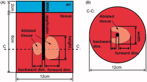
is a schematic depiction of the directional MWA antenna incorporating a hemi-cylindrical reflector, as described in McWilliams et al. [Citation32]. This applicator is tuned to operate at 2.45 GHz by setting the length of the monopole antenna element to 6 mm. The device also incorporates water circulating through its shaft. The circulating water provides 1) active cooling to mitigate heating along the applicator length, and 2) a high-dielectric constant medium to reduce the wavelength, thereby limiting overall applicator size. To further reduce the diameter of this applicator we have investigated geometry modifications/augmentations to the antenna radiating element and reflector in terms of shape and relative position. Two different applicator designs are proposed, one with a spherical reflector () and one with a parabolic reflector ().
Figure 1. Geometry of directional MWA antennas with longitudinal view (top row), and transverse view taken through a cross section (dotted line C–C) of (A) the MWA applicator reported in McWilliams et al. [Citation32], (B) the proposed design with a spherical reflector, and (C) the proposed design with a parabolic reflector. Modifications to the reflector and monopole element are shown in the longitudinal view with thick dashed lines.
![Figure 1. Geometry of directional MWA antennas with longitudinal view (top row), and transverse view taken through a cross section (dotted line C–C) of (A) the MWA applicator reported in McWilliams et al. [Citation32], (B) the proposed design with a spherical reflector, and (C) the proposed design with a parabolic reflector. Modifications to the reflector and monopole element are shown in the longitudinal view with thick dashed lines.](/cms/asset/5bf5a81f-338a-49ca-aef3-4941ec50c5ae/ihyt_a_1195519_f0001_b.jpg)
As shown in , the radiating monopole is bent further away from the reflector all the way to the catheter wall such that 4 mm retains parallel alignment with respect to the antenna shaft edge. The rationale for investigating this placement of the radiating monopole in close proximity to the catheter wall and closer to the tissue is that it would allow a larger portion of the reactive near field with high energy density to be coupled into the tissue, reducing the loss of energy in the cooling water channel. While this modification has the potential for increasing the heating rate and ablation zone size in the forward heating direction, it may also increase the portion of tissue along the angular expanse which is affected directly by the EM field from the radiating monopole tip, and hence introduces increased heating behind the applicator.
Two geometric modifications of the reflector were therefore investigated to mitigate the anticipated increase in backward heating. In the case of the spherical reflector design, the reflector position is shifted to the inner wall of the catheter away from the preferred radiation direction (see , h1 = 2.1 mm). Positioning the reflector in this fashion is anticipated to increase the electromagnetic energy coupled to tissue in the forward direction, as well as afford increased shielding in the reverse direction by extending the angular coverage of the reflector. In the case of the parabolic reflector design, the dimension h in was retained (i.e. equivalent to h for the spherical reflector design), but the shape of the reflector was modified to follow the parabolic expression [Citation33] in the cross-sectional cut:
(1)
where x and y are coordinates in cross-sectional cut in and distance from the reflector wall to the focal point F is defined by
(2)
where D is the width of the reflector which corresponds to the dimension w in , and angle θ0 was chosen empirically as 30°. This shape parametrisation led to the selection of h2 = 1.3 mm. Consequently, the portion of directly heated tissue behind the applicator decreased in both reflector cases. Dimensions w and h are 2.2 mm and 1.2 mm, respectively, for both proposed reflectors.
Proof-of-concept applicators were fabricated for experimental evaluation following the procedure previously described in McWilliams et al. [Citation32], with the following modifications. The monopole antenna was fabricated with UT-34 semi-rigid coaxial cable (154-00002, Micro-coax, Philadelphia, PA, USA). Stainless steel metallic tubing with 1.82 mm (OD) and 1.37 mm inner diameter (ID) (McMaster-Carr, Elmhurst, IL, USA) was used to implement the reflector and serve as a guidance channel for the water cooling. The monopole radiating tip and reflector shape were modified with hand tools to meet the desired geometry requirements. Polyimide tubing with 2.46 mm (OD) (∼13 gauge) and 2.303 mm (ID) (American Durafilm, Holliston, MA) was used as a catheter to enclose the applicator, and provide a return flow path for water.
Computational model
A simulation-based approach was employed to determine antenna dimensions and analyse antenna performance. A coupled 3D electromagnetic-heat transfer model, incorporating temperature-dependent tissue electrical and thermal properties, was implemented using the FEM to calculate the electric fields and transient temperature profiles in tissue, and to estimate the induced thermal damage following microwave heating. The model was employed to solve the Helmholtz electromagnetic wave equation:
(3)
where E is the electric field complex time-harmonic vector [V m−1], β0 is the wavenumber in free space [m−1], ɛr is relative permittivity, σ is electric conductivity [S m−1], ω is angular frequency [rad s−1] and ɛ0 is the permittivity of free space [F m−1]. Nominal values of relative permittivity and electric conductivity at 37 °C as well as types of their temperature dependencies are provided in . Temperature-dependent dielectric properties of tissue, using the models proposed by Ji and Brace [Citation34], and Lopresto et al. [Citation35] were incorporated. The initial value of electric field was set to 0 V m−1 in all simulation domains. Furthermore, a first order scattering boundary condition which approximates Sommerfeld radiation condition was used at all outer boundaries of simulated space:
(4)
where n is normal vector to the boundary. The time-averaged electromagnetic losses are calculated from the computed electric field using EquationEquation 5
(5) .
(5)
Table 1. Tissue biophysical properties employed in finite element method simulations.
Transient temperature profiles within the tissue were computed using Pennes’ [Citation36] bioheat equation,
(6)
where ρ c is the volumetric heat capacity [J m−3K−1], T is the temperature [K], k is the thermal conductivity [W m−1K−1], ωbl is the blood perfusion [W m−3K−1], and Tbl is the physiological temperature of the blood (i.e. 37 °C). The baseline values of tissue thermal properties and their temperature dependency are summarised in .
The initial temperature was set to 37 °C in the whole simulation domain. A thermal insulation boundary condition was set at the outer simulation boundaries.
(7)
To approximate the effects of circulating water through the applicator shaft, a fixed temperature boundary condition (T = 20 °C) was employed as compromise between ideal cooling, and some electromagnetic absorption by the circulating chilled water. The thermal damage induced in tissue following ablation was estimated as a function of time and temperature using the Arrhenius model,
(8)
where Ω (T) is a dimensionless damage parameter, A is a frequency factor (5.51 ċ 1041 [s - 1), Ea is an energy barrier (2.769 ċ 105 J mol - 1), R is the gas constant (8.3143[J mol−1 K−1]), and τ is the total time for which the thermal damage was accumulated in the tissue. Values of A and Ea parameters were chosen based on Pearce’s study [Citation39] targeted on estimation of whitening in pig liver during ablation. A threshold value of Ω = 1, corresponding to ∼63% completion of thermal damage process, was chosen as a threshold for estimating the extent of the ablation zone.
The coupled electromagnetic–bioheat transfer model and tissue thermal damage analysis was implemented with COMSOL Multiphysics (v5.1, Burlington, MA) and MATLAB (R2015a, MathWorks, Natick, MA). An implicit transient solver was used, with a maximum time step of 5 s. At each time step, tissue electrical and thermal properties were updated using the temperature-dependent parameterisations summarised in . We investigated two power levels being applied to the antenna input port, specifically 40 and 77 W. The effects of varying blood perfusion ωbl levels (0, 35,000 and 60,000 W m−3 K−1) on applicator performance were also investigated. illustrates the model geometry and dimensions used to characterise the ablation zone pattern.
Figure 2. Illustration of the geometry employed for computational models: (A) longitudinal view along the length of the applicator, and (B) transverse view taken through a cross section (dotted line C–C).
The density of the tetrahedral mesh was highest at the input port (maximum element edge length of 0.2 mm), coarser around the antenna (0.4 mm edge length) and the largest element edge length in the simulation domain was 2 mm (for tissue located more than 20 mm from the antenna, and in the air regions) providing a reasonable balance between spatial resolution and computational complexity. The number of degrees of freedom in each model was ∼4.8 million on average, and the average computation time for one simulation was ∼18 h on a machine with Intel(R) Core(TM) i5-3570 CPU running at 3.4 GHz, with 16 GB RAM. When extracting temperature maps at specified times, we used interpolation at the rectangular grid with a spatial step of 0.25 mm.
In addition to the coupled electromagnetic-thermal simulations, another set of computations was performed to assess antenna impedance matching (as measured by the reflection coefficient, s11) in a variety of tissue types and over the frequency range 2–3 GHz. These computations involved only electromagnetic simulations and were conducted to determine whether antenna dimensions would need to be tuned to match the electrical properties of varying tissue types. The following tissues were considered: liver, kidney, muscle, bone (cancellous and cortical), lung (inflated), and brain (grey matter and white matter). The dielectric properties of these tissues at 2.45 GHz were taken from Gabriel et al. [Citation37].
Experimental evaluation
The impedance matching of fabricated antennas was evaluated by antenna reflection coefficient measurements with an HP8753D (Keysight, Santa Rosa, CA) vector network analyser, with the test device loaded within tissue at room temperature. To assess the variability of antenna matching, we carried out measurements at five locations within each tissue type. The following tissues were considered: bovine liver, porcine muscle and porcine lung. The efficacy of the applicators’ ability for creating thermal ablation zones was evaluated with experiments in ex vivo bovine liver, a commonly used experimental model for benchmarking ablation applicator. Five ablations were performed with each applicator design (design with modified radiating tip and spherical reflector, and design with modified radiating tip and parabolic reflector) under the following experimental conditions: 5 and 10 min ablation duration; 40 and 77 W power levels at the applicator input port, yielding a total of 40 experiments.
During experimental ablations, microwave power was supplied using an HP 8648C signal generator, and a solid-state amplifier (RFCore, RCA0527H49A, Karmel Tech, Korea). A Bird 5012A (Solon, OH) power meter was connected in line with the antenna to measure forward and reflected power during experiments. Fresh bovine liver tissue samples were used for all experiments. Excised livers were transported from a local abattoir to the lab in sealed plastic bags placed on ice. Livers were warmed up to ∼30–35 °C while placed in sealed plastic bags within a temperature-controlled water bath. A custom 3D printed fixture was fabricated to ensure reliable device placement.
The discoloured extents of each experimental tissue sample were measured following tissue heating. Specifically, the following ablation dimensions illustrated in were recorded: 1) radial extent of ablation zone in the direction of radiation from the applicator (forward dimension), 2) radial extent of the ablation zone in the reverse direction (backward dimension), 3) width of the ablation zone, and 4) height of the ablation zone. Dimensions of the ablation zones for each of the proposed applicators were statistically compared with the use of one-way analysis of variance and its post-hoc Scheffe’s test at a 5% level of significance.
Results
Simulation results
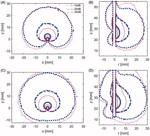
shows the simulated SAR profiles for directional MWA antennas incorporating spherical reflectors () and parabolic reflectors (). To comparatively assess how the SAR profiles of the antennas change during the course of an ablation as tissue electrical properties change, SAR profiles were computed at the onset of ablation (t = 0 s) and immediately before the ablation is terminated (t = 600 s). SAR profiles are illustrated with the −10, −20, and −30 dB contours, normalised to the peak SAR value at t = 0 s (for each antenna).
Figure 3. Specific absorption rate at 77 W: (A) X–Y plane and (B) Y–Z plane for applicator with the spherical reflector at the start of heating (thick blue lines) and after 10 min heating (slim red lines), and C) X–Y plane and D) Y–Z plane for applicator with the parabolic reflector at the start of heating (thick blue lines) and after 10 min heating (slim red lines). In all subfigures, solid lines represent –10 dB contours, dash-and-dot lines –20 dB contours and dotted lines –30 dB.
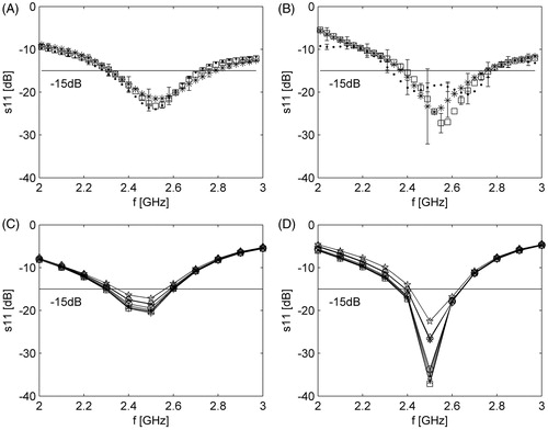
shows experimentally measured and simulated reflected coefficients for both applicator designs over the 2–3 GHz frequency range.
Figure 4. Measured and simulated antenna reflection coefficient over the 2–3 GHz range. (A) Measured reflection coefficient for the applicator with spherical reflector. (B) Measured reflection coefficient for the applicator with parabolic reflector. (C) Simulated reflection coefficient for the applicator with spherical reflector. (D) Simulated reflection coefficient for the applicator with parabolic reflector. Symbols for tissues are as follows: (A, B) → ·, liver; *, lung (inflated); □, muscle; (C,D) → ·, liver; *, lung (inflated); □, muscle; ○, brain (white matter); ×, brain (grey matter); +, kidney; ⋄, bone (cancellous); ⋆, bone (cortical).
shows simulated temperature profiles for a model employing no blood perfusion (i.e. ex vivo tissue), overlaid with extents of the ablation zones estimated by means of Arrhenius thermal damage model contours for three different perfusion levels.
Figure 5. Temperature maps after 10 min ablation with 77 W power. Solid black contours correspond to the blood perfusion levels: 0 (0 W m−3K−1), 1 (35,000 W m−3K−1) and 2 (60,000 W m−3K−1) (from outer region inwards). (A) X–Y plane and applicator with spherical reflector, (B) Y–Z plane and applicator with spherical reflector, (C) X–Y plane and applicator with parabolic reflector and (D) Y–Z plane and applicator with parabolic reflector.
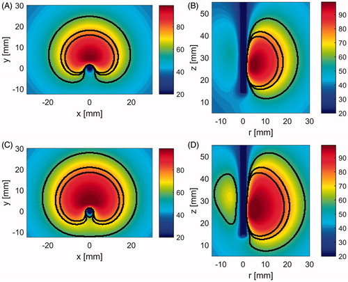
After 10 min heating with 77 W at the applicator input port and no perfusion, computational models predicted maximal ablation zone extents with dimensions 23.3 mm (forward dimension), 39 mm (width), 36.3 mm (height) and 7 mm (backwards) for the applicator with spherical reflector, and 26.5, 45, 44.3 and 12.25 mm respectively for the applicator with parabolic reflector. These ablation dimensions are to be directly compared with the available data from the former applicator evaluation, that is 19.5 (forward dimension), 32.5 (width) and 3.25 mm (backwards). For a nominal perfusion level of 35,000 W m−3K−1, the above stated ablation dimensions decreased to 16.5, 27.5, 26 and 3.25 mm for an applicator with spherical reflector and 19.5, 32.5, 32.5 and 6.5 mm for an applicator with parabolic reflector. The smallest ablation zones were observed for simulations with a nominal perfusion level of 60,000 W m−3K−1 with respective dimensions 14.25, 23.5, 22.5 and 2.25 mm for the applicator with a spherical reflector and 17, 28.5, 28.5 and 4.75 mm in the case of the applicator with a parabolic reflector.
Experimental results in ex vivo tissue
summarises measured dimensions of experimental ablation zones in ex vivo bovine liver. provides an illustration of the ablation zone dimensions listed in .
Table 2. Dimensions of experimental ablation zones in ex vivo tissue for improved applicators.
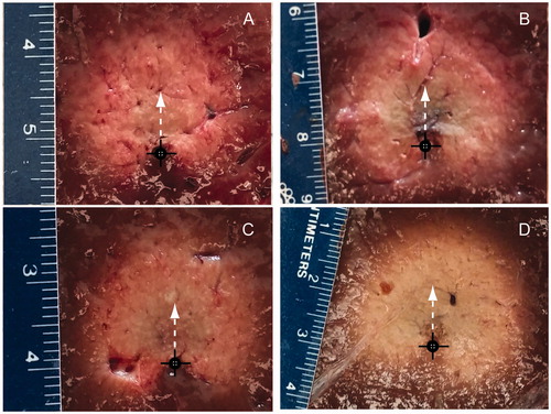
shows example ablation zones created in ex vivo bovine liver with both antenna designs following 10 min ablations at 40 W and 77 W. Black circles mark the applicator position during the experiment, and white arrows indicate the direction with maximal extent of the ablation zone (i.e. main radiation direction).
Figure 6. Experimental ablation zones created in ex vivo bovine liver using an applicator with a spherical reflector with 40 W power (A), and 77 W power (B), and using an applicator with a parabolic reflector with 40 W power (C), and 77 W power (D). Black cross indicates the position of antenna and white arrow the direction of maximal radiation.
Discussion
This study was undertaken to perform an in-depth analysis of reflector-based antenna designs, for creating directional MWA patterns. Adaptations to a previously proposed 3.5 mm directional MWA antenna were investigated to assess the feasibility of creating ablation antennas suitable for percutaneous use (i.e. diameter < = 2.5 mm). To achieve a device with reduced dimensions, UT-34 coaxial cable (outer diameter 0.864 mm) was employed. Although the maximum power rating for this cable at 2.45 GHz is approximately 8 W, circulating water through the applicator enabled use of power levels as high as 77 W, without detriment to the applicator. Even higher power levels may be tolerated; however, we were unable to test these due to the maximum power output of our amplifier. Orienting the monopole radiator away from the reflector and towards the applicator inner wall () facilitated increased coupling of electromagnetic energy to the target tissue, with less energy dissipated within the water-filled applicator. For liver tissue, this approach ensured an antenna reflection coefficient of −15 dB at the onset of ablation; antenna reflection coefficient did not exceed −13 dB during the course of a 10-min ablation. The temporal stability of the antenna reflection coefficient during ablation is likely due to the physical state of the material surrounding the antenna remaining relatively constant during ablation (i.e. circulating water).
Simulations indicated that although positioning the radiating element towards the applicator inner wall yielded enhanced radial ablation depth in the forward direction, this approach yielded increased radiation in the reverse direction, compared to the design in McWilliams et al. [Citation32]. The computed SAR patterns for antennas with spherical and parabolic reflectors were similar, although simulations indicated slightly greater forward penetration for the parabolic antenna, with the −30 dB SAR threshold extending out to 29.5 mm radially, compared to 27.2 mm for the spherical reflector (). Conversely, the antenna design employing a parabolic reflector had increased SAR in the backward direction, compared to the spherical reflector, with the −30 dB SAR threshold extending 11 mm versus 6.5 mm. For both antenna designs, the −30 dB SAR threshold was constrained to 41 mm along the applicator length, indicating very good axial control of ablation patterns. The use of a coupled electromagnetic-thermal solver facilitated analysis of temporal changes to the SAR pattern due to heating-induced changes in tissue electrical properties during ablation. For both antennas the volume which is encompassed by the −10 dB and −20 dB threshold contours decreases with increasing time, while the volume enclosed within the −30 dB threshold contour grows outwards (). These results suggest that the region of tissue which is affected by greatest direct electromagnetic heating gradually recedes towards the applicator wall, and its contribution to growth of the ablation zone extents diminishes with increasing time. Consequently, the employment of higher applied power levels is anticipated to yield greater contributions to increased ablation depth, compared to increased ablation time.
Based on simulations for antennas inserted within liver, kidney, lung (inflated and deflated), bone and brain (ranges of antenna reflection coefficient are illustrated in ), the proposed antenna design appears to offer very good impedance matching for a variety of tissue types. This suggests that the applicators may be well suited for applications in a variety of organs without the need for tuning the antenna geometry to match electrical properties of the target tissue [Citation38].
As illustrated in , transient thermal simulations indicated similarly sized ablation zones for both antenna designs; slightly more backwards heating (12 mm for parabolic versus 7 mm for spherical) and increased forward heating (28 mm for parabolic versus 24.8 mm for spherical) with the parabolic reflector. These heating patterns are consistent with the SAR patterns illustrated in . Under in vivo conditions (i.e. with blood perfusion), simulations with both antenna designs indicated no backward heating. Increasing the blood perfusion rate from 35,000 W m−3K−1 to 60,000 W m−3K−1, yielded a 13.6% reduction in the radial ablation depth in the forward direction for the spherical reflector applicator and 12.5% reduction for the parabolic reflector applicator. These two values were chosen to cover the range of blood perfusion values that have been previously considered for liver thermal ablation [Citation38]. In ex vivo tissue, simulated temperature maps indicated maximal temperature values <100 °C. Compared to other MWA studies where temperatures in excess of 100 °C have been observed [Citation7], these relatively low maximum temperatures may be attributed to the position of the region with the greatest electric field which lies within the water-filled applicator. Therefore, the greatest electromagnetic energy is deposited within the circulating water, and thus has minimal contributions to temperature rises within tissue. These low maximum temperatures are also consistent with little noticeable observation of charred tissue following experimental ablations (). Our experiments indicated that circulating water at a rate of 30 mL/min or greater was sufficient to preclude the possibility of ablation along the applicator length due to heating of circulating water.
In ex vivo tissue the maximal experimentally observed ablation zones occurred when using 77 W, applied for 10 min, yielding average radial ablation of 19 ± 0.9 mm in the forward direction for the applicator with spherical reflector and 18.7 ± 0.7 mm for the applicator with parabolic reflector. The average values of ablation zone width were 28.6 ± 0.8 mm and 29.7 ± 0.8 mm for the applicators with spherical and parabolic reflectors, respectively. Generally, increasing ablation duration and/or applied power yielded larger ablation zones for each antenna. Increasing applied power from 40 to 77 W yielded a larger increase in radial ablation depth compared to increasing ablation time for a given power level (). This suggests that using larger applied power levels may yield even larger radial ablation depths (not possible with our current amplifier which limited maximum power applied to the antenna to ∼77 W). Analysis of variance tests at a 5% significance level indicated no statistically significant differences in any of the ablation zone dimensions created by the two antenna designs for all power/time combinations. This observation was in contrast to predictions from simulation, which indicated greater radial ablation depths in both the forward and reverse directions for the parabolic antenna. These discrepancies between simulation and experimental results may be attributed to the hand-made fabrication of the reflectors, which may have yielded reflector geometries that do not exactly match those employed in simulation. Furthermore, the approximation used to assess the effects of water cooling may not be a very accurate representation of heat transfer immediately adjacent to the applicator.
The results of this investigation provide an improved directional MWA antenna design, with reduced applicator diameter. The 2.5 mm diameter of the proposed designs is within the range of applicator diameters suitable for percutaneous use [Citation6]. The ∼18 mm radial penetration of ablation depth experimentally achieved with the proposed designs is of similar dimension to those produced by air- [Citation40] and water-cooled [Citation41] directional ultrasound technology in ex vivo tissue. Multi-sectored ultrasound transducers [Citation42] offer active control of ablation depth across varying extents of the angular expanse which is not feasible with the proposed reflector-based MWA applicator. Recently, a side-firing laser probe (3.3 mm OD) has been employed for clinical ablation of brain tumours under MRI guidance [Citation43]. The proposed directional MWA technology affords similar control of ablation profiles, but with a less invasive applicator (2.5 mm OD). Integration of directional MWA devices with imaging may facilitate precise thermal ablation of targets. Proof-of-concept directional MWA applicators have been fabricated with MRI compatible materials and integrated within a small-animal MRI scanner to deliver microwave hyperthermia non-invasively to small animal targets under real-time MRI-thermometry guidance [Citation44].
In vivo studies in a pig liver model are in progress to experimentally characterise ablation zone profiles in the presence of blood flow. Further research efforts will investigate the impact of the electrical properties of the cooling material using reflector material with higher electrical conductivity on the energy deposition to the tissue as well as further possible decrease of the applicator dimension.
Conclusion
The proposed MWA applicators analysed in this study addressed the objectives of reducing the device outer diameter to less than 2.5 mm, and extending the radial depth of ablation zones. Maximal observed radial penetration depths within ex vivo experiments were on average 19 ± 0.9 mm for the applicator with spherical reflector and 18.7 ± 0.7 mm for the applicator with parabolic reflector. These results suggest the applicator may be suitable for creating localised directional ablation zones for treating small and medium-sized targets with a percutaneous approach.
Declaration of interest
This work was supported in part by the National Science Foundation under grant CBET 1337438 and in part by the Johnson Cancer Research Center of Kansas State University.
The authors report no conflict of interest. The authors alone are responsible for the content and writing of the paper.
References
- Wells SA, Hinshaw JL, Lubner MG, Ziemlewicz TJ, Brace CL, Lee FT. Liver Ablation: Best Practice. Radiol Clin North Am 2015;53:933–71.
- Alexander ES, Dupuy DE. Lung cancer ablation: Technologies and techniques. Semin Interv Radiol 2013;30:141–50.
- Higgins LJ, Hong K. Renal ablation techniques: State of the art. Am J Roentgenol 2015;205:735–41.
- Foster R, Stavas J. Bone and Soft Tissue Ablation. Semin Interv Radiol 2014;31:167–79.
- Li D, Kang J, Madoff DC. Locally ablative therapies for primary and metastatic liver cancer. Expert Rev Anticancer Ther 2014;14:931–45.
- Brace CL. Microwave tissue ablation: Biophysics, technology, and applications. Crit Rev Biomed Eng 2010;38:65–78.
- Curto S, Taj-Eldin M, Fairchild D, Prakash P. Microwave ablation at 915 MHz vs 2.45 GHz: A theoretical and experimental investigation. Med Phys 2015;42:6152–61.
- Hung Luyen, Fuqiang Gao, Hagness SC, Behdad N. Microwave ablation at 10.0 GHz achieves comparable ablation zones to 1.9 GHz in ex vivo bovine liver. IEEE Trans Biomed Eng 2014;61:1702–10.
- Jones RP, Kitteringham NR, Terlizzo M, Hancock C, Dunne D, Fenwick SW, et al. Microwave ablation of ex vivo human liver and colorectal liver metastases with a novel 14.5 GHz generator. Int J Hyperthermia 2012;28:43–54.
- Groeschl RT, Pilgrim CH, Hanna EM, Simo KA, Swan RZ, Sindram D, et al. Microwave ablation for hepatic malignancies: A multiinstitutional analysis. Ann Surg 2014;259:1195–200.
- Wong SL, Mangu PB, Choti MA, Crocenzi TS, Dodd GD, Dorfman GS, et al. American Society of Clinical Oncology 2009 clinical evidence review on radiofrequency ablation of hepatic metastases from colorectal cancer. J Clin Oncol 2010;28:493–508.
- Kim Y, Lee WJ, Rhim H, Lim HK, Choi D, Lee JY. The minimal ablative margin of radiofrequency ablation of hepatocellular carcinoma (>2 and <5 cm) needed to prevent local tumor progression: 3D quantitative assessment using CT image fusion. Am J Roentgenol 2010;195:758–65.
- Francica G, Petrolati A, Di Stasio E, Pacella S, Stasi R, Pacella CM. Influence of ablative margin on local tumor progression and survival in patients with HCC ≤4 cm after laser ablation. Acta Radiol 2012;53:394–400.
- Ng KK, Vauthey J-N, Pawlik TM, Lauwers GY, Regimbeau J-M, Belghiti J, et al. Is hepatic resection for large or multinodular hepatocellular carcinoma justified? Results from a multi-institutional database. Ann Surg Oncol 2005;12:364–73.
- Cavagnaro M, Amabile C, Bernardi P, Pisa S, Tosoratti N. A minimally invasive antenna for microwave ablation therapies: Design, performances, and experimental assessment. IEEE Trans Biomed Eng 2011;58:949–59.
- Brace CL, Laeseke PF, Sampson LA, Frey TM, van der Weide DW, Lee Jr FT. Microwave ablation with a single small-gauge triaxial antenna: In vivo porcine liver model. Radiology 2007;242:435–40.
- Yang D, Bertram JM, Converse MC, O’Rourke AP, Webster JG, Hagness SC, et al. A floating sleeve antenna yields localized hepatic microwave ablation. IEEE Trans Biomed Eng 2006;53:533–7.
- Ierardi AM, Mangano A, Floridi C, Dionigi G, Biondi A, Duka E, et al. A new system of microwave ablation at 2450 MHz: Preliminary experience. Updat Surg 2015;67:39–45.
- Ryan TP, Turner PF, Hamilton B. Interstitial microwave transition from hyperthermia to ablation: Historical perspectives and current trends in thermal therapy. Int J Hyperthermia 2010;26:415–33.
- Kuang M, Lu MD, Xie XY, Xu HX, Mo LQ, Liu GJ, et al. Liver cancer: Increased microwave delivery to ablation zone with cooled-shaft antenna – experimental and clinical studies 1. Radiology 2007;242:914–24.
- Wolf FJ, Aswad B, Ng T, Dupuy DE. Intraoperative microwave ablation of pulmonary malignancies with tumor permittivity feedback control: Ablation and resection study in 10 consecutive patients. Radiology 2012;262:353–60.
- Chopra R, Colquhoun A, Burtnyk M, N’djin WA, Kobelevskiy I, Boyes A, et al. MR imaging-controlled transurethral ultrasound therapy for conformal treatment of prostate tissue: Initial feasibility in humans. Radiology 2012;265:303–13.
- N’Djin WA, Burtnyk M, Lipsman N, Bronskill M, Kucharczyk W, Schwartz ML, et al. Active MR-temperature feedback control of dynamic interstitial ultrasound therapy in brain: In vivo experiments and modeling in native and coagulated tissues. Med Phys 2014;41:093301.
- Adams MS, Scott SJ, Salgaonkar VA, Sommer G, Diederich CJ. Thermal therapy of pancreatic tumours using endoluminal ultrasound: Parametric and patient-specific modelling. Int J Hyperthermia 2016;32:97–111.
- Salgaonkar VA, Diederich CJ. Catheter-based ultrasound technology for image-guided thermal therapy: Current technology and applications. Int J Hyperthermia 2015;31:203–15.
- Mohammadi AM, Schroeder JL. Laser interstitial thermal therapy in treatment of brain tumors – the NeuroBlate system. Expert Rev Med Devices 2014;11:109–19.
- Jaskolka JD, Asch MR, Kachura JR, Ho CS, Ossip M, Wong F, et al. Needle tract seeding after radiofrequency ablation of hepatic tumors. J Vasc Interv Radiol 2005;16:485–91.
- Tombesi P. Resection vs thermal ablation of small hepatocellular carcinoma: What’s the first choice? World J Radiol 2013;5:1–4.
- Rudie EN, Neilson BH, Kauphusman JV. Device for asymmetrical thermal therapy with helical dipole microwave antenna, 1996. Available from http://www.google.com/patents/US5545137 (accessed 29 February 2016).
- Bostwick DG, Larson TR. Transurethral microwave thermal therapy: Pathologic findings in the canine prostate. Prostate 1995;26:116–22.
- Debicki PS, Okoniewski M, Okoniewska E, Shrivastava PN, Debicka AM, Baert LV, et al. Cooled microwave transrectal applicator with adjustable directional beam for prostate treatment. Int J Hyperthermia 1995;11:95–108.
- McWilliams BT, Schnell EE, Curto S, Fahrbach TM, Prakash P. A directional interstitial antenna for microwave tissue ablation: Theoretical and experimental investigation. IEEE Trans Biomed Eng 2015;62:2144–50.
- Balanis CA. Antenna theory: analysis and design. 3rd ed. Hoboken, NJ: John Wiley, 2005.
- Ji Z, Brace CL. Expanded modeling of temperature-dependent dielectric properties for microwave thermal ablation. Phys Med Biol 2011;56:5249–64.
- Lopresto V, Pinto R, Cavagnaro M. Experimental characterisation of the thermal lesion induced by microwave ablation. Int J Hyperthermia 2014;30:110–18.
- Pennes HH. Analysis of tissue and arterial blood temperatures in the resting human forearm. J Appl Physiol 1948;1:93–122.
- Gabriel S, Lau RW, Gabriel C. The dielectric properties of biological tissues: III. Parametric models for the dielectric spectrum of tissues. Phys Med Biol 1996;41:2271–93.
- Hall SK, Ooi EH, Payne SJ. Cell death, perfusion and electrical parameters are critical in models of hepatic radiofrequency ablation. Int J Hyperthermia 2015;31:538–50.
- Pearce JA. Models for thermal damage in tissues: Processes and applications. Crit Rev Biomed Eng 2010;38:1–20.
- Deardorff DL, Diederich CJ. Angular directivity of thermal coagulation using air-cooled direct-coupled interstitial ultrasound applicators. Ultrasound Med Biol 1999;25:609–22.
- Deardorff DL, Diederich CJ. Ultrasound applicators with internal water-cooling for high-powered interstitial thermal therapy. IEEE Trans Biomed Eng 2000;47:1356–65.
- Kinsey AM, Diederich CJ, Tyreus PD, Nau WH, Rieke V, Pauly KB. Multisectored interstitial ultrasound applicators for dynamic angular control of thermal therapy. Med Phys 2006;33:1352–63.
- Sloan AE, Ahluwalia MS, Valerio-Pascua J, Manjila S, Torchia MG, Jones SE, et al. Results of the NeuroBlate System first-in-humans Phase I clinical trial for recurrent glioblastoma: Clinical article. J Neurosurg 2013;118:1202–19.
- Curto S, Maurmann L, Faridi P, Jackson R, Shrestha T, Bassel M, et al. An integrated system for delivering hyperthermia to small-animal targets under 14 T ultra-high field MRI guidance. Paper presented at the International Congress of Hyperthermic Oncology. New Orleans, LA, USA, 2016.