
Abstract
Purpose: Major limitations of conventional RFA are vascular cooling effects. However, vascular cooling effects are supposed to be less pronounced in multipolar RFA. The objective of this ex vivo study was a systematic evaluation of the vascular cooling effects in multipolar RFA.
Materials and methods: Multipolar RFA with three bipolar RFA applicators was performed ex vivo in porcine liver (applicator distance 20 mm, energy input 40 kJ). A saline-perfused glass tube (‘vessel’) was placed parallel to the applicators in order to simulate a natural liver vessel. Five applicator-to-vessel geometries were tested. A liquid-filled glass tube without perfusion was used as a dry run. Ablations were orthogonally cut to the applicators at a defined height. Cooling effects were analysed qualitatively and quantitatively along these cross sectional areas.
Results: Thirty-six ablations were performed. A cooling effect could be seen in all ablations with perfused vessels compared to the dry run. While this cooling effect did not have any influence on the ablation areas (859–1072 mm2 versus 958 mm2 in the dry run, p > 0.05), it had a distinctive impact on ablation shape. A vascular cooling effect could be observed in all ablations with perfusion directly around the vessel independent of the applicator position compared to the dry run (p < 0.01).
Conclusions: A vascular cooling effect occurred in all multipolar RFA with simulated liver vessels ex vivo independent of the applicator-to-vessel geometry. While the cooling effect did not influence the total ablation area, it had a distinctive impact on the ablation shape.
Introduction
Colorectal cancer is one the most common causes for cancer-related deaths [Citation1,Citation2]. Almost 50% of all patients suffering from colorectal cancer develop hepatic metastases in the course of the disease [Citation3]. Less than 25% of these patients are suitable for surgical resection, due to unfavourable tumour localisation, impaired liver function or co-morbidities [Citation4–6]. Patients who are not eligible for surgical resection benefit from local ablative therapies [Citation7,Citation8]. Radiofrequency ablation (RFA) has emerged as the most frequently used and best investigated ablative therapy option for malignant liver tumours [Citation4,Citation9]. However, high local recurrence rates have been reported for monopolar and bipolar RFA of hepatic tumours larger than 3 cm in diameter or for tumours adjacent to major hepatic vessels [Citation10,Citation11]. Hepatic vessels dissipate temperature from thermal ablations in situ, which causes a vascular cooling effect that has also been described as the ‘heat sink effect’ [Citation12]. As a result, this can lead to incomplete tumour ablation next to hepatic vessels [Citation13]. Multipolar RFA, in which more than two electrodes are used simultaneously, has been developed to overcome these problems [Citation14,Citation15]. Higher local energy density and larger ablation volumes can be obtained in multipolar RFA in comparison to monopolar and bipolar RFA [Citation15]. First clinical studies showed promising results with reduced local tumour recurrence rates [Citation16–18]. Additionally, the vascular cooling effect is expected to be less pronounced in multipolar RFA due to higher energy density. However, there are no studies available which systematically evaluated the vascular cooling effect in multipolar RFA ex vivo or in vivo.
The objective of this study was to determine and quantify the vascular cooling effect of major hepatic vessels in multipolar RFA with different vessel and applicator geometries in a standardised ex situ model.
Materials and methods
Radiofrequency ablation
Porcine liver was used ex vivo. Fresh livers were obtained from a slaughterhouse and transported at room temperature in polyethylene bags to avoid dehydration. In order to minimise artefacts caused by natural cell death, livers were used within 6 h post-mortem [Citation13]. Livers were cut into appropriate segments to fit into the experimental set-up ().
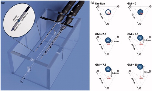
Figure 1. (a) A target device which ensured a standardised positioning of the applicators (‘A’) to the vessel (glass tube, ‘G’), was used for comparability of the experiments. It assisted in cutting the ablations exactly at the largest cross-sectional areas. Two electrodes are situated on each applicator, therefore six electrodes are used simultaneously in this multipolar configuration. (b) Five different applicator-to-vessel geometries (GM =0, 2.5, 5.0, 7.5 and 10) were tested. The coagulation zones were compared to a ‘dry run’ without saline perfusion but with a centrally placed vessel.
A multipolar RFA system (CelonLabPOWER, Olympus Surgical Technologies Europe, Hamburg, Germany) was used. Starting power was set to 60 J/s (W), according to the manufacturer’s recommendations (Celon AG Medicals Instruments, Version 3.0, based on Frericks et al. [Citation16]). A preinstalled resistance-controlled automatic power mode (RCAP) regulated the energy output. Three needle-like, bipolar applicators (CelonProSurge T-20, Olympus Surgical Technologies Europe) with an active length of 20 mm, a diameter of 1.8 mm and a closed internal cooling system were used (). A preinstalled ablation algorithm automatically activated two of the six electrodes at one time, while each pair of electrodes was alternately activated for 2 s. The algorithm started again from the beginning after all 15 pairs of electrodes had been activated once. Ablations were manually stopped after an energy input of 40.0 kJ. Three roller pumps (CelonAquaflowIII, Olympus Surgical Technologies Europe) ensured an internal cooling of the applicators with saline solution and a flow rate of 30 mL/min.
Three bipolar RF applicators were placed in parallel at a distance of 20 mm from each other (). A glass tube (hereafter referred to as ‘vessel‘) was used to simulate a natural liver vessel (inner/outer diameter: 3.4/5.0 mm). A roller pump perfused the artificial vessel using saline solution at room temperature and a flow rate of 100 mL/min to simulate natural blood perfusion. The vessel was placed parallel to the applicators along a bisecting line between two of the three applicators starting from the ablation centre. Five different applicator vessel geometries were tested ():
Vessel in the applicators’ geometrical centre (GM = 0)
Vessel 2.5 mm from the centre (GM = 2.5)
Vessel 5.0 mm from the centre (GM = 5.0)
Vessel 7.5 mm from the centre (GM = 7.5)
Vessel 10.0 mm from the centre (GM = 10)
A setting with a centrally placed and liquid-filled vessel but without perfusion was used as a ‘dry run’ to compare cooling effects. The dry run served as a control case: the setting was identical to the test runs, but the vessel was not perfused. Therefore, no perfusion-related energy withdrawal occurred. This allowed us to analyse the effect of vessel perfusion in comparison to the test runs.
Experiments were performed at room temperature. Six ablations were performed for each test series. A target device (acrylic glass, ) ensured an exact positioning of the three applicators to the vessel. Additionally it assisted in cutting the liver specimen exactly through the ablation centre.
Planimetry and analysis
Ablations were cut orthogonally to the applicators at the ablation centre. These cross sections were photographed next to a millimetre scale for a subsequent digital calibration. A thin-spline landmark registration was performed on the basis of the known applicator distance of 20 mm to avoid artefacts due to cutting deformations of the soft liver tissue [Citation19,Citation20]. Ablation borders were manually marked along the so-called ‘white zone’, a pale grey area in the centre of the ablation. The white zone was defined as an area of complete tissue necrosis [Citation21].
The coagulation zone masks of the dry run were averaged to an ‘idealised coagulation zone’ as the basis for further analysis of the cooling effect (). In detail, the coagulation zone masks of the dry run (n = 6) were subdivided into six equiangular (60°) sectors originating from the ablation centre point and merged on each other along the congruent edges. The outer faces of these 36 sectors were geometrically averaged to a single sector. Six of these identical sectors were assembled into the ‘idealised coagulation zone’ (three sectors were mirrored in order to compensate for asymmetries). The idealised coagulation zone served as a comparison group for the ablations with a perfused glass tube. Therefore, energy withdrawal by the vessel perfusion, which is responsible for cooling effects, was analysed in this study.
Figure 2. (a) The idealised coagulation zone (4) was averaged out of the six dry runs, which were divided into six equiangular sectors with the vessel as the centre point (1). These sectors were merged with each other along the congruent edges (2). The outer faces were geometrically averaged to a single sector (3), which was fanned out to the idealised coagulation zone (4). (b) An annular segmentation method with the vessel as the centre point was used in order to compare the idealised coagulation zone with the ablations with vascular perfusion. Three areas could be distinguished: (1) intersecting areas between idealised coagulation zone and ablation area, (2) where the idealised ablation area exceeded the ablation area (cooling effects), and (3) where the ablation area exceeded the idealised coagulation zone.
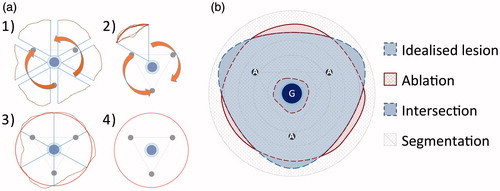
Masks of the coagulation zone from experiments with perfusion were compared to the idealised coagulation zone with a custom-made analysis software developed by Fraunhofer MEVIS [Citation19]. Differences in total coagulation zone area were measured. Additionally, a segmentation model was implemented to describe the vascular cooling effect in the vicinity of the vessel with higher precision (). Vascular cooling effects were defined as not ablated areas in test series with perfusion in comparison to the dry run without perfusion. An annular segmentation method with the vessel as centre point was chosen, since the vascular cooling effect emerged from the vessel. The ablated area between the coagulation zone masks and the idealised coagulation zone were compared; differences between these areas are expressed as percentages. Three different geometries could be distinguished:
Intersecting areas: coagulation zone mask and idealised coagulation zone were congruent, therefore no cooling effect or increase of ablation area could be observed.
Idealised coagulation zone exceeded the coagulation zone mask: cooling effect existed.
Coagulation zone mask exceeded the idealised coagulation zone: increase of ablation area, the ablation size of a perfused ablation was larger than the dry run.
Two types of analyses were used:
Coagulation zones were divided into a 5-mm annular segment situated around the vessel and a second segment between the first segment and the ablation border. This method was used to analyse the vascular cooling effect directly around the vessel.
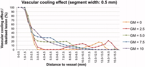
Coagulation zones were divided into equal annular segments of 0.5 mm width between the vessel and the ablation border. This analysis was used to outline the vascular cooling effect throughout the whole coagulation zone precisely.
Statistical analysis
Analyses were conducted with statistics software (SPSS version 20, IBM, Armonk, NY, USA). Data are expressed as mean value (minimum–maximum). The Kruskal–Wallis test was used for comparisons between more than two independent groups, the Mann–Whitney U test was used for two independent groups. The level of significance was 0.05 (two sided) for each statistical testing.
Results
Qualitative analysis
Thirty-six multipolar RFA were performed in total, corresponding to six ablations per test series. shows cross-sectional areas exemplarily for each test series. Typical ablation zones could be identified in all experiments. A dark brown area of carbonised tissue could be observed directly around the applicators, which corresponded to the ‘dehydration zone’. A pale grey area appeared next to the dehydration zone, which corresponded to the ‘white zone’. The white zone merged into a light red zone of ablated tissue (‘red zone’), which was followed by native liver tissue.
Round and homogenous ablation areas were seen in the test series without perfusion (dry run). The dehydration zone directly reached the vessel in these ablations, whereas a fringe of light red liver tissue could be observed around the vessel in ablations with perfusion. This area of non-ablated tissue correlated to a perivascular cooling effect.
The applicator-to-vessel geometry had a strong influence on the shape of the ablation zone (). While coagulation zones with a centrally placed vessel appeared annular (GM = 0, GM = 2.5), coagulation zones with an eccentrically placed vessel had a C-shaped ablation area (GM = 5.0, GM = 7.5, GM = 10) opening towards the vessel. A larger ablation size in comparison to the idealised coagulation zone area could be observed for these ablations at the vessel’s far side.
Quantitative analysis
shows the mean ablation areas of all test series. The idealised coagulation zone area, which was the average of the coagulation zone masks of the dry run, was 958 mm2. The idealised coagulation zone was used as a reference value for a prototypical coagulation zone without perfusion, defining vascular cooling effects or increase of ablation area for the current ablation. The mean ablation area of the test series with perfusion ranged between 859 mm2 (GM = 0) and 1072 mm2 (GM = 10). Significant differences in the size of the ablation area were observed between GM = 0/GM = 2.5 and GM = 10 (p < 0.05). However, no difference in the ablation area could be measured between the test series with perfusion and the idealised coagulation zone (p > 0.05).
Table 1. Cross sectional areas for all test series. ‘Increase of area’ and ‘cooling effect’ were based on the comparison with the idealised coagulation zone area (958 mm2). The ablation time for the idealised coagulation zone was 25:44 (24:32–28:01).
A cooling effect was observed in all test series (109–149 mm2). However, this was not significant when the entire ablation area was analysed. An increase in ablation size in comparison to the idealised coagulation zone could be observed between centrally placed vessels (GM = 0/GM = 2.5) and eccentrically placed vessels (GM = 7.5/GM = 10, p < 0.05).
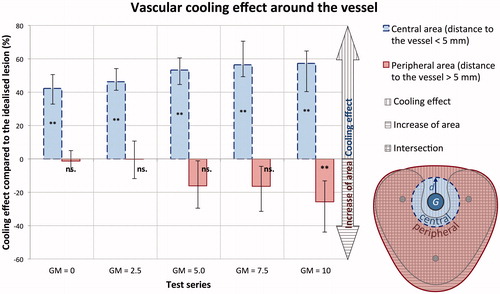
The vascular cooling effect around the vessel was additionally assessed by a two-segment annular segmentation model (). A vascular cooling effect could be observed adjacent to the vessels independent of the applicator-to-vessel geometry (p < 0.05). An increase of ablation area was measured in the outer segment for the most eccentrically placed applicator vessel geometry (GM = 10, p < 0.05). No difference in ablation area occurred in the outer segment for the remaining applicator vessel geometries (GM = 0–7.5, p > 0.05). Hence, a vascular cooling effect is to be expected in multipolar RFA independent of the applicator positioning in relation to a hepatic vessel ex vivo.
Figure 3. (a) Exemplary cross sectional areas for each test series (A: applicator, G: vessel). (b) Averaged masks of all test series: The idealised coagulation zone (vertically hatched) was situated behind the actual coagulation zone masks, whereas the actual coagulation zone mask was horizontally shaded and the intersecting area between both coagulation zones was crosswise hatched. The dry run showed a round and homogenous ablation area, which reached the vessel (G) directly, whereas all other test series with perfusion showed a cooling effect around the vessel. The coagulation zone appears annular (GM = 0, GM = 2.5) respectively c-shaped (GM = 5.0, GM = 7.5, GM = 10.0) in dependence of the applicator-to-vessel geometry.
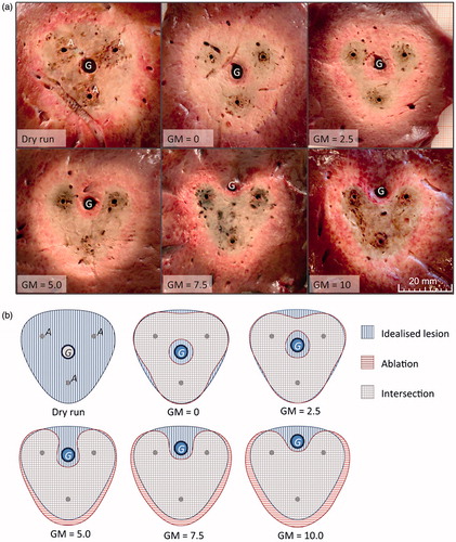
Figure 4. A similar cooling effect (fringe of native liver tissue surrounding the vessel) could be seen in all test series within a distance of 5 mm to the vessel (GM =0: 42%, GM =10: 57%) independent of the applicator-to-vessel geometry. A growth in coagulation zone area compared to the idealised coagulation zone is plotted negatively in the chart. Only for the most eccentrically placed vessel (GM =10) a significant (**) growth in coagulation zone area (25%) could be observed compared to the idealised coagulation zone. (p < 0.05; error bar: min–max; G = vessel; d = 5 mm).
A second analysis with 0.5-mm segments around the vessel was performed to outline the vascular cooling effect throughout the whole coagulation zone precisely (). A comparable cooling effect occurred in all test series up to a distance of 2.5 mm from the vessel. However, the plots between the test series diverged for distances greater than 2.5 mm from the vessel. While the cooling effects for eccentrically placed vessels (GM = 5.0, GM = 7.5 and GM = 10.0) gradually vanished with increasing distance to the vessel, the cooling effects for centrally placed vessels (GM = 0, GM = 2.5) disappeared quickly. However, the graph, indicating the cooling effect peaked again at the coagulation zone borders (). These observations most likely correlated with the macroscopic findings of the ablation areas. Annular ablation areas could be seen for centrally placed vessels with a small fringe of native tissue at the coagulation zone border, corresponding to the second peak in the diagram. C-shaped ablation areas were observed for more eccentrically placed vessels, showing a steadily decreasing cooling effect as a function of the distance from the vessel. Therefore, a constant cooling effect has to be expected around all vessels independent of applicator-to-vessel geometry ex vivo. However, the applicator-to-vessel geometry, and respectively the cooling effect, had a distinctive impact on coagulation zone shape.
Figure 5. Vascular cooling effect in comparison to the idealised coagulation zone. A similar cooling effect was observed for all five test series up to a distance of 2.5 mm from the vessel. Differences between the test series were observed beginning from a distance of 2.5 mm to the vessel. This effect was most likely to be explained by the macroscopic findings of the coagulation zones. Test series with centrally placed vessels (GM = 0, GM = 2.5) showed an annular shape with a small fringe of native tissue (cooling effect) at the coagulation zone borders. Whereas test series with eccentrically placed vessels (GM = 5.0, GM = 7.5 and GM = 10) occurred as c-shaped, resulting in a slowly decreasing cooling effect depending on the distance from the vessel.
Discussion
Vascular cooling effects during radiofrequency ablation (RFA) represent a well-known challenge in the treatment of malignant liver tumours adjacent to major hepatic vessels. RFA of tumours in the vicinity of major hepatic vessels is associated with an increased risk of local tumour recurrence. The vascular cooling effect has extensively been discussed for mono- and bipolar RFA in several ex vivo and in vivo studies [Citation10,Citation13,Citation22–24]. Multipolar RFA, using more than two electrodes simultaneously, has been introduced in recent years to obtain larger ablation volumes [Citation14–18]. Local energy density is higher in multipolar RFA compared to monopolar and bipolar RFA systems [Citation14]. Consequently, it appears likely that the vascular cooling effect of hepatic vessels is less distinctive in multipolar RFA. First clinical studies revealed promising results [Citation25,Citation26]. However, no systematic evaluation of the vascular cooling effect in multipolar RFA has been carried out so far. The objective of the actual study was to examine the vascular cooling effect in multipolar RFA in a standardised ex vivo model.
A vascular cooling effect occurred in all multipolar RFA ex vivo. The applicator-to-vessel geometry did not influence the size of the vascular cooling effect. However, the applicator-to-vessel position had a distinctive impact on the ablation shape. We used a multipolar RFA system with three internally cooled applicators. Some discrepancies could be found between the pre-calculated and the actual ablation times. Starting power was set to 60 W, while ablations were stopped after an energy input of 40 kJ. Therefore, the estimated ablation time was about 11 min. The difference of more than 14 min between calculated and real (median: 25 min 44 s) ablation time is explained by the ‘resistance controlled automatic power mode’ (RCAP mode) of the RF generator. Tissue resistance is automatically measured during ablation procedure in between the electrodes. The RF generator determines the actual power output depending on tissue resistance in order to avoid dehydration and therefore electrical isolation of the liver tissue. Median power output in the actual study was 25.9 W.
A straight glass tube (vessel) was used to simulate a natural hepatic vessel. Therefore, no unpredictable turbulences within the vessel, which additionally may influence the vascular cooling effect [Citation27], were expected in this standardised experimental setting. Continuous ablation areas resulted in all experiments. While the vascular perfusion did not have any significant influence on the total size of the ablation area, a localised vascular cooling effect could always be observed. This effect was independent of the applicator-to-vessel geometry. Encircling the vessel with the three applicators could not reduce the vascular cooling effect. Moreover, the size of the vascular cooling effect was similar for all applicator-to-vessel geometries within 2.5 mm around the vessel. Thus, the positioning of the applicators did not influence the cooling effect directly around the vessel. However, the applicator-to-vessel geometry affected the shape of the cooling effect, which in turn influenced the shape of the ablation area itself.
Our findings are in contrast to initial clinical studies, which reported low recurrence rates in multipolar RFA next to major hepatic vessels [Citation25,Citation26]. However, these studies included only a small patient collective (n < 46). No histological examinations could be performed to verify complete tumour ablation, particularly not adjacent to major hepatic vessels. Therefore, further in vivo experiments are obligatory examining the vascular cooling effects in multipolar RFA.
Limitations of the current study include the absence of natural liver perfusion and the lack of a tumour model. The experiments were intentionally performed without natural vascular liver perfusion. By doing so, an additional unpredictable direct cooling effect of adjacent hepatic vessels was avoided. In addition, a diffuse cooling effect caused by the capillary liver perfusion did not occur. Ablations in the clinical setting will be smaller due to the diffuse cooling effect [Citation13,Citation28–30]. However, while this effect leads to smaller RFA coagulation zones in general, it does not influence the ablation shape [Citation31]. Native porcine liver was used ex vivo in this study, due to the lack of an adequate tumour model. Porcine liver models are regularly used in local ablative research, since porcine liver has similar physiological and anatomical characteristics compared to human species [Citation32]. Ablations were performed in fresh liver within 6 h post-mortem to avoid artefacts by natural cell death [Citation13]. Elementary electrophysiological properties of porcine and human liver are well known [Citation33]. Therefore mathematical conversion of the test results into an in vivo model is possible [Citation34].
Another limitation could be seen in the glass tubes, which were used for the standardised simulation of natural liver vessels. However, it could be shown in previous studies that glass tubes have no influence on mono- and bipolar RFA [Citation13,Citation24]. We observed an increase in coagulation zone size on the opposite side of eccentrically placed vessels. This effect can be explained by a smoother energy distribution within the tissue: the vascular cooling effect acts in a similar way to the internal cooling system of the RF applicators and diminishes tissue carbonisation. This leads to a higher electrical conductivity, which in turn leads to a larger ablation [Citation12]. Another cause of the increase in coagulation zone size could be seen in a direct influence of the glass tube on the electrical field. In monopolar and bipolar RFA the glass tube does not influence the electrical field if the glass tube is situated at least 10 mm away from the electrode(s) [Citation13,Citation24]. However, the glass tube’s insulation may affect the electrical current in multipolar RFA if the glass tube is situated in between two electrodes. This assumption is supported by the findings in our study that the ablation zone increases, when the vessel is placed outside of the ablation centre. However, no cooling effect was observed in experiments with the glass tube but without perfusion (dry run). Therefore, the insulating effect of the glass tube was negotiable in this study.
Assuming that our results are confirmed in in vivo studies, the current study could have an essential impact on RFA therapy planning. Temporary blood flow occlusion seems to be reasonable for ablations where a major hepatic vessel is running through the tumour or is directly situated besides the tumour. In addition, hepatic vessels also influence the shape of the ablation, even if they do not have direct contact with the tumour. Therefore, the vascular cooling effect should also be taken into account if the vessel is adjacent to but not in direct contact with the tumour. In such cases it seems to be reasonable to place the applicators slightly away from the tumour towards the hepatic vessel to ensure complete tumour ablation. These considerations may appear somewhat theoretical, since a tumour is rarely situated adjacent to a single hepatic vessel. However, vascular cooling effects are quite complex [Citation34,Citation35]. Therefore, simplification seems to be crucial for the understanding of cooling effects. Moreover, the knowledge of the biophysical basics of cooling effects in RFA builds the basis for the development of numerical simulations for therapy planning [Citation34,Citation36,37].
Conclusions
Vascular cooling effects always occur adjacent to artificial liver vessels in multipolar RFA ex vivo. The applicator-to-vessel geometry has no influence on the size of the vascular cooling effect. However, the distance of the applicator to the vessel has a distinctive impact on the shape of the ablation area. Minor changes in applicator position can lead to incomplete tumour ablation, which is likely to cause tumour recurrence in the clinical situation. In vivo studies will be necessary to confirm these results. A temporary surgical blood flow occlusion, e.g. by a Pringle manoeuvre, seems to be advisable for the safe use of multipolar RFA next to major hepatic vessels until further studies are performed.
Disclosure statement
This study was supported by a grant from the “Deutsche Forschungsgemeinschaft” (Ref.-No. RI1131/3-3). The authors have no disclosures to make of any financial or personal relationships with other people or organisations that could inappropriately influence (bias) their work. The authors alone are responsible for the content and writing of the paper.
References
- Torre LA, Bray F, Siegel RL, Ferlay J, Lortet-Tieulent J, Jemal A. Global cancer statistics, 2012. CA Cancer J Clin 2015;65:87–108.
- Matias M, Casa-Nova M, Faria M, Pires R, Tato-Costa J, Ribeiro L, Costa L. Prognostic factors after liver resection for colorectal liver metastasis. Acta Médica Port 2015;28:357–69.
- Manfredi S, Lepage C, Hatem C, Coatmeur O, Faivre J, Bouvier AM. Epidemiology and management of liver metastases from colorectal cancer. Ann Surg 2006;244:254–9.
- Nicholl MB, Bilchik AJ. Thermal ablation of hepatic malignancy: useful but still not optimal. Eur J Surg Oncol 2008;34:318–23.
- Tanis E, Spliethoff JW, Evers DJ, Langhout GC, Snaebjornsson P, Prevoo W, et al. Real-time in vivo assessment of radiofrequency ablation of human colorectal liver metastases using diffuse reflectance spectroscopy. Eur J Surg Oncol 2016;42:251–9.
- Phan K, An VVG, Ha H, Phan S, Lam V, Pleass H. Hepatic resection for malignant liver tumours in the elderly: a systematic review and meta-analysis. ANZ J Surg 2015;85:815–22.
- Chan AC, Chan SC, Chok KS, Cheung TT, Chiu DW, Poon RT, et al. Treatment strategy for recurrent hepatocellular carcinoma: Salvage transplantation, repeated resection or radiofrequency ablation? Liver Transplant 2013;19:411–19.
- Liu P-H, Hsu C-Y, Lee Y-H, Hsia CY, Huang YH, Su CW, et al. When to perform surgical resection or radiofrequency ablation for early hepatocellular carcinoma? A nomogram-guided treatment strategy. Medicine (Baltimore) 2015;94:e1808.
- Cai H, Kong W, Zhou T, Qiu Y. Radiofrequency ablation versus reresection in treating recurrent hepatocellular carcinoma: a meta-analysis. Medicine (Baltimore) 2014;93:e122.
- Mulier S, Ni Y, Jamart J, Ruers T, Marchal G, Michel L. Local recurrence after hepatic radiofrequency coagulation: multivariate meta-analysis and review of contributing factors. Ann Surg 2005;242:158–171.
- Pillai K, Akhter J, Chua TC, Shehata M, Alzahrani N, Al-Alem I, et al. Heat sink effect on tumor ablation characteristics as observed in monopolar radiofrequency, bipolar radiofrequency, and microwave, using ex vivo calf liver model. Medicine (Baltimore) 2015;94:e580.
- Goldberg SN, Gazelle GS. Radiofrequency tissue ablation: physical principles and techniques for increasing coagulation necrosis. Hepatogastroenterology 2001;48:359–67.
- Lehmann KS, Ritz JP, Valdeig S, Knappe V, Schenk A, Weihusen A, et al. Ex situ quantification of the cooling effect of liver vessels on radiofrequency ablation. Langenbecks Arch Surg 2009;394:475–81.
- Haemmerich D, Tungjitkusolmun S, Staelin ST, Lee FT Jr, Mahvi DM, Webster JG. Finite-element analysis of hepatic multiple probe radio-frequency ablation. IEEE Trans Biomed Eng 2001;49:836–42.
- Haemmerich D, Lee FT Jr, Schutt DJ, Sampson LA, Webster JG, Fine JP, Mahvi DM. Large-volume radiofrequency ablation of ex vivo bovine liver with multiple cooled cluster electrodes. Radiology 2005;234:563–8.
- Frericks BB, Ritz JP, Roggan A, Wolf KJ, Albrecht T. Multipolar radiofrequency ablation of hepatic tumors: initial experience. Radiology2005;237:1056–62.
- Terraz S, Constantin C, Majno PE, Spahr L, Mentha G, Becker CD. Image-guided multipolar radiofrequency ablation of liver tumours: initial clinical results. Eur Radiol 2007;17:2253–61.
- Tacke J, Mahnken A, Roggan A, Günther RW. Multipolar radiofrequency ablation: first clinical results. RöFo 2004;176:324–9.
- Rieder C, Poch F, Tiesler H, Lehmann K, Preusser T. Software tool for the analysis of the coagulation zone from multipolare radiofrequency ablation. Paper presented at the Computer- und Roboterassistierte Chirurgie conference, Düsseldorf, 2012.
- Rohr K, Stiehl HS, Sprengel R, Buzug TM, Weese J, Kuhn M. Landmark-based elastic registration using approximating thin-plate splines. IEEE Trans Med Imaging 2001;20:526–34.
- Ng KK, Lam CM, Poon RT, Ai V, Tso WK, Fan ST. Porcine liver: morphologic characteristics and cell viability at experimental radiofrequency ablation with internally cooled electrodes. Radiology 2005;235:478–86.
- Huang H-W. Influence of blood vessel on the thermal lesion formation during radiofrequency ablation for liver tumors. Med Phys 2013;40:073303.
- Jiang K, Chen J, Liu Y, Liu J, Liu A, Dong J, Huang Z. ‘Heat-irrigate effect’ of radiofrequency ablation on relevant regional hepatocyte in living swine liver-initial study on pathology. Cell Biochem Biophys 2015;72:37–41.
- Welp C, Siebers S, Ermert H, Werner J. Investigation of the influence of blood flow rate on large vessel cooling in hepatic radiofrequency ablation. Biomed Tech (Berl) 2006;51:337–46.
- Bertrand J, Caillol F, Borentain P, Raoul JL, Heyries L, Bories E, et al. Percutaneous hepatic radiofrequency for hepatocellular carcinoma: results and outcome of 46 patients. Hepatic Med Evid Res 2015;7:21–7.
- Snoeren N, Nijkamp MW, Berendsen T, Govaert TH, van Kessel CS, Rinkes IHB, van Hillegersberg R. Multipolar radiofrequency ablation for colorectal liver metastases close to major hepatic vessels. Surgeon 2015;13:77–82.
- Liu YJ, Qiao AK, Nan Q, Yang XY. Thermal characteristics of microwave ablation in the vicinity of an arterial bifurcation. Int J Hyperth Off J Eur Soc Hyperthermic Oncol North Am Hyperth Group 2006;22:491–506.
- Clasen S, Schmidt D, Boss A, Dietz K, Kröber SM, Claussen CD, et al. Multipolar radiofrequency ablation with internally cooled electrodes: experimental study in ex vivo bovine liver with mathematic modeling. Radiology 2006;238:881–90.
- Frericks BB, Ritz JP, Albrecht T, Valdeig S, Schenk A, Wolf KJ, et al. Influence of intrahepatic vessels on volume and shape of percutaneous thermal ablation zones: in vivo evaluation in a porcine model. Invest Radiol 2008;43:211–18.
- Goldberg SN, Hahn PF, Tanabe KK, Mueller PR, Schima W, Athanasoulis CA, et al. Percutaneous radiofrequency tissue ablation: does perfusion-mediated tissue cooling limit coagulation necrosis? J Vasc Interv Radiol 1998;9:101–11.
- Mulier S, Ni Y, Miao Y, Rosière A, Khoury A, Marchal G, et al. Size and geometry of hepatic radiofrequency lesions. Eur J Surg Oncol 2003;29:867–78.
- Hiebl B, Müller C, Hünigen H, Gemeinhardt O, Plendl J, Jung F, et al. Gross anatomical variants of the vasculature of the GöttingenTM minipig. Appl Cardiopulm Pathophysiol 2010;14:236–43.
- Zurbuchen U, Holmer C, Lehmann KS, Stein T, Roggan A, Seifarth C, et al. Determination of the temperature-dependent electric conductivity of liver tissue ex vivo and in vivo: importance for therapy planning for the radiofrequency ablation of liver tumours. Int J Hyperthermia 2010;26:26–33.
- Berjano EJ. Theoretical modeling for radiofrequency ablation: state-of-the-art and challenges for the future. Biomed Eng Online 2006;524.
- Kröger T, Pätz T, Altrogge I, Schenk A, Lehmann KS, Frericks BB, et al. Fast estimation of the vascular cooling in RFA based on numerical simulation. Open Biomed Eng J 2010;4:16–26.
- Kröger T, Altrogge I, Preusser T, Pereira PL, Schmidt D, Weihusen A, et al. Numerical simulation of radio frequency ablation with state dependent material parameters in three space dimensions. Med Image Comput Comput-Assist Interv 2006;9:380–8.
- Rieder C, Kroeger T, Schumann C, Hahn HK. GPU-based real-time approximation of the ablation zone for radiofrequency ablation. IEEE Trans Vis Comput Graph 2011;17:1812–21.