
Abstract
The use of microwaves (MW) for thermal cancer treatment began in the late 1970s. At first, hyperthermia was induced by using single antennas applied interstitially. This was followed by arrays of multiple interstitial antennas driven synchronously at 915 or 2450 MHz. This early work focused on hyperthermia as an adjuvant therapy, but more recently has evolved into a thermally ablative monotherapy. Increased power required to thermally ablate tissues required additional developments such as internally cooled antennas. Larger tumours have also been ablated with MW antenna arrays activated synchronously or non-synchronously. Numerical modelling has provided clinical treatment planning guidance and device design insight throughout this history. MW thermal therapy systems, treatment planning, navigation and image guidance continue to evolve to provide better tools and options for clinicians and patients in order to provide targeting optimisation with the goal of improved treatment for the patient and durable cancer eradication. This paper reviews the history and related technological developments, including antenna design, of MW heating for both hyperthermia and ablation.
Introduction
Hyperthermia emerged in the 1970s as an alternative treatment option for cancerous lesions, to augment radiation and/or chemotherapy [Citation1–3]. Mild heating was induced by utilising radiofrequency (RF), microwave (MW), laser, therapeutic ultrasound (US) or purely conductive sources with a temperature target of 43 °C for 60 min [Citation4,Citation5]. In recent times, thermal ablation has become a more widespread treatment choice. Temperatures exceeding 50 °C are desired for tissue ablation, which can be used as a monotherapy in many patients, or with adjuvant therapies to augment the treatment effect. Several ablative interstitial energy sources have been described – laser, US, RF or MW – but at high powers MW ablation currently has several advantages: the highest rate of bulk tissue heating, performance that is relatively unaffected by tissue charring (severe desiccation and carbonisation) and the ability to create ablations that can cover most tumours up to 5 cm in diameter, plus the requisite tissue margin, in the shortest amount of time (typically 4–10 min) [Citation6]. Although modelling, navigation and treatment planning are introduced, they are more fully developed in other papers in this special issue.
Background on MW heating
Microwave energy propagation in tissue is radiative, and the absorption of that energy in tissue is primarily due to dielectric losses. The electromagnetic (EM) properties of tissue are governed by structural components including cellular membranes, proteins and water content [Citation7,Citation8]. MW antennas induce rotation of water molecules due to dipole action, causing them to oscillate at the frequency of the EM field (e.g. 915 and 2450 MHz are allowed for industrial, medical and scientific use in the United States and worldwide, respectively). Molecular motion is restricted though, by frictional forces that convert the rotational energy into heat. Thus, each atomic dipole becomes a heating source. Initially, when MW power is turned on, the polar molecules in tissue begin to rotate and heat immediately and simultaneously, with the greatest effect occurring within about 10 mm of the antenna depending on tissue type, applied frequency and power [Citation9]. This rapid heating results in coagulation necrosis of tissue when temperatures exceed about 55 °C (the same threshold as other ablative techniques such as laser, RF or US). The power distribution around a MW antenna together with heat conduction, including the influence of microscopic blood perfusion as well as thermally significant blood vessels [Citation10–12], determine the temperature and resulting treatment zone [Citation13]. As in other interstitial technologies used for ablation, MW sources are of comparable size (∼1.5–2.5 mm diameter), easily cooled (water or gas) and can be used singly or in arrays [Citation14–18], during open surgical, laparoscopic and percutaneous procedures [Citation19–21].
Mild thermal treatment: hyperthermia
Historical introduction to MW interstitial treatment
Invasive thermal therapy for cancer treatment was proposed in 1975 by Doss [Citation22] at the “First International Symposium on Cancer Therapy by Hyperthermia and Radiation”, in Washington, DC. Early work with MW antennas dates back to the late 1970s with activity by groups at Dartmouth College and the University of Maryland. Early papers from this era focus on dipole or monopole antenna designs, and include performance evaluation in animals and humans. Some of the earliest reports by Taylor [Citation23,Citation24] described the use of a “MW syringe” through which EM energy was “injected” into a target tumour. The technique had two unique features for its time: MW heating of deep biological structures via needle insertion and simultaneous chemotherapy. This was also the first study to suggest destruction by heat alone, a premonition of modern ablation. Similar work by Strohbehn et al. [Citation1] also demonstrated the potential of microwaves in the range of 500–1300 MHz at 3–10 W and suggested the possibility of treating with much higher temperatures. Further studies in a tumour model (mammary adenocarcinomas implanted in thighs of C3H mice) verified that a 1.0 GHz system could be employed in a living animal model to provide localised hyperthermia in deep-seated tumours [Citation2]. In humans, interstitial MW hyperthermia was found to effectively heat tumours, provide local control and significantly boost the effectiveness of both radiation therapy and chemotherapy in randomised trials [Citation14,Citation25–32]. It is important to note that no improvement in response was observed if the hyperthermia temperature goal of 42.5 °C for 45–60 min was not reached [Citation33].
Development of MW antennas for thermal therapy
One goal of the early animal and clinical studies was to obtain uniform heating and consistent temperatures within a tumour to enhance the effectiveness of radiation therapy. To do this required a variety of antenna designs (as shown in ) that had a range of power deposition patterns and when used singly or in arrays, could tailor the heating pattern for a particular tumour size and shape.
Figure 1. Ten early antenna designs suitable for 915 MHz [Citation9]. All antennas have a 3.5 cm junction to tip length. (A) Dipole with the tip section shorted to the inner conductor at the junction (1 mm gap); (B) 3.4 cm helix with a short at the antenna tip; (C) similar to (B) but turns wound counterclockwise; (D) similar to (B) but with a connection at the junction; (E) helical design with shorts at the junction and the tip; (F) similar to (D) but with a 23 mm junction gap; (G) similar to (D) but with two winding densities; (H) dipole design with 1.0 cm helix at the tip; (I) dipole with chokes over both proximal and distal sections; (J) similar to (H) but with a choke over the proximal section. See [Citation9] for specific absorption rate (SAR) comparison.
![Figure 1. Ten early antenna designs suitable for 915 MHz [Citation9]. All antennas have a 3.5 cm junction to tip length. (A) Dipole with the tip section shorted to the inner conductor at the junction (1 mm gap); (B) 3.4 cm helix with a short at the antenna tip; (C) similar to (B) but turns wound counterclockwise; (D) similar to (B) but with a connection at the junction; (E) helical design with shorts at the junction and the tip; (F) similar to (D) but with a 23 mm junction gap; (G) similar to (D) but with two winding densities; (H) dipole design with 1.0 cm helix at the tip; (I) dipole with chokes over both proximal and distal sections; (J) similar to (H) but with a choke over the proximal section. See [Citation9] for specific absorption rate (SAR) comparison.](/cms/asset/6ef6aecb-af85-4ff6-a346-724246a5160e/ihyt_a_1214884_f0001_b.jpg)
As an example, to accomplish tumour heating for hyperthermia, the system developed at Dartmouth [Citation9] incorporated the following features, all of which influenced the heating pattern during treatment to suitably match the tumour size and shape and increase the therapeutic percentage of the target [Citation14]:
choice of frequency: 433, 915 or 2450 MHz [Citation34];
choice of antennas to configure the heating patterns: dipole (λ/4 sections), choke dipole, helical, helical tip dipole;
fibre-optic thermometry with up to 24 channels for high spatial resolution, moving probes in catheters for continuous temperature mapping [Citation35];
sterile, sealed catheter housed the non-sterile antenna and one to three temperature probes;
pre-treatment planning for frequency choice and antenna spacing on a PC;
power control of each antenna based on temperature feedback and adjustable settings;
phase rotation to eradicate hot spots centrally;
catheter air cooling.
Clinical trials were set up by organ or target site: liver, kidney, pancreas, brain, inner ear, biliary tree, chest wall, breast, base of tongue, prostate, colorectal, and head and neck. More than 250 patients were treated between 1982 and 1993. The efforts to support these trials, concurrent with other major treatment centres worldwide, along with commercially available systems, helped establish the technical basis for MW therapy in the ensuing decades.
Use of numerical techniques
Electromagnetic field theory of the insulated dipole antenna was developed by King et al. [Citation36]. Subsequently, Trembly [Citation34] developed the theory of the linear, insulated antenna array embedded in an electrically dense medium for cancer therapy. This analytic development showed that although frequencies of 500–700 MHz deposited more energy centrally, the lengths of the antennas made them impractical for tumour treatment. Instead, 915 and 2450 MHz were more practical for clinical tumours. As computer simulation software and hardware improved, more precise and general models of MW therapy were developed. Simulations were used to incorporate design features that facilitated more controlled or broader heating patterns such as slots, high-dielectric materials, chokes and loading structures [Citation37–40]. In addition, bioheat transfer can be incorporated into the EM model to help predict and plan hyperthermia treatments from one or more antennas [Citation13,Citation41].
Evolution of MW antennas
The dipole antenna was the early workhorse for MW hyperthermia studies [Citation42]. The design consists of a coaxial line with an enlarged centre conductor protruding from its distal end (see ). Current alternates on the enlarged line and is mirrored by decaying currents on the outer coaxial conductor. The dipole provides excellent matching to the tissue load and a broad heating pattern, but is susceptible to performance changes with insertion depth [Citation43,Citation44]. Helical antennas () improved heating localisation over a range of insertion depths [Citation45–47]. Choke designs were also used to localise heating, to provide less dependence on insertion depth [Citation40]. Other variations and hybrids including modified dipoles, successfully combined the phase relationship of a dipole and the tip-heating of a helical antenna [Citation37]. Such antennas exhibited improved performance in arrays compared to helices. Several more designs have appeared and been reviewed [Citation48].
Cooling was added to MW hyperthermia antennas to preserve tissue in the vicinity of an antenna (e.g. urethra in prostate heating) or to cool the proximal antenna shaft at the skin insertion site [Citation49]. As a result, heating for up to 1.5 h was well-tolerated in animals [Citation50]. Cooling eventually allowed for longer-term therapy in human subjects as well. For example, sharp-tip and helical antennas with active cooling were used in the treatment of prostate cancer [Citation29]. Air cooling significantly improved the radial temperature uniformity for single antennas or arrays [Citation51], and increased the area heated by a factor of four [Citation52].
Clinical significance
Clinical trials have shown therapeutic MW use with hyperthermia over a range of anatomical sites: bone [Citation53], pancreas [Citation54], biliary tree [Citation28], rectum [Citation55], chest wall [Citation56], brain [Citation57,Citation58], bladder [Citation59] and prostate [Citation49]. Hyperthermia showed very good clinical promise when an adequate heat dose could be delivered. However, limitations to MW hyperthermia included frequent pain and discomfort, challenges with accurate thermal dosing due to antenna design and power limitations, challenging requirements for antenna placement into the target location, maximum heating limits in a therapeutic field (∼45 °C) in an awake patient, extraneous heating out of the target zone (normal tissue limitations), blood perfusion, and vascular heat sinks, and heterogeneous EM and thermal properties in and around the tumour. Thus, while the early MW hyperthermia era yielded substantial technical innovation that contributes to ablation performance today, the technique of interstitial MW hyperthermia, with its technical challenges to achieve complete heating of the tumour targets has had less of a role in cancer treatment over time.
Antenna arrays
Due to rapid power dissipation from a single antenna, temperature gradients of 5–8 °C/mm were found experimentally in highly perfused tissues. For example, to achieve 42.5 °C at a radius of 7.5 mm, 62 °C was needed at the antenna source in canine brain [Citation3]. Thus, as MW interstitial techniques evolved and larger tumours were treated, an array of antennas was necessary to avoid such intense heating [Citation57]. In most cases the antennas were delivered through up to 20 catheters (depending on the tumour size and morphology) that were also used for brachytherapy seed placement. The symmetrical dipole offered certain advantages in these arrays, as constructive interference created a specific absorption rate (SAR) value that was greatest in the centre of the array volume, not at the antennas [Citation34]. Arrays further allowed for temperature conformability with irregular tumour volumes as well as tumours deep within the body, providing flexibility in placement and number implanted [Citation44].
Synchronous arrays
Antennas which are in-phase (synchronous) are very useful for MW treatment of large or conformable volumes. Synchronous antennas (see below), although spaced apart, fill in the interior due to constructive interference [Citation60,Citation61]. Once the phase relationship is established in an array, the phase may then be steered to control the power deposition pattern or SAR and subsequent temperature distribution [Citation60]. Additionally, heating volume was increased with changing phase among antennas and phase shifting was able to shift heating out to the periphery of a tumour [Citation41,Citation62].
In the non-synchronous case, the antennas have no phase relationship or central constructive interference, as if the antennas were turned on rapidly at separate times. As a result, there is little central power deposition and the 25 and 50% isoSAR contours are only found in the vicinity of the antennas. Contrast these results to the synchronous case which shows a large central region of 25 and 50% isoSAR, with values approaching 75% isoSAR. This implies that in (right), the central region would heat immediately, whereas in (left), since less than 25% SAR is found centrally, it would rely on thermal conduction to fill in all zones not in the immediate vicinity of the antenna.
Figure 2. Power deposition patterns or specific absorption rate (SAR) of Non-synchronous vs. Synchronous antenna arrays. (Left) Simulations of three non-synchronous antennas (triangular configuration, into the page, 915 MHz, not in phase). Note that the highest SAR is in the neighbourhood around the antennas themselves. The central region between antennas is only at 20% SAR (antenna marked by arrow). (Right) Simulations of three synchronous antennas (triangular configuration, into the page, 915 MHz, in phase). Note that the central SAR is 70% SAR, much higher in this in-phase example due to constructive interference. Experimentally, three antennas with 2.5 cm spacing at 45 W/channel and 10 min resulted in a volume of 89.8 cm3 when operated synchronously, but only 53.4 cm3 non-synchronously [Citation3].
![Figure 2. Power deposition patterns or specific absorption rate (SAR) of Non-synchronous vs. Synchronous antenna arrays. (Left) Simulations of three non-synchronous antennas (triangular configuration, into the page, 915 MHz, not in phase). Note that the highest SAR is in the neighbourhood around the antennas themselves. The central region between antennas is only at 20% SAR (antenna marked by arrow). (Right) Simulations of three synchronous antennas (triangular configuration, into the page, 915 MHz, in phase). Note that the central SAR is 70% SAR, much higher in this in-phase example due to constructive interference. Experimentally, three antennas with 2.5 cm spacing at 45 W/channel and 10 min resulted in a volume of 89.8 cm3 when operated synchronously, but only 53.4 cm3 non-synchronously [Citation3].](/cms/asset/499fb7b4-7f1d-4cb1-ace0-2d3b850db423/ihyt_a_1214884_f0002_c.jpg)
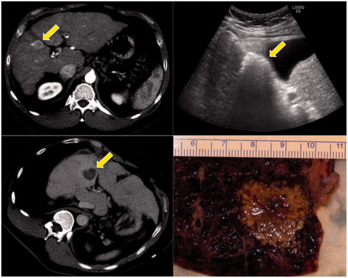
Figure 3. Clinical example of microwave ablation in a 57-year-old male with hepatocellular carcinoma and cirrhosis. The initial tumour was 2.6 cm on contrast computed tomography (CT) (upper left, see arrow). Intra-procedural ultrasound shows water vaporisation and bubbles highlight the zone of ablation (upper right). Post-ablation contrast CT shows the non-enhancing zone of ablation (lower left). This patient went on to transplant within a few days, and the post-ablation explant shows the ablated tumour plus a surrounding tissue margin (lower right).
High-temperature thermal treatment: ablation
Image-guided interventions using microwaves
Over the last decade there has been a renewed interest in MW energy sources for thermal therapy, but with the objective of high-temperature ablation rather than mild hyperthermia. MW ablation may be performed using multiple approaches, including open or laparoscopic surgery, as well as percutaneous puncture. The goal of ablation is to provide a zone of coagulation necrosis (at least 50 °C) that encompasses the tumour, plus a circumferential margin of normal tissue (at least 5 mm). Building on the potential benefits of MW energy for hyperthermia, MW ablation offers higher temperatures, larger ablation volumes, faster heating, greater ability to use multiple applicators, more efficient heating of cystic masses and less procedural pain compared to other ablation modalities such as RF, laser or US [Citation63,Citation64] (see ).
Table 1. In thermal therapy, transition from hyperthermia to thermal ablation.
The outcome of any thermal ablation procedure largely depends on the size and location of the target lesion. Historically, tumours larger than 3 cm pose a greater risk for recurrence. Local heat sinks such as large blood vessels can protect adjacent tumour tissue and lead to local recurrence. If a single ablation does not completely cover the target zone, several overlapping ablations may be performed serially or an array of antennas (e.g. 2, 3 or 4) is inserted and simultaneously powered for large ablations. Multi-channel systems may also treat several discrete tumours simultaneously. The following material will highlight how MW ablation systems have been designed to address these historical challenges.
Beyond MW hyperthermia
In thermal ablation, tissue is necrosed after typical exposure times of seconds to minutes and peak temperatures exceeding 50–70 °C. For example, He and Bischof [Citation65] showed that human renal cells were 90% nonviable after 60 s at 60 °C, and nearly 100% nonviable at 70 °C with no hold time required. There is some variation in critical temperature among cell types though [Citation66]. Thus, the objective of MW ablation is to create the highest temperatures possible to ensure complete eradication of the tumour. At these temperatures, effects that were not considered in MW hyperthermia must now be considered, most notably tissue desiccation and water vaporisation [Citation67,Citation68]. In addition, considerable tissue shrinking can cause underestimation of the true ablation volume [Citation69,Citation70].
Ablation using MW energy has been studied often with the preceding technology of RF ablation as a reference. Schramm et al. [Citation71] separated the components that lead to heating in tissue and showed the contributions by (1) direct heating, (2) thermal conduction and (3) perfusion over a range of distances from the antenna or RF needle. Based on typical ablation parameters, their simulation data suggest that while thermal conduction was the dominant mode of heat transfer from 12–19 mm radius for RF, direct heating was dominant throughout the treatment zone with MW. This finding suggests that greater power input may lead to greater ablation zone size. Later experimental analysis confirmed the predominance of direct heating in MW ablations [Citation72].
Andreano et al. [Citation73] also showed that MW ablations tended to be larger than RF ablations for a given energy input, likely due to the broader heating profile as MW energy more effectively propagates through charred and desiccated tissue. This last point is one of the most important to consider for MW ablation compared to MW hyperthermia. During MW ablation, temperatures routinely exceed 100 °C, leading to substantial water vaporisation inside of the ablation zone. The vaporised water drastically alters the tissue dielectric properties and specific heat capacity, and increases heat transfer as it is pushed into the peripheral ablation zone by internal pressures and consequently releases latent heat [Citation67,Citation68]. Such effects were not a part of the hyperthermia regimen. Therefore, the main technical advancements for MW ablation have been to capitalise on greater power delivery and to provide improved control of the direct heating process.
Consequently, the practice of characterising MW ablation devices has been different than for hyperthermia. Since the interplay between EM and thermal effects is so pronounced, using phantoms and SAR to characterise device performance has given way to assessing the extent and pattern of ablation zones in tissue models. Subsequent clinical studies follow the patients and ablations over time to assess the ablation performance, success and tumour resolution, generally with imaging only.
Clinical MW ablation
Clinical trials have shown therapeutic MW ablation has been used over a range of anatomical sites: fibroids [Citation74], lung [Citation75], kidney [Citation76,Citation77], bone [Citation78,Citation79], pancreas [Citation80], chest wall [Citation81], adrenal glands [Citation82], liver [Citation83], spleen [Citation84], head and neck [Citation85], breast [Citation86] and prostate [Citation87]. A number of clinical MW ablation (which was termed “percutaneous microwave coagulation therapy” or PMCT) studies were performed in Japan [Citation88–90]. Those early efforts demonstrated the successful percutaneous ablation of small human tumours with thin, sharp-tip antennas. The studies also incorporated methods using 60 W of power during withdrawal, in order to coagulate the antenna insertion track to provide haemostasis and prevent tumour cell seeding of the exit track [Citation91]. However, the relatively short treatment times and issues with antenna shaft heating limited the ablations to ∼15–20 mm diameter and, therefore, limited the broader applicability of those first-generation ablation systems. The next generation of systems included FDA-cleared and CE-marked devices that included features such as active cooling to increase treatment time [Citation16,Citation18,Citation92]. Reviews of these systems touted faster treatments with greater volumes of tissue damage compared to earlier MW ablation systems, but also noted deficiencies such as elongated ablations and insufficient ablation size to cover a wide array of tumours [Citation93]. More recent studies with generators exceeding 100 W output power and antenna designs that provide limited ablation length have shown greater efficacy (), even for tumours exceeding 3 cm in diameter [Citation18,Citation94–96].
Antenna developments
Many of the same designs used for hyperthermia have been adopted for thermal ablation devices [Citation97]. However, when used as a single antenna (rather than an array), many of those devices create ablation zones that are more elongated than the tumours they are targeting. A number of length-limiting designs have been described, including miniaturised choke, loaded triaxial, dual slot, and antenna systems with adaptations for changing tissue properties [Citation98–102]. Such designs can help to increase the size and sphericity of the ablation zone to ensure that the treatment is specifically targeting the tumour and margin, while minimising non-targeted, normal tissue involvement. Some studies have also explored frequencies up to 14.5 GHz [Citation103,Citation104]. Other efforts have focused on antennas with asymmetric SAR [Citation105], and optimisations for non-solid organs such as the lung [Citation106]. These factors in antenna design are explored in another review article in this special issue.
Power delivery
The desire for larger ablation zones also fuelled the development of high-power generators. While hyperthermia equipment may have operated at up to 10 W per antenna, ablation systems are now designed to deliver over 100 W. Without cooling, the small coaxial cables that carry MW energy through the antenna feeding structure overheat and fail at these powers, and can create thermal damage outside of the target zone, as well as the potential for contact skin burns. Water cooling inside of the antenna can eliminate this effect () [Citation107]. Other systems have moved to cryogenic gases for cooling to reduce antenna diameter and thus its invasiveness [Citation17].
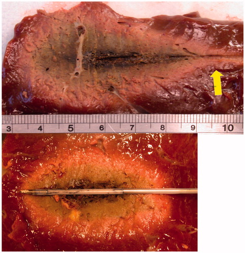
Figure 4. Microwave ablations created with 100 W for 10 min in ex vivo bovine liver. Ablations were created without the use of cooling (above) or with a prototype water-cooled antenna (below). Note the increased sphericity in the lower figure as the “tail” of the ablation (arrow) was eliminated with cooling.
With high-power MW, tracking has also been observed, where hot steam escapes down large vessels or ducts in the liver and creates alternate ablation sites [Citation10]. The Holy Grail for ablation has been achieving a spherical ablation, reproducibly. Hines-Peralta et al. [Citation108] emphasised a sphericity index, where a sphere =1. Many studies, either ex vivo or in vivo now utilise this metric for performance. In their study (see ), with a 5.6 mm diameter antenna, power and treatment duration were associated with coagulation diameter, in a sigmoidal fashion, with power levels of 50–150 W at 2450 MHz [Citation108]. Using an in vivo porcine model at 150 W and 8 min, a coagulation diameter of 5.7 cm was achieved. Another study performed in vivo (porcine) at shorter times (3 min) with basically the same antenna achieved ablations of 4 cm (at 150 W) and 5 cm (at 200 W) [Citation103]. In addition, coagulation diameters plateaued at about 8 min at each power level in vivo. Powers at 50, 100, 150 and 200 W resulted in ablation diameters of 3, 4, 5 and 6 cm, respectively. The study also found that the ablation volumes were more spherical in vivo than ex vivo, most likely due to the effects of perfusion in the highly vascular liver.
Figure 5. (Left) Ex vivo results of time and power vs. coagulation diameter. Plots show the coagulation diameter resulting in 50, 100 and 150 W delivered from 2 to 20 min. The diameter increases over time in this ex vivo porcine model. (Right) In vivo results of time and power vs. coagulation diameter in porcine model. Plots show the coagulation diameter resulting in 50, 100 and 150 W delivered from 2 to 20 min. The diameter increases over time until about 8 min when it plateaus in this in vivo model [Citation108].
![Figure 5. (Left) Ex vivo results of time and power vs. coagulation diameter. Plots show the coagulation diameter resulting in 50, 100 and 150 W delivered from 2 to 20 min. The diameter increases over time in this ex vivo porcine model. (Right) In vivo results of time and power vs. coagulation diameter in porcine model. Plots show the coagulation diameter resulting in 50, 100 and 150 W delivered from 2 to 20 min. The diameter increases over time until about 8 min when it plateaus in this in vivo model [Citation108].](/cms/asset/ccf3b868-ec70-48e6-a089-4445f40680f6/ihyt_a_1214884_f0005_c.jpg)
With flexibility in power output has come additional flexibility in power delivery. Bedoya et al. [Citation109] demonstrated the potential for using MW ablation in a pulsed power mode. In particular, they noted that pulsing a high instantaneous power can create ablation zones that are significantly larger than if the same energy were delivered using a low continuous power (e.g. 100 W at 25% duty compared to 25 W at 100% duty). A more pronounced difference between pulsed and continuous mode was noted at lower duty cycles. This concept can be extended to a multiple-antenna array based on switching as well [Citation110]. Additional research on the use of pulsed-mode MW ablation will help define how power is delivered in future systems.
MW arrays for ablation
Despite these advances in antenna design and increased power delivery, large tumours may require ablations that cannot be produced by a single antenna, with today’s technology. To create very large ablations (4–6 cm or larger in 4–10 min), and to avoid a large number of sequential ablations that singly add to a larger volume, antenna arrays of thin antennas are used [Citation111]. Multiple antennas in an array are required for most tumours with an irregular shape requiring antennas with custom spacing and trajectory. These antennas could be symmetrically placed or configured to match a patient’s tumour shape if it is irregular. As with hyperthermia, there are advantages with synchronous systems that have a constructive phase relationship among the antennas of the array. Heating at the centre of a synchronous array will increase as N2 (where N = number of antennas), assuming parallel antennas with tips in a plane [Citation15,Citation60]. However, even the use of non-synchronous arrays will increase ablation zone size through the thermal synergy between growing ablations [Citation112]. In addition, there may be physiological barriers (e.g. ribs or other bony structures) that prevent parallel antenna trajectories.
Advantages of MW ablation in clinical practice
Microwaves have been reported to have several advantages over other technologies (interstitial RF or laser) which directly relate to clinical treatments in humans: (1) deep energy penetration, which may increase as tissue desiccates [Citation108]; (2) no direct electrical contact required [thus all metallic surfaces may be coated with non-stick coatings]; (3) rapid heating and shorter procedures; (4) no power delivery limitations due to tissue charring; (5) higher temperatures to improve heat conduction; (6) vascular coagulation; (7) large ablation volumes; and (8) phase relationships between antennas (allowing constructive or destructive interference) [Citation113]. MW ablation has a proven clinical track record in providing an alternative to surgical resection, with reliable local control, and high rates of complete ablation [Citation114]. In addition, based on a meta-analysis, MW ablation appears to perform better in large tumours than RF ablation [Citation115].
Tissue model considerations
Based on the technologies described so far, there are now seven FDA-cleared MW ablation systems, with a number of other systems in clinical use worldwide. Manufacturers typically provide reference data in the Instructions for Use (IFU) from ex vivo, non-tumour studies regarding ablation sizes and shapes vs. time and power used. Winokur et al. [Citation116] found that these reference values for ablation size can be larger than the actual patient values based on immediate analysis of post-ablation contrast-enhanced computed tomography (CT). Moreover, other early predictors of clinical treatment outcomes have been evaluated in animal models and compared to human data. For example, in one study an applied power of 80 W for 25 min yielded an ablation 3.5 cm ×5.9 cm in normal porcine liver in vivo. The same power and time used in 90 primary and metastatic human tumours yielded an average ablation zone of 3.5 cm ×5.0 cm [Citation18]. Similar results (3–5 cm ablation zones) have been reported with other clinical treatment performance assessment [Citation95,Citation96,Citation117].
While many current MW ablation systems have the capability to address a wide range of tumour sizes, it is important to assess the performance difference among systems. A comparison of four MW systems in ex vivo bovine liver demonstrated considerable variance in the ablation outcome, with ablation volumes of 10.9–57.5 cm3 and single-antenna sphericity indices of 0.52–0.75 (with 1.0 being a perfect sphere) [Citation117]. As a cautionary note, the size and shape of the ex vivo tissue may affect the size and shape of the MW ablation [Citation118]. Another clinical system varies frequency (902–928 MHz) to manage reflected power and relies on an uncooled antenna with low power. Clinical studies show that when the system was used for 15–60 min at 10–32 W to treat 23 liver tumours of 4–7 cm in diameter, there was an average of 2.5 treatments needed per tumour [Citation119]. Furthermore, in another study with the same system, tumours larger than 3 cm were only partially ablated [Citation120]. Based on the heterogeneity in results among institutions, systems and study designs, along with the manufacturer’s ablation guidance only in ex vivo tissue, it is vitally important for any practitioner to understand their particular device and its optimal conditions for use, both by ex vivo and in vivo animal models, and in carefully followed clinical studies with imaging. The MW system is only one part of the treatment equation.
Discussion
Microwave ablation continues to evolve into the treatment paradigm for focal tumours in many anatomic locations. A number of treatment tools have been developed based on historical hyperthermia devices to facilitate more complete ablation procedures. Among these, the combination of actively cooled antennas and high-power MW generators has launched MW ablation into a dominant position. Other treatment utilities common in hyperthermia have not yet seen wide adoption for MW ablation: computer-aided treatment planning, navigation, greater feedback and control, and real-time imaging for monitoring. Although treatment planning could prescribe the skin entry and trajectory for each antenna, each antenna needs to be tracked to accurately show placement in the patient and then overlaid in patient space along with the tumour target location. If used synchronously in arrays, MW power steering may also aid in filling in the ablation as the treatment progresses.
In the future, the usage of ablation is predicted to address the following. (A) Larger targets: as raw generator power increases, combined with higher power antennas and more array channels, MW thermal ablation is expected to make further in-roads into larger ablations that will treat 7 cm tumours or larger [Citation121,Citation122]. (B) Specialised antennas: designed to selectively heat focal zones presently treated with RF applicators, but in less time and with greater precision [Citation100,Citation101,Citation123]. (C) Navigation with co-registration: technology exists to co-register a treatment target with a treatment device but has not been incorporated into systems that utilise ablation [Citation124,Citation125]. (D) New malignant organ sites: following liver ablation, new tumour sites will be targeted with MW, including more lung, breast, prostate and bone mets (see citations in Section 4.3). (E) New non-malignant organ sites: there are other non-cancerous sites favourable for MW ablation with custom applicators that will offer the patient an alternative to surgery, with sites including the prostate to treat benign prostatic hyperplasia [Citation126] as well as uterine fibroids [Citation75].
There is a tremendous amount of activity in planning, navigation and guidance, and assessment in the field of ablation. The “Treatment Room of the Future” may include CT, MR (magnetic resonance) and PET (positron emission tomography) in the treatment room, but there must be studies to show whether there are improved patient outcomes. Real-time feedback of temperature, thermal dose and coagulation boundaries, combined with treatment planning could improve outcomes, facilitate ablation and convert ablation into a more routine, iterative procedure, modelled after radiation oncology. Wood et al. [Citation127] discuss this setting up the treatment room of the future at NIH that includes the following: (1) pre-procedural: co-registered PET, MR and CT, tumour and vascular segmentation, vascular tree visualised in the treatment field, antenna pre-treatment planning with FEM model to predict performance; (2) intra-procedural: guidance and tracking of devices, tracked US, organ motion compensation, ablation feedback, thermography and thermal dose monitoring; and (3) post-procedural: functional MR/PET/CT, US-based elastography and match of pre- to post-ablation. Although that paper was published in 2007, more contemporary papers have begun to show the successful clinical implementation and technical hurdles overcome to implement image registration and fusion [Citation124,Citation128], treatment planning with on-the-fly computational modelling [Citation129,Citation130] and robotic assistance [Citation125,Citation129]. Beyond experimental work at academic medical centres, many of these features have yet to be clinically available by manufacturers, probably due to a combination of technology, safety, and regulatory hurdles.
Conclusions
This paper shows the transition and evolution from hyperthermia to ablation with interstitial techniques and sources. By examining the early history, it is clearly shown that direct MW antenna insertion into tissue, high-temperature heating, antenna cooling, synchronous and non-synchronous array operation, as well as treatment planning have been practised for 20–30 years. The ablation procedures now incorporate real-time image guidance but commonly lack the use of extensive treatment planning and temperature monitoring typical of historical hyperthermia treatments. Future systems are expected to incorporate advanced features in 3D that need to include: treatment planning, image-guided placement, system knowledge of actual antenna location and trajectory along with target localisation, real-time thermography or necrosis boundary imaging, as well as flexibility in antenna locations, and power deposition control, including directionality for conformability with the target. Better models are needed to predict coagulative volumes with MW which will fully utilise tissue dielectric and thermal properties (tumour vs. normal) as a function of temperature, as well as perfusion and water content changes. The ultimate question though, concerns patient outcomes: quality of life, tumour recurrence, and pain. Improvements should be expected in patient outcomes as a justification of the time spent, personnel required, and investment in new technology for thermal ablation treatment.
Disclosure statement
Thomas Ryan has no conflicts of interest. Chris Brace consults with Neuwave and Symple Surgery.
References
- Strohbehn JW, Bowers ED, Walsh JE, et al. (1979). An invasive microwave antenna for locally-induced hyperthermia for cancer therapy. J Microw Power 14:339–50.
- Douple EB, Srohbehn JW, Bowers ED, et al. (1979). Cancer therapy with localized hyperthermia using an invasive microwave system. J Microw Power 14:181–86.
- Ryan TP, Turner PF, Hamilton B. (2010). Interstitial microwave transition from hyperthermia to ablation: historical perspectives and current trends in thermal therapy. Int J Hyperthermia 26:415–33.
- Sapareto SA, Dewey WC. (1984). Thermal dose determination in cancer therapy. Int J Radiat Oncol Biol Phys 10:787–800.
- Hahn GM, Ning SC, Elizaga M, et al. (1989). A comparison of thermal responses of human and rodent cells. Int J Radiat Biol 56:817–25.
- Ahmed M, Brace CL, Lee FT Jr, et al. (2011). Principles of and advances in percutaneous ablation. Radiology 258:351–69.
- Schwan HP, Foster KR. (1977). Microwave dielectric properties of tissue. Some comments on the rotational mobility of tissue water. Biophys J 17:193–97.
- Stuchly MA. (1979). Interaction of radiofrequency and microwave radiation with living systems. A review of mechanisms. Radiat Environ Biophys 16:1–14.
- Trembly B, Ryan T, Strohbehn JW. (1991). Physics of microwave hyperthermia. In: Interstitial hyperthermia: physics, biology and clinical aspects. New York: VSP Press; p. 11–98.
- Garrean S, Hering J, Saied A, et al. (2009). Ultrasound monitoring of a novel microwave ablation (MWA) device in porcine liver: lessons learned and phenomena observed on ablative effects near major intrahepatic vessels. J Gastrointest Surg 13:334–40.
- Chiang J, Willey BJ, Del Rio AM, et al. (2014). Predictors of thrombosis in hepatic vasculature during microwave tumor ablation of an in vivo porcine model. J Vasc Interv Radiol 25:1965–71.
- Yu NC, Raman SS, Kim YJ, et al. (2008). Microwave liver ablation: influence of hepatic vein size on heat-sink effect in a porcine model. J Vasc Interv Radiol 19:1087–92.
- Pennes HH. (1948). Analysis of tissue and arterial blood temperatures in the resting human forearm. J Appl Physiol 1:93–122.
- Ryan TP, Trembly BS, Roberts DW, et al. (1994). Brain hyperthermia: I. Interstitial microwave antenna array techniques – the Dartmouth experience. Int J Radiat Oncol Biol Phys 29:1065–78.
- Brace CL, Laeseke PF, Sampson LA, et al. (2007). Microwave ablation with multiple simultaneously powered small-gauge triaxial antennas: results from an in vivo swine liver model. Radiology 244:151–56.
- Simon CJ, Dupuy DE, Iannitti DA, et al. (2006). Intraoperative triple antenna hepatic microwave ablation. AJR Am J Roentgenol 187:W333–W340.
- Knavel EM, Hinshaw JL, Lubner MG, et al. (2012). High-powered gas-cooled microwave ablation: shaft cooling creates an effective stick function without altering the ablation zone. AJR Am J Roentgenol 198:W260–W265.
- Kuang M, Lu MD, Xie XY, et al. (2007). Liver cancer: increased microwave delivery to ablation zone with cooled-shaft antenna – experimental and clinical studies. Radiology 242:914–24.
- Yokoyama T, Egami K, Miyamoto M, et al. (2003). Percutaneous and laparoscopic approaches of radiofrequency ablation treatment for liver cancer. J Hepatobiliary Pancreat Surg 10:425–27.
- Raut CP, Izzo F, Marra P, et al. (2005). Significant long-term survival after radiofrequency ablation of unresectable hepatocellular carcinoma in patients with cirrhosis. Ann Surg Oncol 12:616–28.
- Jagad RB, Koshariya M, Kawamoto J, et al. (2008). Laparoscopic microwave ablation of liver tumors: our experience. Hepatogastroenterology 55:27–32.
- Doss JD. (1975). Use of RF fields to produce hyperthermia in animal tumors. Proc Int Symp Cancer Ther Hyperthermia Radiat 226–27.
- Taylor LS. (1978). Electromagnetic syringe. IEEE Trans Biomed Eng 25:303–4.
- Taylor LS. (1980). Implantable radiators for cancer therapy by microwave hyperthermia. Proc IEEE 68:142–49.
- Sneed PK, Stauffer PR, McDermott MW, et al. (1998). Survival benefit of hyperthermia in a prospective randomized trial of brachytherapy boost +/- hyperthermia for glioblastoma multiforme. Int J Radiat Oncol Biol Phys 40:287–95.
- Sapozink MD, Boyd SD, Astrahan MA, et al. (1990). Transurethral hyperthermia for benign prostatic hyperplasia: preliminary clinical results. J Urol 143:944–9; discussion 949–50.
- Gross EJ, Cetas TC, Stauffer PR, et al. (1990). Experimental assessment of phased-array heating of neck tumours. Int J Hyperthermia 6:453–74.
- Coughlin CT, Douple EB, Strohbehn JW, et al. (1983). Interstitial hyperthermia in combination with brachytherapy. Radiology 148:285–88.
- Sherar MD, Trachtenberg J, Davidson SRH, et al. (2004). Interstitial microwave thermal therapy and its application to the treatment of recurrent prostate cancer. Int J Hyperthermia 20:757–68.
- Seegenschmiedt MH, Karlsson UL, Black P, et al. (1995). Thermoradiotherapy for brain tumors. Three cases of recurrent malignant astrocytoma and review of clinical experience. Am J Clin Oncol 18:510–18.
- Overgaard J, Gonzalez Gonzalez D, Hulshof MC, et al. (1995). Randomised trial of hyperthermia as adjuvant to radiotherapy for recurrent or metastatic malignant melanoma. European Society for Hyperthermic Oncology. Lancet 345:540–3.
- Jones EL, Oleson JR, Prosnitz LR, et al. (2005). Randomized trial of hyperthermia and radiation for superficial tumors. J Clin Oncol 23:3079–85.
- Emami B, Scott C, Perez CA, et al. (1996). Phase III study of interstitial thermoradiotherapy compared with interstitial radiotherapy alone in the treatment of recurrent or persistent human tumors. A prospectively controlled randomized study by the Radiation Therapy Group. Int J Radiat Oncol Biol Phys 34:1097–104.
- Trembly BS. (1985). The effects of driving frequency and antenna length on power deposition within a microwave antenna array used for hyperthermia. IEEE Trans Biomed Eng 32:152–7.
- Ryan TP, Wikoff RP, Hoopes PJ. (1991). Design of an automated temperature mapping system for ultrasound or microwave hyperthermia. J Biomed Eng 13:348–54.
- King RWP, Trembly BS, Strohbehn JW. (1983). The electromagnetic field of an insulated antenna in a conducting or dielectric medium. IEEE Trans Microw Theory Tech 31:574–83.
- Hamada L, Saito K, Yoshimura H, et al. (2000). Dielectric-loaded coaxial-slot antenna for interstitial microwave hyperthermia: longitudinal control of heating patterns. Int J Hyperthermia 16:219–29.
- Ito K, Hyodo M, Shimura M, et al. (1990). Thin applicator having coaxial ring slots for interstitial microwave hyperthermia. Ant Prop Soc Int Symp 3:1233–6.
- Pisa S, Cavagnaro M, Bernardi P, et al. (2001). A 915-MHz antenna for microwave thermal ablation treatment: physical design, computer modeling and experimental measurement. IEEE Trans Biomed Eng 48:599–601.
- Wong TZ, Trembly BS. (1994). A theoretical model for input impedance of interstitial microwave antennas with choke. Int J Radiat Oncol Biol Phys 28:673–82.
- Camart JC, Dubois L, Fabre JJ, et al. (1993). 915 MHz microwave interstitial hyperthermia. Part II: array of phase-monitored antennas. Int J Hyperthermia 9:445–54.
- Hurter W, Reinbold F, Lorenz W. (1991). A dipole antenna for interstitial microwave hyperthermia. IEEE Trans Microw Theory Tech 39:1048–54.
- James BJ, Strohbehn JW, Mechling JA, et al. (1989). The effect of insertion depth on the theoretical SAR patterns of 915 MHz dipole antenna arrays for hyperthermia. Int J Hyperthermia 5:733–47.
- Ryan TP, Mechling JA, Strohbehn JW. (1990). Absorbed power deposition for various insertion depths for 915 MHz interstitial dipole antenna arrays: experiment versus theory. Int J Radiat Oncol Biol Phys 19:377–87.
- Liu RL, Zhang EY, Gross EJ, et al. (1991). Heating pattern of helical microwave intracavitary oesophageal applicator. Int J Hyperthermia 7:577–86.
- Hagmann MJ, Levin RL, Turner PF. (1985). A comparison of the annular phased array to helical coil applicators for limb and torso hyperthermia. IEEE Trans Biomed Eng 32:916–27.
- Satoh T, Stauffer PR, Fike JR. (1988). Thermal distribution studies of helical coil microwave antennas for interstitial hyperthermia. Int J Radiat Oncol Biol Phys 15:1209–18.
- Ryan TP. (1991). Comparison of six microwave antennas for hyperthermia treatment of cancer: SAR results for single antennas and arrays. Int J Radiat Oncol Biol Phys 21:403–13.
- Scheiblich J, Petrowicz O. (1982). Radiofrequency-induced hyperthermia in the prostate. J Microw Power 17:203–9.
- Leib Z, Rothem A, Lev A, et al. (1986). Histopathological observations in the canine prostate treated by local microwave hyperthermia. Prostate 8:93–102.
- Eppert V, Trembly BS, Richter HJ. Air cooling for an interstitial microwave hyperthermia antenna: theory and experiment. (1991). IEEE Trans Biomed Eng 38:450–60.
- Trembly BS, Douple EB, Hoopes PJ. (1991). The effect of air cooling on the radial temperature distribution of a single microwave hyperthermia antenna in vivo. Int J Hyperthermia 7:343–54.
- Fan Q-Y, Ma B-A, Zhou Y, et al. (2003). Bone tumors of the extremities or pelvis treated by microwave-induced hyperthermia. Clin Orthop Relat Res 406:165–75.
- Miura T, Haida K, Haida S, et al. (1982). Intraarterial infusion chemotherapy in combination with 2450-MHz microwave hyperthermia for cancer of the head of the pancreas. Prog Clin Biol Res 107:767–74.
- Trotter JM, Edis AJ, Blackwell JB, et al. (1996). Adjuvant VHF therapy in locally recurrent and primary unresectable rectal cancer. Australas Radiol 40:298–305.
- Bicher HI, Wolfstein RS, Lewinsky BS, et al. (1986). Microwave hyperthermia as an adjunct to radiation therapy: summary experience of 256 multifraction treatment cases. Int J Radiat Oncol Biol Phys 12:1667–71.
- Lyons BE, Britt RH, Strohbehn JW. (1984). Localized hyperthermia in the treatment of malignant brain tumors using an interstitial microwave antenna array. IEEE Trans Biomed Eng 31:53–62.
- Salcman M, Samaras GM. (1983). Interstitial microwave hyperthermia for brain tumors. Results of a phase-1 clinical trial. J Neurooncol 1:225–36.
- Stauffer PR, van Rhoon GC. (2016). Overview of bladder heating technology: matching capabilities with clinical requirements. Int J Hyperthermia 32:407–16.
- Trembly BS, Wilson AH, Sullivan MJ, et al. (1986). Control of the SAR pattern within an interstitial microwave array through variation of antenna driving phase. IEEE Trans Microw Theory Tech 34:568–71.
- Ryan TP, Hoopes PJ, Taylor JH, et al. (1991). Experimental brain hyperthermia: techniques for heat delivery and thermometry. Int J Radiat Oncol Biol Phys 20:739–50.
- Clibbon KL, McCowen A, Hand JW. (1993). SAR distributions in interstitial microwave antenna arrays with a single dipole displacement. IEEE Trans Biomed Eng 40:925–32.
- Brace CL. (2009). Radiofrequency and microwave ablation of the liver, lung, kidney, and bone: what are the differences? Curr Probl Diagn Radiol 38:135–43.
- Simon CJ, Dupuy DE, Mayo-Smith WW. (2005). Microwave ablation: principles and applications. Radiographics 25(Suppl 1): S69–S83.
- He X, Bischof JC. (2005). The kinetics of thermal injury in human renal carcinoma cells. Ann Biomed Eng 33:502–10.
- Mertyna P, Hines-Peralta A, Liu Z, et al. (2007). Radiofrequency ablation: variability in heat sensitivity in tumors and tissues. J Vasc Interv Radiol 18:647–54.
- Ji Z, Brace CL. (2011). Expanded modeling of temperature-dependent dielectric properties for microwave thermal ablation. Phys Med Biol 56:5249–64.
- Yang D, Converse MC, Mahvi DM, et al. (2007). Expanding the bioheat equation to include tissue internal water evaporation during heating. IEEE Trans Biomed Eng 54:1382–8.
- Brace CL, Diaz TA, Hinshaw JL, et al. (2010). Tissue contraction caused by radiofrequency and microwave ablation: a laboratory study in liver and lung. J Vasc Interv Radiol 21:1280–6.
- Sommer CM, Sommer SA, Mokry T, et al. (2013). Quantification of tissue shrinkage and dehydration caused by microwave ablation: experimental study in kidneys for the estimation of effective coagulation volume. J Vasc Interv Radiol 24:1241–8.
- Schramm W, Yang D, Haemmerich D. (2006). Contribution of direct heating, thermal conduction and perfusion during radiofrequency and microwave ablation. Conf Proc IEEE Eng Med Biol Soc 1:5013–16.
- Andreano A, Brace CL. (2013). A comparison of direct heating during radiofrequency and microwave ablation in ex vivo liver. Cardiovasc Intervent Radiol 36:505–11.
- Andreano A, Huang Y, Meloni MF, et al. (2010). Microwaves create larger ablations than radiofrequency when controlled for power in ex vivo tissue. Med Phys 37:2967–73.
- Kanaoka Y, Yoshida C, Fukuda T, et al. (2009). Transcervical microwave myolysis for uterine myomas assisted by transvaginal ultrasonic guidance. J Obstet Gynaecol Res 35:145–51.
- Wasser EJ, Dupuy DE. (2008). Microwave ablation in the treatment of primary lung tumors. Semin Respir Crit Care Med 29:384–94.
- Liang P, Wang Y, Zhang D, et al. (2008). Ultrasound guided percutaneous microwave ablation for small renal cancer: initial experience. J Urol 180:844–8; discussion 848.
- Moreland AJ, Ziemlewicz TJ, Best SL, et al. (2014). High-powered microwave ablation of t1a renal cell carcinoma: safety and initial clinical evaluation. J Endourol 28:1046–52.
- Pusceddu C, Sotgia B, Fele RM, et al. (2013). Treatment of bone metastases with microwave thermal ablation. J Vasc Interv Radiol 24:229–33.
- Kastler A, Alnassan H, Aubry S, et al. (2014). Microwave thermal ablation of spinal metastatic bone tumors. J Vasc Interv Radiol 25:1470–5.
- Lygidakis NJ, Sharma SK, Papastratis P, et al. (2007). Microwave ablation in locally advanced pancreatic carcinoma – a new look. Hepatogastroenterology 54:1305–10.
- Grieco CA, Simon CJ, Mayo-Smith WW, et al. (2007). Image-guided percutaneous thermal ablation for the palliative treatment of chest wall masses. Am J Clin Oncol 30:361–7.
- Wang Y, Liang P, Yu X, et al. (2009). Ultrasound-guided percutaneous microwave ablation of adrenal metastasis: preliminary results. Int J Hyperthermia 25:455–61.
- Dong BW, Liang P, Yu XL, et al. (1998). Sonographically guided microwave coagulation treatment of liver cancer: an experimental and clinical study. AJR Am J Roentgenol 171:449–54.
- Duan YQ, Gao YY, Ni XX, et al. (2007). Changes in peripheral lymphocyte subsets in patients after partial microwave ablation of the spleen for secondary splenomegaly and hypersplenism: a preliminary study. Int J Hyperthermia 23:467–72.
- Belfiore MP, Sciandra M, Romano F, et al. (2015). Preliminary results in unresectable head and neck cancer treated by radiofrequency and microwave ablation: feasibility, efficacy, and safety. J Vasc Interv Radiol 26:1189–96.
- Fornage BD, Hwang RF. (2014). Current status of imaging-guided percutaneous ablation of breast cancer. AJR Am J Roentgenol 203:442–8.
- Gonzalez RR, Te AE. (2003). How do transurethral needle ablation of the prostate and transurethral microwave thermotherapy compare with transurethral prostatectomy? Curr Urol Rep 4:297–306.
- Sato M, Watanabe Y, Ueda S, et al. (1996). Microwave coagulation therapy for hepatocellular carcinoma. Gastroenterology 110:1507–14.
- Shibata T, Murakami T, Ogata N. (2000). Percutaneous microwave coagulation therapy for patients with primary and metastatic hepatic tumors during interruption of hepatic blood flow. Cancer 88:302–11.
- Murakami R, Yoshimatsu S, Yamashita Y, et al. (1995). Treatment of hepatocellular carcinoma: value of percutaneous microwave coagulation. AJR Am J Roentgenol 164:1159–64.
- Rhim H. (2004). Review of Asian experience of thermal ablation techniques and clinical practice. Int J Hyperthermia 20:699–712.
- Martin RCG, Scoggins CR, McMasters KM. (2007). Microwave hepatic ablation: initial experience of safety and efficacy. J Surg Oncol 96:481–6.
- Castle SM, Salas N, Leveillee RJ. (2011). Initial experience using microwave ablation therapy for renal tumor treatment: 18-month follow-up. Urology 77:792–7.
- Ziemlewicz TJ, Hinshaw JL, Lubner MG, et al. (2015). Percutaneous microwave ablation of hepatocellular carcinoma with a gas-cooled system: initial clinical results with 107 tumors. J Vasc Interv Radiol 26:62–8.
- Berber E. (2016). Laparoscopic microwave thermosphere ablation of malignant liver tumors: an initial clinical evaluation. Surg Endosc 30:692–8.
- Livraghi T, Meloni F, Solbiati L, et al. (2012). Complications of microwave ablation for liver tumors: results of a multicenter study. Cardiovasc Intervent Radiol 35:868–74.
- Bertram JM, Yang D, Converse MC, et al. (2006). A review of coaxial-based interstitial antennas for hepatic microwave ablation. Crit Rev Biomed Eng 34:187–213.
- Longo I, Gentili G, Cerretelli M, et al. (2003). A coaxial antenna with miniaturized choke for minimally invasive interstitial heating. IEEE Trans Microw Theory Tech 50:82–8.
- Lubner MG, Ziemlewicz TJ, Hinshaw JL, et al. (2014). Creation of short microwave ablation zones: in vivo characterization of single and paired modified triaxial antennas. J Vasc Interv Radiol 25:1633–40.
- Brace CL. (2011). Dual-slot antennas for microwave tissue heating: parametric design analysis and experimental validation. Med Phys 38:4232–40.
- Yang D, Bertram JM, Converse MC, et al. (2006). A floating sleeve antenna yields localized hepatic microwave ablation. IEEE Trans Biomed Eng 53:533–7.
- Strickland AD, Clegg PJ, Cronin NJ, et al. (2002). Experimental study of large-volume microwave ablation in the liver. Br J Surg 89:1003–7.
- Jones RP, Kitteringham NR, Terlizzo M, et al. (2012). Microwave ablation of ex vivo human liver and colorectal liver metastases with a novel 14.5 GHz generator. Int J Hyperthermia 28:43–54.
- Luyen H, Gao F, Hagness SC, et al. (2014). Microwave ablation at 10.0 GHz achieves comparable ablation zones to 1.9 GHz in ex vivo bovine liver. IEEE Trans Biomed Eng 61:1702–10.
- McWilliams BT, Schnell EE, Curto S, et al. (2015). A directional interstitial antenna for microwave tissue ablation: theoretical and experimental investigation. IEEE Trans Biomed Eng 62:2144–50.
- Durick NA, Laeseke PF, Broderick LS, et al. (2008). Microwave ablation with triaxial antennas tuned for lung: results in an in vivo porcine model. Radiology 247:80–7.
- He N, Wang W, Ji Z, et al. (2010). Microwave ablation: an experimental comparative study on internally cooled antenna versus non-internally cooled antenna in liver models. Acad Radiol 17:894–9.
- Hines-Peralta AU, Pirani N, Clegg P, et al. (2006). Microwave ablation: results with a 2.45-GHz applicator in ex vivo bovine and in vivo porcine liver. Radiology 239:94–102.
- Bedoya M, Muñoz del Rio A, Chiang J, et al. (2014). Microwave ablation energy delivery: influence of power pulsing on ablation results in an ex vivo and in vivo liver model. Med Phys 41:123301.
- Biffi Gentili G, Ignesti C. (2015). Dual applicator thermal ablation at 2.45 GHz: a numerical comparison and experiments on synchronous versus asynchronous and switched-mode feeding. Int J Hyperthermia 31:528–37.
- Harari CM, Magagna M, Bedoya M, et al. (2016). Microwave ablation: comparison of simultaneous and sequential activation of multiple antennas in liver model systems. Radiology 278:95–103.
- Oshima F, Yamakado K, Nakatsuka A, et al. (2008). Simultaneous microwave ablation using multiple antennas in explanted bovine livers: relationship between ablative zone and antenna. Radiat Med 26:408–14.
- Brace CL. (2010). Microwave tissue ablation: biophysics, technology and applications. Crit Rev Biomed Eng 38:65–78.
- Boutros C, Somasundar P, Garrean S, et al. (2010). Microwave coagulation therapy for hepatic tumors: review of the literature and critical analysis. Surg Oncol 19:e22–e32.
- Facciorusso A, Di Maso M, Muscatiello N. (2016). Microwave ablation versus radiofrequency ablation for the treatment of hepatocellular carcinoma: a systematic review and meta-analysis. Int J Hyperthermia 32:339–44.
- Winokur RS, Du JY, Pua BB, et al. (2014). Characterization of in vivo ablation zones following percutaneous microwave ablation of the liver with two commercially available devices: are manufacturer published reference values useful? J Vasc Interv Radiol 25:1939–46.
- Hoffmann R, Rempp H, Erhard L, et al. (2013). Comparison of four microwave ablation devices: an experimental study in ex vivo bovine liver. Radiology 268:89–97.
- Cavagnaro M, Amabile C, Cassarino S, et al. (2015). Influence of the target tissue size on the shape of ex vivo microwave ablation zones. Int J Hyperthermia 31:48–57.
- Liang P-C, Lai H-S, Shih TT-F, et al. (2015). Initial institutional experience of uncooled single-antenna microwave ablation for large hepatocellular carcinoma. Clin Radiol 70:e35–e40.
- Ratanaprasatporn L, Charpentier KP, Resnick M, et al. (2013). Intra-operative microwave ablation of liver malignancies with tumour permittivity feedback control: a prospective ablate and resect study. HPB (Oxford) 15:997–1001.
- Medhat E, Abdel Aziz A, Nabeel M, et al. (2015). Value of microwave ablation in treatment of large lesions of hepatocellular carcinoma. J Dig Dis 16:456–63.
- Ziemlewicz TJ, Wells SA, Lubner MA, et al. (2014). Microwave ablation of giant hepatic cavernous hemangiomas. Cardiovasc Intervent Radiol 37:1299–1305.
- Cavagnaro M, Amabile C, Bernardi P, et al. (2011). A minimally invasive antenna for microwave ablation therapies: design, performances, and experimental assessment. IEEE Trans Biomed Eng 58:949–59.
- Chehab MA, Brinjikji W, Copelan A, et al. (2015). Navigational tools for interventional radiology and interventional oncology applications. Semin Intervent Radiol 32:416–27.
- Koethe Y, Xu S, Velusamy G, et al. (2014). Accuracy and efficacy of percutaneous biopsy and ablation using robotic assistance under computed tomography guidance: a phantom study. Eur Radiol 24:723–30.
- Miano R, De Nunzio C, Asimakopoulos AD, et al. (2008). Treatment options for benign prostatic hyperplasia in older men. Med Sci Monit 14:RA94–RA102.
- Wood BJ, Locklin JK, Viswanathan A, et al. (2007). Technologies for guidance of radiofrequency ablation in the multimodality interventional suite of the future. J Vasc Interv Radiol 18:9–24.
- Venkatesan AM, Kadoury S, Abi-Jaoudeh N, et al. (2011). Real-time FDG PET guidance during biopsies and radiofrequency ablation using multimodality fusion with electromagnetic navigation. Radiology 260:848–56.
- Kagadis GC, Katsanos K, Karnabatidis D, et al. (2012). Emerging technologies for image guidance and device navigation in interventional radiology. Med Phys 39:5768–81.
- Hung AJ, Ma Y, Zehnder P, et al. (2012). Percutaneous radiofrequency ablation of virtual tumours in canine kidney using Global Positioning System-like technology. BJU Int 109:1398–403.