
Abstract
Objective: Evaluation of a newly developed MR-compatible microwave ablation system with focus on ablation performance and comparison with a corresponding standard microwave ablation system.
Materials and methods: A total of 52 ablations were performed with a non-cooled microwave ablation system in an ex vivo bovine liver model using the following settings: [A] 16G-standard antenna, 2 cm active tip, 2.4 m cable; [B] MR-compatible 16G-antenna, 2 cm active tip, 2.4 m cable; [C] MR-compatible 16G-antenna, 2 cm active tip, extended 6 m cable; and [D] MR-compatible 16G-antenna, 4 cm active tip, extended 6 m cable. Ablation durations were 3, 5 and 10 min, and additionally 15 min for [D]. Ablations zones were measured for short-axis diameter (SA) and long-axis diameter (LA). Settings [A]–[C] were compared regarding SA, volume (V) and generator energy output (E) with analysis of variance and Tukey–Kramer post hoc test. Ablation performance of the MR-compatible settings [C] and [D] were compared regarding SA, V, E and sphericity index (SA/LA) with unpaired t-test. p < 0.05 was considered as statistically significant.
Results: No significant differences were found between [A], [B] and [C] regarding SA and V (10 min; SA[A] = 25.8 ± 2.4 mm, SA[B] = 25.3 ± 1.9 mm, SA[C] = 25.0 ± 2.0 mm, p = 0.88; V[A] = 17.8 ± 4.4 cm³, V[B] = 16.6 ± 3.0 cm³, V[C] = 17.8 ± 2.7 cm³, p = 0.85); however, the highest energy output was measured for setting [C] (10 min; [A]: 9.9 ± 0.5 kJ, [B]: 10.1 ± 0.5 kJ, [C]: 13.1 ± 0.3 kJ, p < 0.001). SA, V and E were significantly larger with setting [D] than [C] with 10 min ablations (SA[C] = 25.0 ± 2.0 mm, SA[D] = 34.0 ± 2.9 mm, p = 0.003; V[C] = 17.8 ± 2.7 cm³, V[D] = 39.4 ± 7.5 cm³, p = 0.007; E[C] = 13.1 ± 0.3 kJ, E[D] = 16.7 ± 0.8 kJ, p = 0.002) without significant difference in sphericity index (SA/LA[C] = 0.46 ± 0.02, SA/LA[D] = 0.52 ± 0.04, p = 0.08).
Conclusion: The tested MR-compatible system can be used without loss of ablation performance compared to the standard system.
Introduction
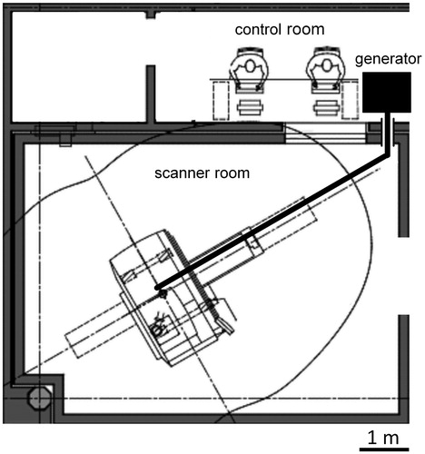
Percutaneous radiofrequency (RF) ablation is a common minimally invasive treatment option for patients with primary or secondary hepatic malignancies who are not amenable to surgical resection due to comorbidity, limited hepatic function or unfavourable anatomic conditions [Citation1,Citation2]. However, it has been shown that tumour size over 3 cm and location close to large vessels are critical factors for recurrence-free RF ablation [Citation3,Citation4]. In this respect, microwave ablation has developed into an alternative to RF ablation with advantageous physical properties [Citation5]. Compared with RF ablation, microwave ablation is not limited by charring around the applicator, thus higher intratumoral temperatures can be reached. This enables the creation of larger ablation zones in a shorter time with a single applicator [Citation6]. Furthermore, microwave energy is directly transmitted to a larger target volume, resulting in reduced susceptibility to the heat sink effect [Citation7]. First clinical applications of microwave ablation technique were impaired by technical problems such as power loss at the cable and critical heating of the antenna shaft, causing elongated ablation zones [Citation8,Citation9]. However, the latest generation of microwave ablation systems has overcome these problems and produces sufficiently large, spherical ablation zones without risk of accidental tissue heating [Citation10]. Most common guidance modalities for thermo-applicator placement are computed tomography (CT) and ultrasound; however, magnetic resonance imaging (MRI) offers several advantages such as near real-time fluoroscopic sequences [Citation11], free selection of imaging planes [Citation12], higher sensitivity in depicting small parenchymal lesions [Citation13], assessment of the ablation zone without application of contrast agent and absence of ionising radiation [Citation14]. A recent pre-clinical study has addressed the MR artefact configuration of a MR-compatible prototype microwave applicator [Citation15]. The authors stated that the microwave applicator’s artefacts are precise regarding the tip depiction and that the artefact appearance is independent from the angulation to the main magnetic field. A further technical prerequisite for MR-guided microwave ablation is the energy transmission from the generator to the patient positioned in the MR scanner, as the generator must be placed a safe distance away from the MR scanner (). This is a critical point due to energy loss along the extended transmission cable.
Figure 1. Floor plan of an MR suite at the author’s institute used for MR-guided microwave ablation. The microwave generator is positioned in the control room which is connected with the scanner room via a cable tunnel. A 6 m coaxial cable is necessary to reach the patient in the centre of the scanner.
The purpose of this study was the pre-clinical evaluation of a newly developed MR-compatible microwave ablation system designed for long-range energy transmission, focussing on ablation performance and comparison with a corresponding standard microwave ablation system.
Materials and methods
Microwave tissue ablation technique and equipment
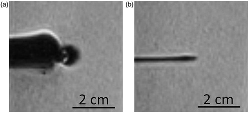
All experiments were conducted with a commercially available, non-cooled microwave ablation system with a maximum antenna power of 36 W (Medwaves Avecure™ Microwave Generator, Medwaves, San Diego, CA). Ablations were performed under temperature control mode: the generator automatically varied the length of the duty cycles of the pulsed output power and the microwave frequency (range from 902 to 928 MHz) to achieve and maintain an operator-selected ablation temperature during the pre-selected ablation period [Citation16]. The temperature at the ablation zone was constantly measured using an integrated sensor in the antenna shaft located 2 mm proximal to the active tip (). The ablations were performed using three 16 G microwave antennas with a shaft length of 16 cm: two MR-compatible antennas with active tip lengths of 2 cm (16–15-LH-15 (MR), Medwaves) and 4 cm (16–15-LH-35 (MR), Medwaves), respectively, and a non-MR-compatible standard antenna with an active tip length of 2 cm (16–15-LH-15, Medwaves). Ablations with the long active tip antenna were performed with a maximum antenna power of 36 W at the duty cycle; ablations with the short active tip antenna were performed with a maximum antenna power of 30 W at the duty cycle. displays the appearance of the standard microwave antenna and the MR-compatible microwave antenna in a T1-weighted Volumetric Interpolated Breath-hold Examination sequence (TE 1.3 ms, TR 3.6 ms, slice thickness 2 mm, matrix: 256 × 140, flip angle: 10°), acquired with a 1.5-T MR scanner (Magnetom ESPREE, Siemens, Erlangen, Germany) using a four-channel body-array surface coil. The antenna was connected to the generator via a 2.4 m coaxial cable. An additional 3.6 m coaxial cable was interposed for ablations with the MR-compatible antenna, to allow safe placement of the microwave generator outside the scanner room. The microwave ablation system manufacturer supported this study by providing the equipment. All experiments were performed by R.H. (six years of experience in ablation therapy). Results were only made available to the manufacturer after completion of the experiments.
Figure 2. MR-compatible microwave antenna (16–15-LH-15 (MR)) with a 4 cm active tip. The position of the integrated temperature sensor is marked.
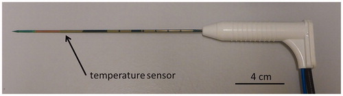
Figure 3. MR-Artefact of the standard (a) and the MR-compatible antenna (b) acquired with a T1-weighted Volumetric Interpolated Breath-hold Examination (T1 VIBE).
Ablation protocols
Ablations were performed at room temperature using fresh bovine liver obtained from a local abattoir. Before installation of the antennas under direct view, large hepatic veins were explored with a metal probe to avoid close positioning. In accordance with the manufacturer’s recommendations, the ablations with the 2 cm active tip antenna (“short active tip”) and the 4 cm active tip antenna (“long active tip”) were conducted with a target temperature of 110 and 120 °C, respectively. The following ablation settings were applied: [A] Standard antenna, 2 cm active tip, 2.4 m cable; [B] MR-compatible antenna, 2 cm active tip, 2.4 m cable; [C] MR-compatible antenna, 2 cm active tip, extended 6 m cable; and [D] MR-compatible antenna, 4 cm active tip, extended 6 m cable. Ablation durations were 3, 5 and 10 min for setting [A], [B] and [C], and 3, 5, 10 and 15 min for setting [D]. Each combination was repeated four times, resulting in a total of 52 ablations.
Assessment of coagulation zone
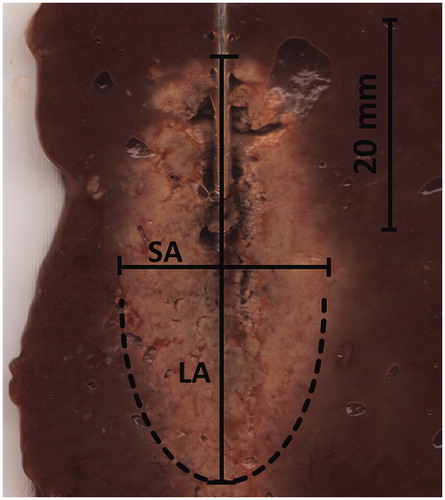
After ablation, the antenna was replaced with a metal bar and the ablated tissue was sectioned along the bar and optically scanned (PIXMA MP160, Canon, Tokyo, Japan). The saved electronic images were analysed using graphic viewer software (IrfanView, Version 4.37, www.irfanview.com). Diameters of the ablation zone were measured referring to the size of white coagulation. The diameter along the antenna insertion axis was defined as long axis diameter (LA); the short axis diameter (SA) was orientated perpendicular to the long axis (). The coagulation volume (V) was calculated using the formula for ellipsoids: V = (π/6)(LA)(SA)2. The shape of the ablation zone was stated using the sphericity index, determined by calculating the ratio between SA and LA.
Figure 4. Coagulation zone after 5 min of ablation with the MR-compatible short active tip antenna. Short axis diameter (SA) and long axis diameter (LA) are depicted.
Statistical analysis
To assess the influence of the MR-compatible antenna and the extension coaxial-cable on the ablation performance, we compared the SA and the V of the ablation zone and the generator energy output (E) of the three settings [A], [B] and [C]. Analysis of variance (ANOVA) and post hoc testing with Tukey–Kramer honest significant difference (HSD) were performed separately to evaluate differences for the ablation durations 3, 5 and 10 min.
Ablation performance of the MR-compatible system (MR-compatible antenna including the extended connection cable) was tested with the short active tip and long active tip MR-compatible antennas, respectively (setting [C] and [D]). Unpaired t-test was conducted for comparison of the ablation results after 3, 5 and 10 min regarding SA, V, E and sphericity index (SA/LA). Statistical analysis was conducted using JMP (JMP 11.1.1, SAS Institute, Cary, NC). A p value of <0.05 was considered statistically significant. Results are stated as mean ± standard deviation (SD).
Results
There was no statistically significant difference concerning short axis diameter and ablation volume when comparing the 16 G standard antenna (setting [A]) and the 16 G MR-compatible antenna (setting [B]), each with a 2.4 m connector cable (). Cable extension to 6 m length (setting [C]) did not significantly affect the ablation results with a mean short axis diameter of 25.0 ± 2.0 mm with 10 min ablations, compared to 25.8 ± 2.4 mm for the standard antenna and 25.3 ± 1.9 mm for the MR-compatible antenna, each with a 2.4 m connector cable (ANOVA: p = 0.88). Similarly, there was no statistically significant effect on short axis diameter or ablation volume for shorter ablation durations (). Whereas ablations with a 2.4 m connector cable required an equal energy amount, the energy amount was significantly higher when the MR-compatible antenna was used with the extension cable (10 min ablation; [A]: 9.9 ± 0.5 kJ, [B]: 10.1 ± 0.5 kJ, p = 0.84), [C] 13.1 ± 0.3 kJ, p < 0.001). This higher energy amount was reached by an automatic adaption of the pulsed output rate with longer duty cycles. Consequently, the calculated average power rose from 16.8 to 21.8 W in the 10 min ablations with the 3.6 m extension cable. Results were similar for shorter ablation durations ().
Figure 5. Short axis diameter (a), volume of the ablation zone (b) and energy output (c) after 10 min of ablation time with the [A] Standard antenna, 2 cm active tip, 2.4 m cable, [B] MR-compatible antenna, 2 cm active tip, 2.4 m cable and [C] MR-compatible antenna, 2 cm active tip, extended 6 m cable. Error bars indicate the 95% confidence interval.
![Figure 5. Short axis diameter (a), volume of the ablation zone (b) and energy output (c) after 10 min of ablation time with the [A] Standard antenna, 2 cm active tip, 2.4 m cable, [B] MR-compatible antenna, 2 cm active tip, 2.4 m cable and [C] MR-compatible antenna, 2 cm active tip, extended 6 m cable. Error bars indicate the 95% confidence interval.](/cms/asset/fc1fe0a5-737b-4ac9-ae30-e81226b03026/ihyt_a_1284349_f0005_b.jpg)
Table 1. Comparison of the ablation results of the standard device and the MR-compatible device.
summarises the ablation results of both MR-compatible antennas with extended cable ([C] and [D]) with regard to SA, V and sphericity index in relation to ablation duration. For short ablation duration of 3 min, the long active tip antenna showed a tendency to produce ablation zones with a smaller sphericity index ([C]: SA/LA = 0.4 ± 0.02, [D]: SA/LA = 0.36 ± 0.3, p = 0.06). However, this tendency changes to the opposite for longer ablation durations. The long active tip antenna created larger ablation zones with significantly larger short axis diameters (5 min: 19.5 ± 0.6 mm [C], 27.0 ± 1.0 mm [D], p < 0.001; 10 min: 25.0 ± 2.0 mm [C], 34.0 ± 2.9 mm [D], p = 0.003) and larger ablation volumes (5 min: 8.1 ± 0.7 cm³ [C], 21.6 ± 2.4 cm³ [D], p < 0.001; 10 min: 17.8 ± 2.7 cm³ [C], 39.4 ± 7.5 cm³ [D], p = 0.007). The long active tip antenna reached the largest and most spherical ablation zone after 15 min ablation duration with a mean short axis diameter of 41.0 ± 1.4 mm.
Table 2. Ablation results of both MR-compatible antennas (with short active tip and long active tip) under use of the extended cable.
Discussion
In the advent of microwave ablation, devices produced predominantly small and elongated ablation zones with maximum diameters slightly greater than 2 cm. Therefore, applicator repositioning was necessary for successful treatment of larger tumours [Citation17]. However, the latest generation of microwave ablation systems is capable of producing larger and more spherical ablation zones and microwave ablation has found its way into clinical routine [Citation18,Citation19]. Using MRI as a guidance modality in percutaneous ablation procedures is currently limited to a few centres specialised in MR-guided interventions, even though MR-guidance offers several advantages such as near real-time fluoroscopic sequences [Citation11], free selection of imaging planes [Citation12], higher sensitivity in depicting small parenchymal lesions [Citation13], assessment of the ablation zone without application of contrast agent and absence of ionising radiation [Citation14]. The high operating costs of dedicated MRI-scanners combined with longer durations of MR-guided interventions prevent the increased use of MR-guidance in interventional oncology [Citation20]. However, the combination of microwave ablation and MR-guidance might be beneficial, as microwave ablation creates larger ablation zones in shorter time and with less applicator insertions than RF ablation [Citation6,Citation21,Citation22]. A recent study by Ziemlewicz et al. reported on 75 patients who were treated with microwave ablation for 107 hepatocellular carcinomas (HCC) with a mean tumour diameter of 2.5 cm (range 0.5–7.0 cm), a mean ablation duration of only 5.3 min (range 1–13 min) and a technical success rate of 100% [Citation23]. In comparison, Kang et al. reported on 183 patients who were treated with RF ablation for non-perivascular HCC with a mean diameter of 2.0 cm (±0.54 cm), mean ablation duration of 14.1 min (±5.0 min) and a technical success rate of 97.3% [Citation24]. A systematic review and meta-analysis by Facciorusso et al. showed similar efficacy between RF ablation and microwave ablation with an apparent superiority of microwave ablation in larger neoplasms [Citation25]. Another advantage of microwave ablation in comparison to RF ablation is the higher technical compatibility with MRI. The frequency of RF ablation generators interferes with the MR scanner making imaging during the ablation procedure impossible without the use of additional filters [Citation13,Citation26]. However, microwave ablation generators work at higher frequencies of 915 MHz or 2.45 GHz, which may improve imaging control during an on-going ablation procedure [Citation27].
A general prerequisite for a MR-compatible microwave antenna is a similar ablation performance to a standard, non-MR-compatible microwave antenna. This was confirmed in our tests. No significant difference was detected between the MR-compatible short active tip antenna and the corresponding standard antenna regarding SA and ablation zone volume. Analogous comparisons with regard to the MR-compatible long active tip antenna could not be conducted in this study, as a 16 G standard antenna with a 4 cm active tip is not yet available. Current microwave systems dedicated for CT- or ultrasound guidance are constructed for generator positioning close to the patient, thus regular cable lengths do not exceed 3 m. Two technical approaches are imaginable for MR-guided MW-ablations: an electromagnetically shielded, non-ferromagnetic microwave generator with shielded transmission cables which enable positioning close to the MR scanner or energy transmission from a microwave generator positioned outside the MR scanner room. The latter approach with a long range energy transmission was the subject of this study. However, long range energy transmission is a critical point, since power loss along the transmission cable is related to the cable dimensions [Citation28]. Power loss of a coaxial cable increases with cable length and decreases with cable diameter. However, the cable diameter cannot be unconditionally enlarged in clinical use, as coaxial cable diameters affect the cable’s flexibility [Citation29]. We conducted our experiments using a 3.6 m cable extension resulting in a total length of 6 m, which was considered as sufficient for most MRI scanners to enable positioning of the generator outside the scanner room. With this MR-compatible setting, applied energy was increased by 11–30% in comparison to the standard cable length. As a result of this, no significant difference of the MR-compatible setting compared to the standard setting was found regarding SA and coagulation volume.
This result can be explained by an automatic elevation of the average power executed by the generator to maintain the operator-selected ablation temperature. The higher average power was reached with longer duty cycles of the pulsed output power without exceeding the pre-selected maximum power. This is an essential point, since further elevation of the maximum power would necessitate additional cooling of the applicator’s shaft to avoid the risk of thermal injury to structures along the applicator track [Citation30].
Both the short active tip and long active tip MR-compatible antenna created ablation zones with a sphericity index of approximately 0.5 for ablation durations of 5 min or longer. A recent ex vivo study reported similar results for a comparable non-MR-compatible MW-system with a sphericity index of 0.54 for 5 min ablations [Citation31]. However, both devices generated more elongated ablation zones for shorter ablation durations with a sphericity index ≤0.4 in our study. The treatment of relatively small lesions might therefore be complicated in clinical use if the target lesion is located close to delicate structures due to the need to over-size the ablation zone in the applicator axis direction.
The major limitation of this study is the use of an ex vivo liver model. Even if microwave ablation is less susceptible to the cooling effect of tissue vascularisation than RF ablation, this ex vivo study is limited by the absence of tissue perfusion [Citation32]. Ex vivo ablations have a tendency to overestimate the size of the ablation zone in comparison to in vivo ablations, especially in longer ablations [Citation33]. We determined the size of the ablation zones after treatment. This zone is smaller than the untreated tissue because ablated tissue shrinks, resulting in an underestimation of the ablated tissue. Finally, this study only referred to the ablation performance of the MR-compatible system; nevertheless, tests concerning the MR-artefact appearance of the antenna are necessary before clinical application.
In conclusion, the MR-compatible microwave antenna and a standard, comparable non-MR-compatible microwave ablation device create similar ablation zones. Furthermore, use of an extension cable for generator positioning outside the MR scanner room was successfully compensated by an automatic increase in the average generator power and resulted in similar ablation zones to the standard setting without statistically significant differences. These results are prerequisites for clinical use of MR-guided microwave ablation; however, further studies are necessary to investigate the potential advantages of the combination of both techniques.
Acknowledgements
The authors thank Mr. Ted Ormsby (Medwaves, San Diego, CA) for supporting this study by providing the ablation equipment.
Disclosure statement
The authors declare no conflict of interest.
References
- Solbiati L, Ahmed M, Cova L, et al. (2012). Small liver colorectal metastases treated with percutaneous radiofrequency ablation: local response rate and long-term survival with up to 10-year follow-up. Radiology 265:958–68.
- Meloni MF, Chiang J, Laeseke PF, et al. (2016). Microwave ablation in primary and secondary liver tumours: technical and clinical approaches. Int J Hyperthermia 2:1–10.
- Kang TW, Lim HK, Lee MW, et al. (2015). Aggressive intrasegmental recurrence of hepatocellular carcinoma after radiofrequency ablation: risk factors and clinical significance. Radiology 276:274–85.
- Poch FG, Rieder C, Ballhausen H, et al. (2016). The vascular cooling effect in hepatic multipolar radiofrequency ablation leads to incomplete ablation ex vivo. Int J Hyperthermia 32:749–56.
- Yu J, Liang P. (2016). Status and advancement of microwave ablation in China. Int J Hyperthermia 4:1–41.
- Fan W, Li X, Zhang L, et al. (2012). Comparison of microwave ablation and multipolar radiofrequency ablation in vivo using two internally cooled probes. Am J Roentgenol 198:46–50.
- Andreano A, Brace CL. (2013). A comparison of direct heating during radiofrequency and microwave ablation in ex vivo liver. Cardiovasc Intervent Radiol 36:505–11.
- Ryan TP, Brace CL. (2016). Interstitial microwave treatment for cancer: historical basis and current techniques in antenna design and performance. Int J Hyperthermia 28:1–12.
- Lubner MG, Brace CL, Hinshaw JL, Lee FT Jr. (2010). Microwave tumor ablation: mechanism of action, clinical results, and devices. J Vasc Interv Radiol 21:192–203.
- Huo YR, Eslick GD. (2015). Microwave ablation compared to radiofrequency ablation for hepatic lesions: a meta analysis. J Vasc Interv Radiol 26:1139–46.
- Rempp H, Loh H, Hoffmann R, et al. (2014). Liver lesion conspicuity during real-time MR-guided radiofrequency applicator placement using spoiled gradient echo and balanced steady-state free precession imaging. J Magn Reson Imaging 40:432–9.
- Clasen S, Pereira PL. (2008). Magnetic resonance guidance for radiofrequency ablation of liver tumors. J Magn Reson Imaging 27:421–33.
- Terraz S, Cernicanu A, Lepetit-Coiffe M, et al. (2010). Radiofrequency ablation of small liver malignancies under magnetic resonance guidance: progress in targeting and preliminary observations with temperature monitoring. Eur Radiol 20:886–97.
- Rempp H, Unterberg J, Hoffmann R, et al. (2013). Therapy monitoring of magnetic resonance-guided radiofrequency ablation using T1- and T2-weighted sequences at 1.5 T: reliability of estimated ablation zones. Invest Radiol 48:429–36.
- Hoffmann R, Rempp H, Eibofner F, et al. (2016). In vitro artefact assessment of a new MR-compatible microwave antenna and a standard MR-compatible radiofrequency ablation electrode for tumour ablation. Eur Radiol 26:771–9.
- Sommer CM, Arnegger F, Koch V, et al. (2012). Microwave ablation of porcine kidneys in vivo: effect of two different ablation modes (“temperature control” and “power control”) on procedural outcome. Cardiovasc Intervent Radiol 35:653–60.
- Dodd GD 3rd, Soulen MC, Kane RA, et al. (2000). Minimally invasive treatment of malignant hepatic tumors: at the threshold of a major breakthrough. Radiographics 20:9–27.
- Vogl TJ, Farshid P, Naguib NN, et al. (2015). Ablation therapy of hepatocellular carcinoma: a comparative study between radiofrequency and microwave ablation. Abdom Imaging 40:1829–37.
- Ding J, Jing X, Liu J, et al. (2013). Comparison of two different thermal techniques for the treatment of hepatocellular carcinoma. Eur J Radiol 82:1379–84.
- Maurer MH, Froeling V, Rottgen R, et al. (2014). MRI-guided and CT-guided cervical nerve root infiltration therapy: a cost comparison. Rofo 186:559–66.
- Yu J, Liang P, Yu X, et al. (2011). A comparison of microwave ablation and bipolar radiofrequency ablation both with an internally cooled probe: results in ex vivo and in vivo porcine livers. Eur J Radiol 79:124–30.
- Rempp H, Waibel L, Hoffmann R, et al. (2012). MR-guided radiofrequency ablation using a wide-bore 1.5-T MR system: clinical results of 213 treated liver lesions. Eur Radiol 22:1972–82.
- Ziemlewicz TJ, Hinshaw JL, Lubner MG, et al. (2015). Percutaneous microwave ablation of hepatocellular carcinoma with a gas-cooled system: initial clinical results with 107 tumors. J Vasc Interv Radiol 26:62–8.
- Kang TW, Lim HK, Lee MW, et al. (2014). Perivascular versus nonperivascular small HCC treated with percutaneous RF ablation: retrospective comparison of long-term therapeutic outcomes. Radiology 270:888–99.
- Facciorusso A, Di Maso M, Muscatiello N. (2016). Microwave ablation versus radiofrequency ablation for the treatment of hepatocellular carcinoma: a systematic review and meta-analysis. Int J Hyperthermia 32:339–44.
- Fischbach F, Lohfink K, Gaffke G, et al. (2013). Magnetic resonance-guided freehand radiofrequency ablation of malignant liver lesions: a new simplified and time-efficient approach using an interactive open magnetic resonance scan platform and hepatocyte-specific contrast agent. Invest Radiol 48:422–8.
- Kaltenbach B, Roman A, Eichler K, et al. (2016). Real-time qualitative MR monitoring of microwave ablation in ex vivo livers. Int J Hyperthermia 32:757–64.
- Brace CL. (2009). Microwave ablation technology: what every user should know. Curr Probl Diagn Radiol 38:61–7.
- Brace CL. (2010). Microwave tissue ablation: biophysics, technology, and applications. Crit Rev Biomed Eng 38:65–78.
- Lubner MG, Hinshaw JL, Andreano A, et al. (2012). High-powered microwave ablation with a small-gauge, gas-cooled antenna: initial ex vivo and in vivo results. J Vasc Interv Radiol 23:405–11.
- Hoffmann R, Rempp H, Erhard L, et al. (2013). Comparison of four microwave ablation devices: an experimental study in ex vivo bovine liver. Radiology 268:89–97.
- Amabile C, Farina L, Lopresto V, et al. (2016). Tissue shrinkage in microwave ablation of liver: an ex vivo predictive model. Int J Hyperthermia 20:1–9.
- Hines-Peralta AU, Pirani N, Clegg P, et al. (2006). Microwave ablation: results with a 2.45-GHz applicator in ex vivo bovine and in vivo porcine liver. Radiology239:94–102.