
Abstract
Purpose: HIFU has been emerging as an effective and safe modality for the treatment of solid tumours and cancers. The focus shifting range of phased array HIFU transducer is an important safety concern because of the presence of grating lobe in the pre-focal region. However, previous studies were only based on linear acoustic wave model.
Materials and methods: The nonlinear wave propagation from a 256-element phased array through multiple layered media was simulated using the angular spectrum approach (ASA) in marching fractional steps with the consideration of diffraction, attenuation and non-linearity effects by a second-order operator splitting scheme. The distribution of acoustic intensities, temperature elevations, lesion sizes and grating lobe levels were calculated at various axially post-focal shifting distances and driving frequencies.
Results: Axially shifting HIFU focus leads to significant increase of the acoustic intensity at the grating lobe, but decrease at the main lobe. The influences on the acoustic field, thermal field and lesion sizes are determined by the shifting distance and driving frequency, and variations can be fit monotonically and linearly. Prediction accuracies by simple regression models are satisfactory. Irreversible tissue coagulation could be generated by the grating lobe at certain conditions.
Conclusions: The established nonlinear wave propagation algorithm allows the accurate description of HIFU field and consequently the evaluation of grating lobe and steerability of focus. The influence of focus shifting may be predicted simply. The treatment planning of phased array HIFU ablation could be optimised by setting the appropriate exposure and focus scanning schemes.
Introduction
High-intensity focussed ultrasound (HIFU) has been used safely and effectively for thousands of patients worldwide with either benign or malignant tumours since 1990s [Citation1]. Compared with the other ablative modalities, HIFU ablation is the really non-invasive option with the fewest complications. There is theoretically no upper limit of the HIFU retreatment sessions [Citation2]. In addition to curative treatment and the extension of life expectancy, HIFU can reduce or eliminate the tumour-related pain and thus improve the quality of life for patients, especially those with cancer metastasis. Focusing the ultrasound beam is one of the key issues. Self-focussing using a spherically concave transducer or the use of acoustic lenses in front of flat transducer generates a fixed and single focus at the position determined by the geometrical specifications. HIFU focus should be scanned mechanically throughout the whole target. Although such approach is reliable and simple in the control, the motor motion speed is low, which may lead to impractically long treatment duration. The other scheme is the use of a phased array [Citation3]. By the control of driving signals (the amplitude and phase) to each element, beam shifting, beam shape reshaping, and formation of multiple foci could be achieved. The interval time between sonication points is shortened dramatically, allowing a rapid dynamic control of the focussing and a real-time tracking of the respiratory-induced organ motion (e.g. kidney and liver) [Citation4]. The phased array can also correct the wave aberration due to its propagation through heterogeneous media and avoid the obstacles (e.g. ribs), making it more versatile and flexible.
Several studies have already shown that near-field thermal build-up or secondary maximum occurs in the proximal tissues for the skin burn when executing the HIFU ablation using a phased array transducer [Citation5,Citation6]. Such heating could be mitigated by active cooling or by slowing down the treatment time, but neither of them is ideal. The grating lobe is mainly due to the overlap of the acoustic beam. If the focus is shifted away from the geometrical focal point, a reduction in the acoustic intensity at the focus and simultaneous increase of the grating lobes will occur, and the influence becomes significant with the shifting distance [Citation7]. Therefore, the accepted steering range is a key metric for the phased array with regard to its safety and efficacy. A good understanding of the relationship between the focus shifting distance and the grating lobe or the main lobe can provide valuable guidelines for the design of phased array transducer and HIFU treatment planning, particularly in determining the trade-offs between the transducer complexity and the desired beam characteristics for a specific clinical application. In the numerical simulation, it is found that shifting the focus of concave phased array in one direction will cause the grating lobe to grow symmetrically in the opposite direction [Citation8]. Therefore, steering the focus in the post-focal region will further enhance the grating lobe in the pre-focal region, which is greatly undesired. In addition, the focus steering is only feasible in the axial direction for the concentric-ring array [Citation9,Citation10].
In most of the studies for the grating lobe [Citation11–13], the acoustic pressure was often calculated using a form of the Rayleigh–Sommerfeld sum based on the linear acoustic wave propagation. The FIELD II programme [Citation14] and the fast near-field method (FNM) [Citation15] were also used. However, because of high power applied to HIFU transducer, nonlinear acoustic effect during the wave propagation towards the focus is never negligible, leading to the production of high order harmonics and distortion of the waveform or an even abrupt rise of positive pressure (shock front). As the acoustic absorption is proportional to the frequency, the enhancement ratio of absorbed acoustic energy at the beam focus of HIFU transducer increases significantly, which leads to the temperature rise up to 100 °C in milliseconds during HIFU sonication to produce large boiling bubbles [Citation16]. Meanwhile, −6 dB beam size also varies with the acoustic intensity at the focal point [Citation17]. In our previous study, an angular spectrum approach (ASA) with marching fractional steps was applied in the wave propagation from phased-array HIFU transducer, and diffraction, attenuation, and non-linearity effects were accounted for by a second-order operator splitting scheme [Citation18]. Better agreement was found between the measured harmonics distribution and simulation using the proposed algorithm than the Khokhlov–Zabozotskaya–Kuznetsov (KZK) equation. Various focussing strategies (geometric focussing, transverse shifting and the generation of multiple foci) through multiple-layered media can be simulated from the transducer with an arbitrary shape in high computation accuracy. The shifting and splitting of focus were found to result in significantly less temperature elevation at the focus, and subsequently, the smaller the lesion size the larger the grating lobe in the pre-focal region.
In this study, the effect of axial focus shifting on both the acoustic and thermal field within a small range around the resonant frequency was investigated. The nonlinear acoustic wave propagation from a 256-element phased array HIFU transducer through multiple-layered media was simulated using the established ASA algorithm. Temperature elevations induced by the HIFU ablation (2 s exposure followed by 3 s cooling) was then calculated using the BioHeat equation, from which the lesion area and volume were determined. The safety concern related to the grating lobe was notified at the various axial focus shifting distances from 0 cm to 2.5 cm and driving frequency from 0.9 MHz to 1.1 MHz. The grating lobe level defined as the ratio of the acoustic intensity of the grating lobe to that of the main lobe in decibel and the thermal dose at the grating lobe was used to evaluate the potential of injury. Simple regressions could be fitted to the calculated values (e.g. acoustic intensity and temperature elevation) for easy and quick estimation of HIFU planning.
Materials and methods
HIFU-phased array
To simulate the HIFU ablation for the deep-seated tissue (e.g. liver), a 256-element spherically focussed phased array transducer (H-169, a focal length of 200 mm, an active diameter of 200 mm, a central opening of 64 mm, the central frequency of 1 MHz, Sonic Concepts, Bothell, WA) was used. Circular elements with the diameter of 1 cm are regularly allocated on the concave surface. A multiple layer model modified from the human abdomen was used in the simulation (see ). Physical properties of all media used in the simulation are from the previous studies [Citation18] and listed in . To include a pronounced nonlinear effect in the acoustic wave propagation, the acoustic pressure at the transducer surface was set as 300 kPa (3 W/cm2). In addition, the driving frequency of the HIFU transducer was in a small region of its resonant frequency (e.g. from 0.9 MHz to 1.1 MHz in a step size of 0.05 MHz).
Figure 1. Schematic diagram of the multiple-layered model and coordinate used in the simulation. z: axial direction, x, y: lateral directions.
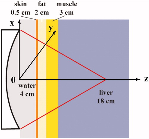
Table 1. Acoustic properties of materials used in the simulation.
Acoustic model
The pressure field generated by a harmonically excited circular element is given by the FNM with the coordinate system aligned at the element centre [Citation15]:
(1)
where a is the radius of the element, u0 is the velocity on the element surface. This approach allows the easy 1-D integral over ψ by the middle-point Riemann sum. The element response function array (ERFA) method [Citation19] was used to calculate the initial plane pressure, 1.5 mm in front of the aperture. The response of each transducer element was stored as a separate page in a 3 D array and repeated for the others, resulting in 256 pages for the 256-element array. The initial pressure plane is the sum of all pages, and then the nonlinear wave propagation was simulated using the proposed ASA algorithm [Citation18]. Briefly, the propagation of finite-amplitude acoustic waves over incremental distance, Δz, was accomplished by first solving a half-step with the diffraction operator, then a full step with non-linearity and attenuation operator, and finally another half-step with the diffraction operator [Citation18,Citation20].
(2)
The pressure could be derived from the 2-D spatial convolution between the input pressure at z0 and the spatial propagator hp.
(3)
Performing 2-D Fourier transforms on both sides of Equation (Equation3(3) ) obtains
(4)
Hp(kx,ky,Δz;ω) is given by the analytical Hankel transform of hp(x,y,Δz;ω).
(5)
The spatial sampling interval along the x and y direction is both 0.2 mm (1024 × 1024 grid on the transverse plane), and the angular spectrum of the input plane is calculated using a 2-D FFT. Meanwhile, the axial spatial sampling intervals vary in the different media (1/5 – 1/3 of wavelength): λw/4 (46 grids) in water, λs/5 (12 grids) in skin, λf/4 (39 grids) in fat, λm/4 (52 grids) in muscle and λl/3 (276 grids) in liver, respectively. Distortion of finite-amplitude wave occurs in the propagation due to convective and nonlinear effects over incremental steps, which can be expressed as given in reference [Citation21]:
(6)
where β is the nonlinearity coefficient, f0 is the driving frequency and the frequency dependence of the attenuation coefficient is given by α(f)=α0fb. The maximum number of harmonics retained in the simulation was up to 20, which was large enough for the significant waveform distortion due to the apparent nonlinear acoustic effect [Citation18].
The 3-D ERFA array was pre-calculated for unit amplitude and zero phase on all elements. The phases applied to the elements for the desired focus shifting are calculated by the Huygen’s principle. The pseudo-inverse approach was applied to determine the final driving signal using the weighted minimum-norm solution for a full rank matrix [Citation3]. An iterative weighting algorithm was utilised to achieve the specified power deposition at the desired focal location with nearly 100% array excitation efficiency. The refraction occurring at the tissue interface was compensated by backward propagating the acoustic field towards the transducer surface [Citation18]. Each page of ERFA was multiplied with its respective phase and amplitude. HIFU focus was only steered axially and post-focally with the shifting distances from 0 cm (geometric focus) to 2.5 cm.
Thermal model
The Bio-Heat transfer equation (BHTE) was used to simulate the temperature elevation and lesion formation by HIFU [Citation22]:
(7)
where ρ is the density of the tissue, Ct is the specific heat of the tissue, T is the temperature at time t, κ is the thermal conductivity, Cb is the specific heat of the blood, Wb is the blood perfusion rate, Ta is the temperature at large distances, which corresponds to the initial condition value and Qp is the power deposited from the focussed ultrasound beam:
(8)
The thermal properties of the liver are as follows: Ct = 3628 J/kg/°C, Cb = 3628 J/kg/°C, κ = 0.465 W/m/°C, Wb = 10 kg/m3/s, Ta = 37 °C [Citation18]. The BHTE was solved using the finite-difference time-domain (FDTD) method in a temporal step size of 0.01 s with the initial and boundary conditions of 37 °C. The thermal dose, an equivalent exposure time at 43 °C (CEM43), is used to characterise the ablation outcome [Citation23].
(9)
where R is 0.5 for T ≥ 43 °C and 0.25 for T < 43 °C. The lesion formation requires a thermal dose of a 240-min exposure at 43 °C (240D43). The schemes for the HIFU ablation were 2 s-heating followed by 3 s-cooling. All the simulations ran in MATLAB (R2010b, Mathworks, Natick, MA) on a PC (3.3 GHz IntelVR CoreTM i5–2500 CPU, 4 GB RAM) with Windows 7 32-bit operating system.
Performance prediction
The simulated key performances of phased-array HIFU ablation at the varied axially post-focal shifting distances in this study, such as the acoustic and thermal field characteristics (e.g. acoustic intensity, temperature elevation, thermal dose and lesion volume), could be fitted by some simple regression models (e.g. linear and exponential growth functions). Using such regression models, the performance could be predicted easily without time-consuming calculation at the same output power. The prediction errors, which are defined as the percentages of the difference between the calculated and predicted values with respect to the calculated values, were used for the quantitative evaluation.
Results
Comparison between linear and nonlinear model
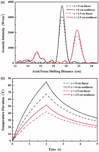
The axial distribution of acoustic intensity and the temperature elevation at the focus using the linear acoustic model was simulated by turning off the nonlinear term in the ASA algorithm and then compared with the results using the proposed nonlinear model as shown in . With the increase of axial focus shifting distance, the acoustic intensity at the synthesised focus decreases while that at the grating lobe increased. If the nonlinear wave propagation is considered in the simulation, the increases of acoustic intensity at the focus are almost the same (by 1.21-fold, 3099 vs. 3752 W/cm2 at the geometric focus, and 1813 vs. 2176 W/cm2 at the axial focus shifting distance of 2.5 cm). In comparison, the corresponding increases at the grating lobe are a little smaller (by 1.12-fold, 147 vs. 165 W/cm2 and 681 vs. 765 W/cm2, respectively). As a result, the grating lobe levels predicted by the nonlinear model are slightly lower than those by the linear model (−13.6 dB vs. −13.2 dB at the geometric focus and −4.5 dB vs. −4.3 dB at axial focus shifting distance of 2.5 cm, respectively). Meanwhile, significant differences in the temperature elevations by 2 s-HIFU exposure were also found using the predicted acoustic intensity and absorbed acoustic energy by the linear and nonlinear model (see ). The maximum temperature elevations increased by 1.26-fold (67.8 °C vs. 85.2 °C) and 1.23 fold (42.1 °C vs. 52 °C) at the geometric focus and at the axial focus shifting distance of 2.5 cm, respectively. Therefore, in order to accurately describe the acoustic and thermal field generated by the phased array HIFU transducer nonlinear acoustic wave model is required, which is similar to the conclusion from single-element HIFU transducer [Citation24,Citation25].
Figure 2. Comparison of the axial distribution of acoustic pressure with the axial focus shifting distance of 0 cm and 2.5 cm predicted by nonlinear (solid line) and linear (dashed line) acoustic model.
Acoustic field
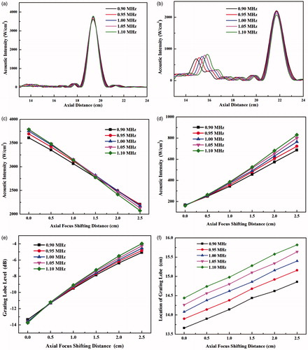
The axial plane (xz) distributions of the acoustic intensity at different frequencies are shown in the left column of . It is found that the synthesised main lobe is small in both axial and lateral direction at the high driving frequency, but the grating lobe becomes significant and locates close to the main lobe. As the synthesised focus is shifted along the transducer axis, the grating lobe also appears on the axis. The axial distribution of acoustic intensity and the peak values at the main lobe and the grating lobe with the various axial focus shifting distances and driving frequencies are shown in . The acoustic intensity at the geometric focus of the HIFU transducer increases slightly with the driving frequency, from 3610 W/cm2 at 0.9 MHz to 3788 W/cm2 at 1.1 MHz. −3 dB intensity or −6 dB pressure beam length decreases from 7.9 mm at 0.9 MHz to 6.5 mm at 1.1 MHz. With the increase of axial focus shifting distance, the acoustic intensity at the main lobe decreases gradually. At the axial focus shifting distance of 2.5 cm, the acoustic intensity at the steered main lobe decreases with the driving frequency from 2208 W/cm2 at 0.9 MHz to 2074 W/cm2 at 1.1 MHz, and such relationship with the driving frequency seems to reverse at the shifting distance of 1.5 cm (see ). The increase of −3 dB intensity beam length at the low frequency is larger, 1.24-fold and 1.16-fold at 0.9 MHz (from 7.9 mm to 9.8 mm) and 1.1 MHz (from 6.5 mm to 7.6 mm), respectively. In comparison, the grating lobe becomes significant with the axial focus shifting distance and larger than the side lobe. It suggests that large steering distance should be avoided for the concern of any side effects associated with the grating lobe. At the geometric focus, the acoustic intensity at the grating lobe decreases slightly with the driving frequency from 166.8 W/cm2 at 0.9 MHz to 160.1 W/cm2 at 1.1 MHz; whereas the corresponding value increases with the driving frequency from 686.8 W/cm2 to 831 W/cm2 at the axial focus shifting distance of 2.5 cm, and the turning occurs when the focus is steered only about 0.5 cm post-focally. Thus, the impact of frequency on the grating lobe is more significant than that on the main lobe. The increase of the grating lobe (4.6-fold at 1 MHz) is much higher than the decrease of the main lobe (1.7-fold) for the focus shifting axially by 2.5 cm. As a result, the grating lobe level increases from about −14 dB to −4 dB. The safe criterion of grating lobe level of −10 dB will not be met at the axial focus shifting distance larger than about 8 mm (see ). In addition, the location of grating lobe moves away from the transducer at the slope of about 0.4 cm/MHz at all driving frequencies with respect to the axial focus steering distance (see ). In addition, the increases of −3 dB intensity beam length of the grating lobe with the axial focus shifting distance at all driving frequencies are similar, 1.36-fold (from 4.9 mm to 6.6 mm) at 0.9 MHz and 1.34-fold (from 4.5 mm to 6.0 mm) at 1.1 MHz, respectively.
Figure 3. Comparison of the axial (xz) plane distribution of acoustic intensity (left column in unit of W/cm2) and temperature elevation (right column in unit of °C) at (a) 0.9 MHz and (b) 1.1 MHz with the geometrical focussing and at (c) 0.9 MHz and (d) 1.1 MHz with the axial focus shifting distance of 2.5 cm.
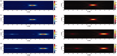
Figure 4. Axial acoustic intensity distribution with the axial focus shifting distance of (a) 0 cm and (b) 2.5 cm, variations of the acoustic intensity of (c) main lobe and (d) grating lobe, (e) the grating lobe level and (f) the location of grating lobe with the axial focus shifting distance varying from 0 cm to 2.5 cm and driving frequency varying from 0.9 MHz to 1.1 MHz.
Thermal patterns
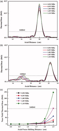
The thermal field during HIFU ablation and consequent lesion production were calculated. The pattern of thermal field is similar to that of acoustic intensity (see the right column of . The variations in the acoustic intensity by shifting the focus axially and driving frequency lead to the changes of temperature elevations in both the main lobe and grating lobe (see . The high driving frequency always has high-temperature elevation at all axial steering distances of HIFU focus. The maximum temperature elevations decrease quasi-linearly with the axial focus shifting distance, and the high driving frequency has a large decreasing rate (10.72 °C/cm at 0.9 MHz vs. 15.72 °C/cm at 1.1 MHz, see ). It suggests that the influence of the driving frequency on the thermal field decreases with the focus shifting distance. In contrast, the temperature elevation of the grating lobe increases quasi-linearly with the axial focus shifting distance, and high driving frequency has a large increasing rate (from 3.22 °C/cm at 0.9 MHz to 4.89 °C/cm at 1.1 MHz, see ). Subsequently, the axial distribution of the thermal dose was calculated (see . Although the maximum temperature elevation decreases with the axial focus shifting distance, large lesion could be produced at the low frequency due to the increased beam length. The increases of lesion length at all driving frequencies are similar, from 17.5 mm to 19.6 mm at 0.9 MHz and from 15.1 mm to 16.1 mm at 1.1 MHz, respectively. It is also found that the thermal dose at the grating lobe increases rapidly when the axial focus shifting distance is larger than 1.5 cm and could be larger than the threshold of tissue coagulation (240D43) at the frequency of 1.1 MHz and 1.05 MHz and axial focus shifting distance of 2.5 cm (see ). Therefore, there is a trade-off for the driving frequency during the HIFU ablation, the high frequency accelerating the focal heating and also greatly speeding up the undesirable heating of the grating lobe in the pre-focal region.
Figure 5. The temperature elevation of main lobe with the axial focus shifting distance of (a) 0 cm and (b) 2.5 cm, (c) the maximum temperature during the HIFU ablation with the various axial focus shifting distance from 0 cm to 2.5 cm, and the temperature elevation of grating lobe with the axial focus shifting of (d) 0 cm and (e) 2.5 cm, (f) the maximum temperature during the HIFU ablation with the various axial focus shifting distances from 0 cm to 2.5 cm at the driving frequency from 0.9 MHz to 1.1 MHz.
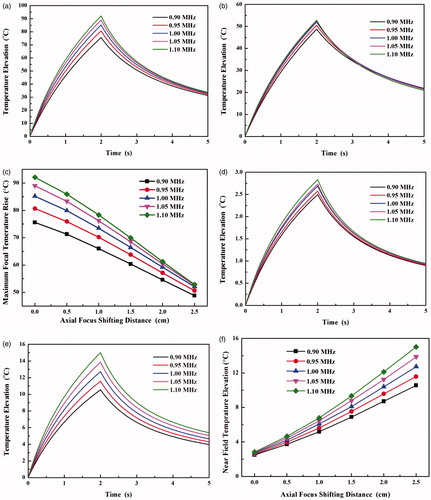
Figure 6. Axial distribution of the thermal dose with the axial focus shifting distance of (a) 0 cm and (b) 2.5 cm at the driving frequency from 0.9 MHz to 1.1 MHz and (c) comparison of the thermal dose at the grating lobe in the prefocal region with the axial focus shifting distance from 0 cm to 2.5 cm.
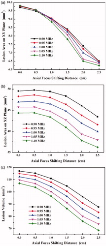
The lesion volume and focal area decrease with the axial focus shifting distance in a nonlinear manner, unlike the trend for the acoustic intensity (see . On average, the lesion area on the lateral plane (xy plane) reduces around 36%, and the frequency seems not to have a great impact on it. The relationship of the lesion area on the axial plane (xz plane) with the axial focus shifting distance is almost parallel to each other at all frequencies, decreasing by 12.4% at 0.9 MHz and by 18.4% at 1.1 MHz, respectively. In comparison, the high driving frequency has a great impact on the lesion volume, decreasing by 25.2% at 0.9 MHz and by 35.9% at 1.1 MHz for the axial focus shifted by 2.5 cm, respectively.
Figure 7. Comparison of the lesion area at the main lobe on (a) xy plane and (b) xz plane, and (c) the lesion volume with the various axial focus shifting distances from 0 cm to 2.5 cm and driving frequency from 0.9 MHz to 1.1 MHz.
Power compensation
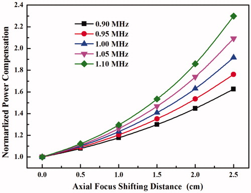
To retain a uniform lesion ablation, power compensation in the process of HIFU focus steering is always necessary to replenish the power loss. shows that the power compensation levels with respect to the geometrically focussing (non-steering case) increase exponentially with the axial focus shifting distance, and high frequency needs large power compensation. Shifting the HIFU focus axially for 2.5 cm needs about 63–130% more power in the compensation. However, as shown early that the pre-focal heating increases with the power applied to the HIFU transducer and the axial focus shifting distance, high power compensation results in high power accumulated in the near field. Consequently, more undesirable pre-focal heating would be produced. Therefore, there is another trade-off between the lesion uniformity and the near-field heating.
Figure 8. Power compensation at the various axial focus shifting distances from 0 cm to 2.5 cm and driving frequencies from 0.9 MHz to 1.1 MHz.
Prediction accuracy
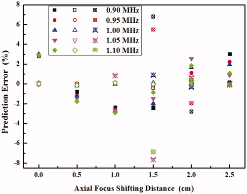
The characteristics of acoustic field, thermal field and produced lesion at the various axial focus shifting distances from 0 cm to 2.5 cm and driving frequencies from 0.9 MHz to 1.1 MHz can be predicted by simple models, such as the lesion volume at the focus and the position of grating lobe by a linear regression and the thermal dose at the grating lobe by an exponential growth regression, respectively. The corresponding prediction errors are shown in . It is found that the errors are quite satisfactory, usually within the range from −3% to 3%. The predictions for the other variables, such as acoustic intensity, temperature elevation and grating lobe level, are similar (data not included). The only exception is the thermal dose at the very weak grating lobe (e.g. prediction error >100% for less than 2D43). However, such a small thermal dose does not affect the thermal field or the production of the lesion significantly.
Figure 9. Prediction errors of the lesion volume at the focus (solid symbol) and the location of grating lobe (hollow symbol) using a linear model and the thermal dose at the grating lobe (hollow symbol with crosshair) at the various axial focus shifting distances from 0 cm to 2.5 cm and driving frequencies from 0.9 MHz to 1.1 MHz.
Discussion and conclusions
The hyperthermia and ablation by the phased array provide several advantages over the single-element transducer. The acceptable focus shifting distance is critical in both the transducer design and HIFU treatment planning. In this study, the acoustic intensity distribution of a 256-element phased array HIFU transducer through multiple layer tissues was first simulated using the established algorithm at the various axially post-focal shifting distances and driving frequencies [Citation18]. Then, the temperature elevation and thermal dose during HIFU exposure were determined. Most of the current simulations of acoustic field produced by phased-array are only based on the linear wave model because KZK model can only be applied to axially symmetric source at a moderate converging angle [Citation12,Citation18,Citation20]. In comparison to the prediction using the linear wave model, significantly higher acoustic intensity and temperature elevations were found. Variations of the grating lobe were calculated for the safety concern. Both the axially post-focal shifting distance and driving frequency affect the location, size and level of the grating lobe for the undesired tissue coagulation. Conventionally, steering the focus of a phased array is considered safe if the maximum intensity of grating lobe is −10 dB less than that of the focal intensity in the linear wave propagation [Citation7,Citation26]. Similar criterion, −10 dB as the optimal class and −7 dB as the suboptimal class, was used in evaluating the steering ability of random sparse arrays and aperiodic arrays [Citation27]. Since the nonlinearity of wave propagation is dependent on the acoustic pressure, the acoustic intensity at the focus increases significantly with the power applied while that of the grating lobe increases quasi-linearly. Therefore, absolute acoustic pressure, acoustic intensity and thermal dose of the grating lobe in the pre-focal region during the HIFU exposure instead of relative grating lobe levels should be considered for the production of irreversible necrosis. Quantitative determination of acoustic and thermal pattern of the grating lobe is critical. Although the grating lobe level is not significant at the small axial focus shifting distance, the temperature baseline will increase gradually because of the thermal diffusion effect [Citation28] during the HIFU ablation through the target volume which usually takes 1–3 h (median, 2.2 h) for breast cancer (size range from 2 to 4.8 cm in diameter, mean of 3.4 cm) with a margin of breast tissue of about 1.5–2.0 cm around the visible tumour in clinics [Citation29]. As a result, the produced lesion pattern which is dependent on the scanning pathway becomes larger with the progress of HIFU ablation [Citation28]. Thus, it is highly possible that the lesion in the pre-focal region does not appear at the beginning of HIFU ablation, but after some time.
The acoustic intensity of the main lobe decreases almost linearly with the axial focus shifting distance (Person’s correlation coefficient of −1, p < 10−6) while that of the grating lobe increases almost linearly (Person’s correlation coefficient of .997, p < 10−5). The maximum temperature rise in the near field during volumetric MR-HIFU ablation was found to correlate linearly with the surface energy density, which provides a priori safety check in an easy way [Citation30]. The quasi-linear relationship between the peak of acoustic intensity (at both main and grating lobe) and axial focus shifting distance would allow the clinician a quick and reliable evaluation of HIFU planning to avoid the excessive near-field temperature rise with the quite satisfactory prediction accuracies, but without the time-consuming numerical simulation whose accuracy may be comprised by the inhomogeneities and large variations in the physical properties of biological tissue and use is not conventionally adopted by clinical operators. At the different power outputs or transducer designs, the same regression models can be used to fit the coefficients. In addition, the energy loss due to the focus shifting is not because of the acoustic attenuation in the longer propagation distance, but due to the wide spread of acoustic energy (e.g. increased beam size). The ratio of the acoustic intensity of the electronically shifted beam to that of the mechanically moved beam for 1 cm post-focally is 89% (data not included), which means that the energy loss is not totally transferred to the grating lobe. Although the power compensation could ensure the same acoustic intensity delivered to the steered focal point, it is not preferred because of the significant grating lobe and subsequently near-field heating. The temperature elevation at the main lobe is high, and the thermal dose is beyond the threshold for tissue coagulation for HIFU ablation. The high temperature is also one of the reasons for HIFU-associated pains in the target. Treatment strategies for delivering the thermal dose just beyond the threshold in a short time with wide spreading, such as binary feedback control of heating time relying on rapid MR thermometry [Citation31] and minimising individual heating and inter-pulse cooling times while adhering to constraint limits of normal tissue at each sonication position [Citation32], are preferred.
The grating lobe level relies not only on the focus shifting distances but also on the configurations of phased array [Citation33]. Theoretically, phased array with element size less than half of the wavelength (< λ/2) will achieve the best grating lobe level because small elements are less directional and provide the better steering abilities [Citation34]. To meet such a criterion, the low frequency is preferred. Despite its high penetration depth, low acoustic attenuation, low threshold for acoustic cavitation and small grating lobe for the near-field heating, its shortcomings include the less significant effect of nonlinear acoustic wave propagation, the lower temperature elevation at the main lobe, and the larger beam size (both axial and lateral). However, fabrication of such small elements is very difficult even at the frequency of sub-MHz. Furthermore, the number of elements and subsequently, the cost and complexity in the assembly and control of each channel increases dramatically with the decreased element size despite the technical possibility. Formation of the grating lobes is also dependent on the element positions. Regular and periodic alignment results in a strong grating lobe and small steering of the beam [Citation27,Citation35]. The use of random or sparse-phased array can suppress the grating lobe, hence enhancing the steering ability [Citation12,Citation26]. But it is at the cost of high power output and large aperture size in order to maintain the similar output as the conventional design. Electronically steering of the randomised phased array also has the significant thermal dose deposited in the near-field region over mechanical steering of the same transducer [Citation36]. Because of the limited bandwidth of each HIFU transducer, the driving frequency can vary in a small range during the ablation. Subsequently, the location of grating lobe varies along the transducer axis, and the temperature elevation can be reduced by the spatial average effect, which has been confirmed in our experiment and will be reported soon.
If HIFU focus is shifted pre-focally towards the transducer, the grating lobe will appear in the post-focal region. Because of the high acoustic intensity at the focus in HIFU ablation, the negative pressure may be beyond the cavitation threshold to induce bubbles, which will shield the propagation of HIFU bursts in the post-focal region and scatter them towards the transducer. Therefore, the HIFU generated lesion changes its shape from cigar to tadpole with the large head moving gradually to the acoustic source when increasing the power applied to the transducer [Citation37]. The longer propagation distance in the tissue will also attenuate the acoustic wave further. Thus, it is reasonable that post-focal grating lobe is not serious as pre-focal one. Post-focal burning was seldom found unless the presence of high energy absorbing media, such as rib pain after HIFU treatment of breast cancer [Citation38]. The steering capability of phased array with single focus was investigated here. But it is not straightforward to assess the multiple foci as the superposition of several single focus cases. It has been shown that multiple foci synthesis has an inferior steering ability due to the increased grating lobe level by the acoustic wave interference [Citation18]. A comparison between the single-focus and multiple foci scans showed that multiple foci can considerably reduce the treatment duration but increase the pre-focal heating [Citation27,Citation35]. Therefore, great effort is required to reduce the grating lobe in the production of multiple foci by applying the appropriate apodization signals to each element.
In summary, the effect of axially post-focal shifting during the HIFU exposure has been assessed using the established algorithm which allows the simulation of nonlinear HIFU wave propagation from arbitrary excitation geometry through multiple tissue layers with different focussing strategies in an accurate and efficient way. Characteristics of both main and grating lobe could be determined quantitatively. The decrease of acoustic intensity of the main lobe, the increase in the grating lobe, the grating lobe level, and the shifting of grating lobe are all quasi-linearly related to the focus shifting distance, which allows easy estimation of the grating lobe for HIFU planning. Consequently, the temperature elevation at the main lobe, the lesion area and volume decreases with the shifting distance. High frequency always has high-temperature elevation and small lesion size at the main lobe, but the large decrease in the acoustic intensity with the focus shifting. In comparison, the thermal dose at the grating lobe could be large enough for tissue coagulation (240D43) when shifting the focus axially and post-focally. The criterion of −10 dB grating lobe level (acoustic intensity) to evaluate the safety of the steering ability may not be accurate, and the accumulated thermal dose using certain HIFU exposure scheme and scanning pathway is preferred in the evaluation. Prediction accuracies of the HIFU field characteristics using simple regression (e.g. the acoustic intensity, temperature elevation and lesion volume at the focus in a linear model, and the thermal dose at the grating lobe in an exponential growth model) based on the simulation data are satisfactory, which allows the easy and quick estimation of HIFU planning.
Disclosure statement
The authors report no conflicts of interest. The authors alone are responsible for the content and writing of the article.
References
- Zhou Y, Principles and applications of therapeutic ultrasound in health. Boca Raton (FL): CRC Press; 2015.
- Colen RR, Jolesz FA. (2010). Future potential of MRI-guided focused ultrasound brain surgery. Neuroimaging Clin N Am 20:355–66.
- Ebbini ES, Cain CA. (1989). Multiple-focus ultrasound phased-array pattern synthesis: optimal driving-signal distributions for hyperthermia. IEEE Trans Ultrason Ferroelectr Freq Control 36:540–8.
- Auboiroux V, Dumont E, Petrusca L, et al. (2011). An MR-compliant phased-array HIFU transducer with augmented steering range, dedicated to abdominal thermotherapy. Phys Med Biol 56:3563.
- Köhler MO, Mougenot C, Quesson B, et al. (2009). Volumetric HIFU ablation under 3D guidance of rapid MRI thermometry. Med Phys 36:3521–35.
- Wan H, VanBaren P, Ebbini ES, Cain CA. (1996). Ultrasound surgery: Comparison of strategies using phased array systems. IEEE Trans Ultrason Ferroelectr Freq Control 43:1085–98.
- Ebbini ES, Cain CA. (1991). A spherical-section ultrasound phased array applicator for deep localized hyperthermia. IEEE Trans Biomed Eng 38:634–43.
- Ji X, Bai J-f, Shen G-f, Chen Y-z. (2009). High-intensity focused ultrasound with large scale spherical phased array for the ablation of deep tumors. J Zhejiang Univ Sci B 10:639–47.
- Cain CA, Umemura S-I. (1986). Concentric-ring and sector-vortex phased-array applicators for ultrasound hyperthermia. IEEE Trans Microw Theory Tech 34:542–51.
- Ibbini M, Cain C. (1990). The concentric-ring array for ultrasound hyperthermia: combined mechanical and electrical scanning. Int J Hyperthermia 6:401–19.
- Ellens N, Pulkkinen A, Song J, Hynynen K. (2011). The utility of sparse 2D fully electronically steerable focused ultrasound phased arrays for thermal surgery: a simulation study. Phys Med Biol 56:4913.
- Hand J, Shaw A, Sadhoo N, et al. (2009). A random phased array device for delivery of high intensity focused ultrasound. Phys Med Biol 54:5675.
- Lu M, Wan M, Xu F, et al. (2005). Focused beam control for ultrasound surgery with spherical-section phased array: sound field calculation and genetic optimization algorithm. IEEE Trans Ultrason Ferroelectr Freq Control 52:1270–90.
- Jensen JA, Svendsen NB. (1992). Calculation of pressure fields from arbitrarily shaped, apodized, and excited ultrasound transducers. IEEE Trans Ultrason Ferroelectr Freq Control 39:262–7.
- Chen D, McGough RJ. (2008). A 2D fast near-field method for calculating near-field pressures generated by apodized rectangular pistons. J Acoust Soc Am 124:1526–37.
- Bailey M, Khokhlova V, Sapozhnikov O, et al. (2003). Physical mechanisms of the therapeutic effect of ultrasound (a review). Acoust Phys 49:369–88.
- Zhou Y, Zhai L, Simmons R, Zhong P. (2006). Measurement of high intensity focused ultrasound fields by a fiber optic probe hydrophone. J Acoust Soc Am 120:676.
- Wang M, Zhou Y. (2016). Simulation of non-linear acoustic field and thermal pattern of phased-array high-intensity focused ultrasound (HIFU). Int J Hyperthermia 25:691–9.
- Vyas U, Christensen D. (2012). Ultrasound beam simulations in inhomogeneous tissue geometries using the hybrid angular spectrum method. IEEE Trans Ultrason Ferroelectr Freq Control 59:1093–100.
- Yuldashev P, Khokhlova V. (2011). Simulation of three-dimensional nonlinear fields of ultrasound therapeutic arrays. Acoust Phys 57:334–43.
- Zemp RJ, Tavakkoli J, Cobbold RS. (2003). Modeling of nonlinear ultrasound propagation in tissue from array transducers. J Acoust Soc Am 113:139–52.
- Pennes HH. (1948). Analysis of tissue and arterial blood temperatures in the resting human foreman. J Appl Physiol 1:93–122.
- Sapareto S, Dewey W. (1984). Thermal dose determination in cancer therapy. Int J Radiat Oncol Biol Phys 10:787–800.
- Ginter S. (2000). Numerical simulation of ultrasound-thermotherapy combining nonlinear wave propagation with broadband soft-tissue absorption. Ultrasonics 37:693–6.
- Curra FP, Mourad PD, Khokhlova VA, et al. (2000). Numerical simulations of heating patterns and tissue temperature response due to high-intensity focused ultrasound. IEEE Trans Ultrason Ferroelectr Freq Control 47:1077–89.
- Goss SA, Frizzell LA, Kouzmanoff JT, et al. (1996). Sparse random ultrasound phased array for focal surgery. IEEE Trans Ultrason Ferroelectr Freq Control 43:1111–21.
- Gavrilov LR, Hand JW. (2000). A theoretical assessment of the relative performance of spherical phased arrays for ultrasound surgery. IEEE Trans Ultrason Ferroelectr Freq Control 47:125–39.
- Zhou Y, Kargl SG, Hwang JH. (2011). The effect of the scanning pathway in high-intensity focused ultrasound therapy on lesion production. Ultrasound Med Biol 37:1457–68.
- Wu F, Wang Z-B, Zhu H, et al. (2005). Extracorporeal high intensity focused ultrasound treatment for patients with breast cancer. Breast Cancer Res Treat 92:51–60.
- Mougenot C, Köhler M, Enholm J, et al. (2011). Quantification of near-field heating during volumetric MR-HIFU ablation. Med Phys 38:272–82.
- Enholm JK, Kohler MO, Quesson B, et al. (2010). Improved volumetric MR-HIFU ablation by robust binary feedback control. IEEE Trans Biomed Eng 57:103–13.
- Payne A, Vyas U, Blankespoor A, et al. (2010). Minimisation of HIFU pulse heating and interpulse cooling times. Int J Hyperthermia 26:198–208.
- Turnbull DH, Foster FS. (1991). Beam steering with pulsed two-dimensional transducer arrays. IEEE Trans Ultrason Ferroelectr Freq Control 38:320–33.
- Dolph C. (1946). A current distribution for broadside arrays which optimizes the relationship between beam width and side-lobe level. Proc IRE 34:335–48.
- Daum DR, Hynynen K. (1999). A 256-element ultrasonic phased array system for the treatment of large volumes of deep seated tissue. IEEE Trans Ultrason Ferroelectr Freq Control 46:1254–68.
- Payne A, Vyas U, Todd N, et al. (2011). The effect of electronically steering a phased array ultrasound transducer on near-field tissue heating. Med Phys 38:4971–81.
- Watkin N, Ter Haar G, Rivens I. (1996). The intensity dependence of the site of maximal energy deposition in focused ultrasound surgery. Ultrasound Med Biol 22:483–91.
- Li S, Wu P-H. (2013). Magnetic resonance image-guided versus ultrasound-guided high-intensity focused ultrasound in the treatment of breast cancer. Chin J Cancer 32:441–52.