
Abstract
Purpose: The thermal effect of the intramyocardial blood perfusion on the size of lesions created by radiofrequency cardiac ablation (RFCA) has not been adequately studied to date. Our objective was to assess the impact of including this phenomenon in RFCA computer modelling in terms of the thermal lesion depth created.
Methods: A computer model was built and computer simulations were conducted to assess the effect of including the blood perfusion term in the bioheat equation. This term mimics the intramyocardial blood flow (i.e., blood perfusion) in the cardiac wall at the site at which the RFCA is being conducted and hence represents a heat removing mechanism. When considered, blood perfusion rates ranged from 609 to 1719 ml/min/kg. Two electrode design and modes were considered: a non-irrigated electrode with constant temperature mode and an irrigated electrode with constant power mode.
Results: All the depths computed without including the blood perfusion term were larger than those that did include it, regardless of perfusion rate. The differences in lesion depth between ignoring and including blood perfusion increased over time; for a 60 s RFCA they were 0.45 and 1 mm for minimum and maximum perfusion rate, respectively. The differences were more or less independent of blood flow in the cardiac chamber, electrode type and ablation mode.
Conclusions: The findings suggest that the heat-sink effect of blood perfusion should be taken into account in the case of ablations (>1 minute) such as those conducted in RFCA of the ventricular wall.
Introduction
Radiofrequency (RF) ablation is a minimally invasive technique generally employed to cure cardiac arrhythmias. As with other high-temperature ablative techniques, numerical modelling has mostly been used to study the effect of different factors [Citation1], or even as a predictive tool to estimate the dimensions of the thermal lesion created [Citation2]. In mathematical terms, the problem is solved using the bioheat equation, which is a heat transfer equation generally used as a balance equation in heat transfer analysis. It includes a term to model the loss of heat by homogeneous blood flow in capillaries, that is, throughout the entire tissue. This mechanism of heat evacuation has been shown to be an important factor in limiting the size of the thermal lesion in certain circumstances, such as RF tumour ablation in well-perfused organs [Citation3] but has not been taken into account in RF cardiac ablation (RFCA). In this respect, since Haines and Watson [Citation4] reported that thermal lesion size was unaffected by the intramyocardial blood flow, most computer models have ignored the term of the bioheat equation representing blood perfusion [Citation5–14]. Only a couple of computer models considered this term [Citation15,16], with a perfusion value of 5 kg/m3 s, which is equivalent to 200 ml/min/kg. This value is much lower than that reported in data bases (average 1026 ml/min/kg; ranging from 609 to 1719 ml/min/kg) [Citation17]. Neither did these two computer studies assess the impact of its inclusion in the bioheat equation, that is, there was no comparison with the case without a blood perfusion term. The study by Obradovic et al. [Citation18] focussed on the thermal effect of the coronary artery flow by including its geometry in the model domain but did not consider the distributed thermal effect caused by the intramyocardial microvasculature, which is really modelled by the blood perfusion term of the bioheat equation. Interestingly, the Haines and Watson findings [Citation4] were exclusively based on constant temperature ablations conducted with a non-irrigated electrode. Consequently, the effect of the intramyocardial blood perfusion on lesion size under constant power and an irrigated electrode are still unknown. Our goal was thus to assess the impact of its inclusion in RF cardiac ablation computer models in terms of thermal lesion depth and to consider how information obtained from perfusion imaging techniques (e.g., those based on magnetic resonance imaging (MRI) [Citation19]) could be employed to tune computer-based predictive tools.
Materials and methods
Description of the computational model
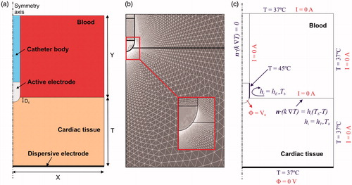
shows the geometry and dimensions of the computational model, which consists of a fragment of cardiac tissue and an electrode surrounded by circulating blood. The electrode was assumed to be placed in a perpendicular position with respect to the tissue in order to create an axis symmetry, which allowed us to consider a two-dimensional model. The electrode (7 Fr in diameter and 4 mm long) was assumed to be inserted into the tissue to a depth equal to one-sixth of its diameter (DE∼0.4 mm). Two electrode designs were considered, both similar to those currently used in RF cardiac ablation: a non-irrigated electrode and an irrigated electrode. The dispersive electrode was modelled as an electrical boundary condition at a distance from the active electrode (bottom surface). Cardiac tissue thickness (T) and the dimensions of blood chamber (X = Y) were estimated by means of a convergence test in order to avoid boundary effects. In this test, the control parameters were the value of the maximal temperature in the tissue (Tmax) and the lesion depth (D) at the axis symmetry, marked by the 50 °C isothermal line, after 60 s of RF heating. We first considered a tentative spatial (i.e., minimum meshing size) and temporal resolution. To determine the appropriate parameters, we increased their values by equal amounts. When the difference in the Tmax and D between consecutive simulations was less than 0.5%, we considered the former values to be adequate. We then determined adequate spatial resolution by means of a similar convergence test using the same control parameters as in the previous test. Discretisation was spatially heterogeneous: the finest zone was always the electrode–tissue interface, where the largest voltage gradient was produced and hence the maximum value of current density. In the tissue, grid size was increased gradually with distance from the electrode-tissue interface ().
Figure 1. (a) Geometry of the two-dimensional computational model built (not to scale). Dimensions of cardiac tissue and blood (X = Y = 40 mm) were obtained from a convergence test. Cardiac tissue thickness (T) was 40 mm. RF current flows between an active electrode (7 Fr, 4 mm) and the dispersive electrode (bottom). We considered two active electrode types: non-irrigated and irrigated. The active electrode is assumed to be inserted into cardiac tissue to a depth DE∼0.4 mm. (b) Detail of the mesh used in the model, showing a zoom of the zone with the finest grid size (interface electrode tissue). (c) Electrical and thermal boundary conditions of the model. hE and hT are the thermal convection coefficients at the electrode–blood and the tissue–blood interfaces, respectively. Only in the case of simulating an irrigated electrode, a constant temperature of 45 °C was applied at the electrode tip but not in the part inserted in the tissue.
Governing equations
The numerical models were based on a coupled electric–thermal problem, which was solved numerically using the finite-element method (FEM) with ANSYS software (ANSYS, Canonsburg, PA). Simulations were run on a Corel i7–3770 laptop with Windows 7 and 8 GB of RAM. The governing equation for the thermal problem was the bioheat EquationEquation (1)(1) :
(1)
where ρ is density (kg/m3), c specific heat (J/kg·K), T temperature (°C), t time (s), k thermal conductivity (W/mK), q the heat source caused by RF power (W/m3), Qp the heat loss caused by blood perfusion (W/m3) and Qm the metabolic heat generation (W/m3). Qm was not considered because it is negligible in comparison to the other terms [Citation5]. Qp was the most relevant term in the context of this study, and was computed as follows:
(2)
where ρb is the density of blood (kg/m3), cb the heat capacity of blood (J/Kg·K), Tb the blood temperature (37 °C), and ωb the blood perfusion coefficient (s−1). Three values of ωb for cardiac tissue were considered: ωb_min = 0.010 s−1, ωb_avg = 0.017 s−1, and ωb_max = 0.029 s−1 which corresponded with blood perfusion rates of 609, 1026 and 1719 ml/min/kg, respectively [Citation17]. These values were obtained from a database, which gathered data from two studies, and hence could be of limited worth. The most recent perfusion imaging techniques can assess the perfusion rate in specific zones of the cardiac muscle. For example, a recent study employed the arterial spin labelling (ASL) technique to measure blood perfusion in humans at rest and reported a value of 1750 ± 860 ml/min/kg, which is even higher than the maximum value reported in the above-mentioned database [Citation17]. The case without the blood perfusion term was also considered for comparison (ωb = 0). Furthermore, in all the cases, the value of ωb was set to zero at those points at which a temperature of 50 °C was reached, which allowed modelling the loss of blood perfusion due to the thermal destruction of the tissue.
At the RF frequencies (≈500 kHz) used in RF heating, and over the distance of interest, the biological medium can be considered almost totally resistive, since the displacement currents are much less important than the conduction currents. A quasi-static approach to solving the electrical problem was therefore possible [Citation20]. Then, the distributed heat source q is given by q = σ|E|2, where |E| is the magnitude of the vector electric field (V/m) and σ the electrical conductivity (S/m). E = –∇Ф is calculated from the gradient of the voltage Φ(V), which, in absence of internal electric sources, satisfies:
(3)
Model properties and boundary conditions
The thermal and electrical properties of the model elements are shown in [Citation15,Citation16]. The initial temperature in the entire model was 37 °C. The electrical (σ) and thermal conductivity of cardiac tissue was considered as a temperature-dependent function as follows: it rose linearly +1.6%/°C up to 100 °C, where 0.6 S/m was the value of the electrical conductivity assessed at 37 °C (), and then, it decreased two orders for five degrees to model the tissue desiccation process [Citation21].
Table 1. Physical characteristics of tissues and materials employed in the computational models (data from [Citation15,Citation16]).
shows the electrical and thermal boundary conditions. For the electrical boundary conditions, a Dirichlet voltage boundary condition was applied on the active electrode surface. As in clinical practice, two RF power delivery modes related to the electrode design were modelled: constant temperature mode with non-irrigated electrode and constant power mode with irrigated electrode. For the constant temperature mode, a proportional-integral (PI) control algorithm was implemented [Citation22] whose behaviour was determined by the proportional (Kp) and the integration (Ki) constant. The output of the PI controller corresponded to the applied voltage that was modulated to maintain the temperature at 50 °C in the sensor located approximately in the middle zone of the electrode tip [Citation23]. We adjusted Kp and Ki until achieving 50 °C in approximately 10 s, obtaining a value of Kp = 0.02 and Ki = 0.01. For constant power mode, the electrical current was adjusted by means of calculating the electrical impedance in order to apply a constant RF power of 8.5 W for 60 s. The applied power was set to zero if a temperature in the tissue ≥100 °C was reached at any time. All the outer surfaces of the model except the bottom surface were fixed at zero electric flux (Neumann boundary condition). The voltage on the bottom surface was set to 0 V (dispersive electrode) to mimic a monopolar configuration in which RF current was forced to flow between the active and dispersive electrodes.
Regarding the thermal boundary conditions, a null thermal flux was used on the symmetry axis and a constant temperature of 37 °C was fixed on the outer surfaces of the model at a distance from the ablating electrode (this was also the initial temperature value). The effect of blood circulating inside the cardiac chamber was modelled by thermal convection coefficients at the electrode–blood (hE) and the tissue–blood (hT) interfaces, considering electrical conductivity of blood independent of temperature (as in Method 2 in [Citation23]). Each coefficient was calculated under conditions of high and low blood flow. For this, we considered a value of hE = 3346 W/m2·K and hT = 610 W/m2·K for high blood flow, whereas a value of hE = 2059 W/m2·K and hT = 265 W/m2·K with low blood flow [Citation23]. The irrigated electrode was modelled by fixing a temperature of 45 °C only in the cylindrical zone of the electrode tip, leaving the semispherical tip free, as in a previous computational study [Citation24]. This approximation for modelling an irrigated electrode is suitable for predicting lesion depth and also the maximum temperature reached in the tissue at all times during ablation [Citation25].
Output variables
The lesion depths (D) computed without including the blood perfusion term in the bioheat equation were compared to those computed when it was included. The thermal lesion depths were identified by the 50 °C isotherm contour, as in previous studies [Citation6,Citation7,Citation11,Citation23], which is usually considered to reasonably represent the isotherm of irreversible myocardial injury in hyperthermic ablation [Citation26]. The applied total energy during was also calculated for each case.
Results
The convergence test provided optimal cardiac tissue thickness of T = 40 mm and blood chamber dimensions of X = Y = 40 mm, a grid size of ∼19 μm in the finest zone (electrode–tissue interface) and ∼2 mm in the coarser zone (outer limits). The asymmetrical model had around 16 200 elements and 9000 nodes. The time step was automatically set and was gradually increased from 2 to 200 ms.
shows the lesion depths and the applied total energy for each case. As expected, all the depths computed without including the blood perfusion term were larger than those that did include this term, regardless of the perfusion rate. When the depths computed without blood perfusion (ωb = 0) were compared with the case of average perfusion (ωb_max=0.017 s−1), the differences were ∼0.3 mm at 30 s and reached ∼0.7 mm after 60 s. The differences were more or less independent of the value of the thermal convection coefficient for high and low circulating blood flow, electrode type and ablation protocol. For the case of maximum perfusion (ωb_max=0.029 s−1, 1719 ml/min/kg), the differences increased by up to ∼1 mm after 60 s. shows the temperature distributions in the tissue after 30 and 60 s of radiofrequency ablation for this maximum rate. The increase in the difference over time is clearly noticeable. This case is relevant, since a recent study reported an even higher perfusion value for resting humans (1750 ± 860 ml/min/kg [Citation19]). shows the progress of applied power (between 6 and 7 W) in the case of constant power ablation, and electrode temperature (50 °C target) in the case of constant temperature ablation.
Figure 2. Temperature distributions in the tissue after 30 and 60 s of radiofrequency ablation with (a) a non-irrigated electrode at constant temperature and (b) with an irrigated electrode at constant temperature. Plots correspond to cases in which the blood perfusion term was not included in the bioheat equation. Solid line is the 50 °C isotherm, which can be assumed to be the thermal lesion contour. Dashed line represents the location of this contour when the blood perfusion term is included at a rate of 1719 ml/min/kg (maximum value reported in [Citation17], but very similar to that measured in resting humans (1750 ± 860 ml/min/kg) using perfusion imaging techniques [Citation19]).
![Figure 2. Temperature distributions in the tissue after 30 and 60 s of radiofrequency ablation with (a) a non-irrigated electrode at constant temperature and (b) with an irrigated electrode at constant temperature. Plots correspond to cases in which the blood perfusion term was not included in the bioheat equation. Solid line is the 50 °C isotherm, which can be assumed to be the thermal lesion contour. Dashed line represents the location of this contour when the blood perfusion term is included at a rate of 1719 ml/min/kg (maximum value reported in [Citation17], but very similar to that measured in resting humans (1750 ± 860 ml/min/kg) using perfusion imaging techniques [Citation19]).](/cms/asset/f594b63d-3a3a-4f6b-bc17-197689616f1a/ihyt_a_1336258_f0002_c.jpg)
Figure 3. Progress of applied power (between 6 and 7 W) in the case of constant power ablation and electrode temperature (50 °C target) in the case of constant temperature ablation.
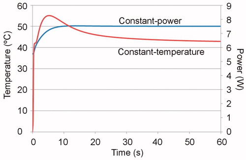
Table 2. Thermal lesion depths (in mm) computed for the cases with and without blood perfusion term at 30 and 60 s. The applied total energy for each case is reported in brackets.
The applied total energy required to keep the temperature constant with the non-irrigated electrode was highly dependent on the blood flow around the electrode and on the tissue surface (parameters hE and hT) but was practically unaffected by the intramyocardial capillary blood flow (term Qp). Logically, in the case of the irrigated electrode with constant power, the applied total energy was constant in all cases.
Discussion
This study employed a numerical model to assess the thermal effect of intramyocardial capillary blood flow on the lesion depth created after RFCA. Overall, the values of the lesion depths computed were similar to those reported in experimental studies [Citation4]. The computer simulations showed that the fact of including or ignoring the blood perfusion term (with a perfusion rate of 1719 ml/min/kg) could imply a difference of up to ∼1 mm after 60 s of RFCA, both with irrigated and with non-irrigated electrodes. Although this value is comparable to the standard deviation usually reported for the experimentally obtained lesion depths [Citation4], the result has important implications from both the modelling and clinical points of view. As regards RFCA modelling, our results suggest that the Qp term should be taken into account for models with application times longer than 60 s. The clinical implication is evident: under certain circumstances, intramyocardial capillary blood flow could limit the growth of the lesion created during RFCA, impeding it from reaching the target causing the arrhythmia.
Comparison with experimental data
To our knowledge, the only extant experimental data on the effect of blood perfusion in RFCA is that of the study carried out by Haines and Watson [Citation4]. Although these authors did not observe any differences in lesion depth between the perfusion and non-perfusion group, we suspect that their experimental conditions did not accurately reproduce in vivo conditions in terms of intramyocardial blood perfusion. Both in [Citation4] and in a subsequent study published a year later [Citation27] the myocardial perfusion was maintained by infusing a solution through a coronary artery at 10 ml/min. Interestingly, this value is lower than some reported ranges (18–161 ml/min [Citation28], 56–113 ml/min [Citation29]), which could be why they found no differences between thermal lesions created with and without perfusion.
Although the available experimental data on the effects of blood perfusion on RFCA lesion size are scarce, the present findings could also be considered in the context of RF ablation on other organs, for instance the liver, in which hepatic vascular inflow occlusion during RF ablation (Pringle maneuver) is a feasible method of drastically increasing lesion volume [Citation30], which suggests that blood perfusion is indeed relevant in this case. Surprisingly, the database employed in this study [Citation17] provides smaller blood perfusion values for liver (average of 860 ml/min/kg, range 422–1273 ml/min/kg) than for heart muscle (average of 1026 ml/min/kg, range 609–1719 ml/min/kg), which suggests that if it is relevant for liver ablation, it should also be important in cardiac ablation.
Clinical and experimental implications
The results of the present study show that the effect of the blood perfusion term increases in importance as ablation progresses, which suggests that the possible clinical implications should distinguish between short- and long-duration cardiac ablations. The maximum difference between including and excluding blood perfusion (∼1 mm after 60 s) is probably irrelevant in the case of RFCA for atrial fibrillation, in which the aim is to create transmural lesions on an atrial wall that may be as thin as 0.6 – 1.0 mm [Citation31], even though the intramyocardial capillary blood flow is increased in this case [Citation32]. More important is the fact that ablations on the atrial wall are getting shorter and shorter, so that, for instance, we can affirm that the blood perfusion effect will be completely negligible for ultra-short applications of just 5 s [Citation33].
The implications will be different in the case of RFCA for scar-mediated ventricular tachycardia, in which the tissue area responsible for the arrhythmia (i.e., the target) could be situated deep in the ventricular wall, which would require a thermal lesion deep enough to destroy the focus of the arrhythmia. In fact, the current ablative technologies are sometimes unable to create thermal lesions deep enough to reach the target. To overcome this drawback, ablations are generally longer than 1 min [Citation34] with the idea of getting the lesion to grow by thermal conduction. Moreover, as in RF hepatic ablation clamping manoeuvres, our results indirectly suggest that some kind of occlusion aimed at temporarily ceasing intramyocardial blood perfusion (and hence cancelling the Qp term) could be employed in the presence of thick ventricular walls (where the target is expected to be quite deep) in order to minimise the heat removal effect and to obtain larger lesions. In fact, this strategy has already been used in the past in cardiac ablations next to the coronary venous system in order to minimise its heat-sink effect [Citation35].
The present results suggest that, at least in long ablations, the intra-myocardial blood perfusion term should be taken into account in the context of developing computer modelling tools to guide RFCA therapies. In practical terms, this could be done by measuring the blood perfusion at the specific target point (picked up for instance by magnetic resonance imaging). Other pretreatment measurements could be conducted to characterise the tissue properties in the target zone and hence to improve the accuracy of simulation-based tools. For instance, impedance measurements would make it possible to estimate electrical conductivity. In this respect, previous results have shown that the changes in specific heat and electrical and thermal conductivities from +100% to –50% implied lesion depths that ranged from 0.5 to 2.2 mm [Citation9]. Some of these figures are indeed comparable with the differences found in the present study between ignoring and including the blood perfusion term, which once again suggests that the effects of this term need not be considered.
Although the effect of ignoring/including the blood perfusion term was more or less independent of the blood flow around the ablation electrode (see last column in ), the specific value of the convective heat transfer coefficient (which depends on the ablation site [Citation2,Citation11]) did have an important effect on lesion depth (differences up to 1 mm between high and low blood flow). Consequently, in order to develop computer modelling-based tools able to predict lesion size, pre-treatment clinical measurements could be conducted to assess local blood flow conditions, for instance by applying low-power pulses prior to ablation and observing the temperature evolution measured by a sensor embedded at the catheter tip [Citation36,Citation37].
Limitations of the study
This study has certain limitations that need to be pointed out. Firstly, the model assumed homogeneous tissue in terms of all tissue properties, including blood perfusion. The results could thus vary if the model assumed the spatial heterogeneity of blood perfusion, for example within a target zone causing cardiac arrhythmia. However, if realistic information about this spatial distribution could be obtained by perfusion imaging techniques, it could be subsequently used in the model to increase its accuracy.
Secondly, the value of ωb was set to zero at those points at which a temperature of 50 °C was reached. Although this method of mimicking the cessation of perfusion caused by thermal necrosis has commonly been employed in thermal ablation models [Citation38,Citation39], it may not be sufficient, as it does not consider the exponential time–temperature relationship of microvascular perfusion cessation [Citation40]. Schutt and Haemmerich [Citation40] compared the method based on a threshold temperature (as employed in this study) to another in which cessation was gradual and dependent on a thermal damage function. They simulated ablations of 12–15 min, which is considerably longer than those simulated here (1 min). It is possible that the differences are much smaller in the case of short ablations.
Thirdly, all the computer simulations were conducted for a specific set of tissue properties. However, we can assume that the effect of changing the tissue properties is reasonably independent of the blood perfusion effect, as this mechanism basically acts as a heat evacuator in the governing equation [Citation41]. Furthermore, previous simulations of RF hepatic ablation considering applications several minutes long showed that the inclusion of the blood perfusion term has an even greater impact on lesion size than variations in the electrical conductivity of the tissue [Citation42].
Fourthly, the models built included the thermal effect of circulating blood inside the cardiac chamber by considering convective coefficients at the electrode–blood and tissue–blood interfaces. For this purpose, the models included the blood in the domain and assumed a constant value for its electrical conductivity. This method is the most suitable alternative to including the blood circulation in order to reduce the computational complexity [Citation23], and although it does not provide a realistic blood temperature distribution, it does predict lesion depth reasonably well. The maximum differences found in our study between including and excluding the blood perfusion term were around 1 mm, which could suggest that the method employed was not suitable. In spite of this, since the effect of the blood perfusion term is simply to evacuate heat evenly and in proportion to the local temperature rise (EquationEquation (2)(2) ), we can assume that the conclusions would be equally valid in the case of 3 D models including blood circulation.
And finally, the conclusions drawn here have to do only with the blood perfusion term associated with capillary myocardial perfusion. The proximity of large vessels such as the great cardiac vein and coronary sinus would surely have a great impact in terms of heat evacuation and hence would limit the lesion size [Citation35]. Computer modelling of RFA next to these large vessels should explicitly include the geometry of the vessel, as in Obradovic et al [Citation18]. In these cases, extra energy will possibly have to be delivered in order to overcome the protective thermal effect of vascular perfusion [Citation43], as opposed to the only 1 J of extra energy that had to be applied in the constant temperature case in the present study.
Conclusions
The results show that the lesion depths computed by including the blood perfusion term could be up to 1 mm larger than those computed by ignoring this effect in the case of long ablations (>1 min). As a result, our findings suggest that blood perfusion should be taken into account in long ablations on the ventricular wall, while it can be ignored for short ablations on the atrial wall.
Disclosure statement
The authors have no conflicts of interest or financial disclosures to make relevant to this submission.
Additional information
Funding
References
- Berjano EJ. (2006). Theoretical modeling for radiofrequency ablation: state-of-the-art and challenges for the future. Biomed Eng Online 5:24.
- Lai YC, Choy YB, Haemmerich D, et al. (2004). Lesion size estimator of cardiac radiofrequency ablation at different common locations with different tip temperatures. IEEE Trans Biomed Eng 51:1859–64.
- Poch FG, Rieder C, Ballhausen H, et al. (2016). The vascular cooling effect in hepatic multipolar radiofrequency ablation leads to incomplete ablation ex vivo. Int J Hyperthermia 32:749–56.
- Haines DE, Watson DD. (1989). Tissue heating during radiofrequency catheter ablation: a thermodynamic model and observations in isolated perfused and superfused canine right ventricular free wall. Pacing Clin Electrophysiol 12:962–76.
- Labonté S. (1994). Numerical model for radio-frequency ablation of the endocardium and its experimental validation. IEEE Trans Biomed Eng 41:108–15.
- Panescu D, Whayne JG, Fleischman SD, et al. (1995). Three-dimensional finite element analysis of current density and temperature distributions during radio-frequency ablation. IEEE Trans Biomed Eng 42:879–90.
- Jain MK, Wolf PD. (1999). Temperature-controlled and constant-power radio-frequency ablation: what affects lesion growth? IEEE Trans Biomed Eng 46:1405–12.
- Jain MK, Wolf PD. (2000). A three-dimensional finite element model of radiofrequency ablation with blood flow and its experimental validation. Ann Biomed Eng 28:1075–84.
- Tungjitkusolmun S, Woo EJ, Cao H, et al. (2000). Thermal–electrical finite element modelling for radio frequency cardiac ablation: effects of changes in myocardial properties. Med Biol Eng Comput 38:562–8.
- Tungjitkusolmun S, Woo EJ, Cao H, et al. (2000). Finite element analyses of uniform current density electrodes for radio-frequency cardiac ablation. IEEE Trans Biomed Eng 47:32–40.
- Tungjitkusolmun S, Vorperian VR, Bhavaraju N, et al. (2001). Guidelines for predicting lesion size at common endocardial locations during radio-frequency ablation. IEEE Trans Biomed Eng 48:194–201.
- Cao H, Vorperian VR, Tungjitkusolmun S, et al. (2001). Flow effect on lesion formation in RF cardiac catheter ablation. IEEE Trans Biomed Eng 48:425–33.
- Gallagher N, Fear EC, Byrd IA, Vigmond EJ. (2013). Contact geometry affects lesion formation in radio-frequency cardiac catheter ablation. PLoS One 8:e73242.
- Wright M, Harks E, Deladi S, et al. (2011). Real-time lesion assessment using a novel combined ultrasound and radiofrequency ablation catheter. Heart Rhythm 8:30412.
- Shahidi AV, Savard P. (1994). A finite element model for radiofrequency ablation of the myocardium. IEEE Trans Biomed Eng 41:963–8.
- Consiglieri L. (2013). An analytical solution for a bio-heat transfer problem. Int J Bio-Sci Bio-Technol 5:267–78.
- Hasgall PA, Di Gennaro F, Baumgartner C, et al. “IT’IS Database for thermal and electromagnetic parameters of biological tissues,” Version 3.0, 1 September 2015, doi: 10.13099/VIP21000-03-0. Available from: www.itis.ethz.ch/database [last accessed 21 April 2017].
- Obradović M, Avilla A, Thiagalingam A, Filipović N. (2010). Finite element modeling of the endocardial radiofrequency ablation. J Serbian Soc Computational Mechanics 4:43–53.
- Yoon AJ, Do HP, Cen S, et al. (2017). Assessment of segmental myocardial blood flow and myocardial perfusion reserve by adenosine-stress myocardial arterial spin labeling perfusion imaging. J Magn Reson Imaging. [Epub ahead of print]. doi: 10.1002/jmri.25604.
- Doss JD. (1982). Calculation of electric fields in conductive media. Med Phys 9:566–73.
- Byeongman J, Aksan A. (2010). Prediction of the extent of thermal damage in the cornea during conductive thermokeratoplasty. J Therm Biol 35:167–74.
- Haemmerich D, Webster JG. (2005). Automatic control of finite element models for temperature-controlled radiofrequency ablation. Biomed Eng 4:42.
- González-Suárez A, Berjano E. (2016). Comparative analysis of different methods of modeling the thermal effect of circulating blood flow during RF cardiac ablation. IEEE Trans Biomed Eng 63:250–9.
- Pérez JJ, D’Avila A, Aryana A, Berjano E. (2015). Electrical and thermal effects of esophageal temperature probes on radiofrequency catheter ablation of atrial fibrillation: results from a computational modeling study. J Cardiovasc Electrophysiol 26:556–64.
- González-Suárez A, Pérez JJ, Berjano E. (2017). Approximate method of modeling irrigated-tip electrodes during RF cardiac ablation: comparative analysis versus an accurate method including blood motion and saline flow interaction. Int J Hyperth (under review).
- Haines DE. (2011). Letter by Haines regarding article. Direct measurement of the lethal isotherm for radiofrequency ablation of myocardial tissue. Circ Arrhythm Electrophysiol 4:e67.
- Haines DE, Watson DD, Verow AF. (1990). Electrode radius predicts lesion radius during radiofrequency energy heating. Validation of a proposed thermodynamic model. Circ Res 67:124–9.
- Hundley WG, Lange RA, Clarke GD, et al. (1996). Assessment of coronary arterial flow and flow reserve in humans with magnetic resonance imaging. Circulation 93:1502–8.
- Takahashi S, Coskun AU, Papafaklis MI, et al. (2013). Relation of distribution of coronary blood flow volume to coronary artery dominance. Am J Cardiol 111:1420–4.
- Park MH, Cho JS, Shin BS, et al. (2012). Comparison of internally cooled wet electrode and hepatic vascular inflow occlusion method for hepatic radiofrequency ablation. Gut Liver 6:471–5.
- Bishop M, Rajani R, Plank G, et al. (2016). Three-dimensional atrial wall thickness maps to inform catheter ablation procedures for atrial fibrillation. Europace 18:376–83.
- White CW, Holida MD, Marcus ML. (1986). Effects of acute atrial fibrillation on the vasodilator reserve of the canine atrium. Cardiovasc Res 20:683–9.
- Bhaskaran A, Chik W, Pouliopoulos J, et al. (2017). Five seconds of 50-60 W radio frequency atrial ablations were transmural and safe: an in vitro mechanistic assessment and force-controlled in vivo validation. Europace 19:874–80.
- Bhaskaran A, Nalliah C, Chik W, et al. (2016). Ninety seconds could be the optimal duration for ventricular radiofrequency ablation – results from a myocardial phantom model. Heart Lung Circ 9506:31484–6.
- D'Avila A, Thiagalingam A, Foley L, et al. (2008). Temporary occlusion of the great cardiac vein and coronary sinus to facilitate radiofrequency catheter ablation of the mitral isthmus. J Cardiovasc Electrophysiol 19:645–50.
- Schumacher B, Eick O, Wittkampf F, et al. (1999). Temperature response following nontraumatic low power radiofrequency application. Pacing Clin Electrophysiol 22:339–43.
- dos Santos I, Will JA, da Rocha AF, et al. (2003). In vivo measurements of heat transfer on the endocardial surface. Physiol Meas 24:793–804.
- Lobo SM, Liu ZJ, Yu NC, et al. (2005). RF tumour ablation: computer simulation and mathematical modelling of the effects of electrical and thermal conductivity. Int J Hyperthermia 21:199–213.
- Liu Z, Ahmed M, Sabir A, et al. (2007). Computer modeling of the effect of perfusion on heating patterns in radiofrequency tumor ablation. Int J Hyperthermia 23:49–58.
- Schutt DJ, Haemmerich D. (2008). Effects of variation in perfusion rates and of perfusion models in computational models of radio frequency tumor ablation. Med Phys 35:3462–70.
- Chang IA, Nguyen UD. (2004). Thermal modeling of lesion growth with radiofrequency ablation devices. Biomed Eng Online 3:27.
- Chang I. (2003). Finite element analysis of hepatic radiofrequency ablation probes using temperature-dependent electrical conductivity. Biomed Eng Online 2:12.
- Fuller IA, Wood MA. (2003). Intramural coronary vasculature prevents transmural radiofrequency lesion formation: implications for linear ablation. Circulation 107:1797–803.