
Abstract
Purpose: Currently available hyperthermia technology is not well suited to treating cancer malignancies in the intact breast. This study investigates a microwave applicator incorporating multiple patch antennas, with the goal of facilitating controllable power deposition profiles for treating lesions at diverse locations within the intact breast.
Materials and methods: A 3D-computational model was implemented to assess power deposition profiles with 915 MHz applicators incorporating a hemispheric groundplane and configurations of 2, 4, 8, 12, 16 and 20 antennas. Hemispheric breast models of 90 mm and 150 mm diameter were considered, where cuboid target volumes of 10 mm edge length (1 cm3) and 30 mm edge length (27 cm3) were positioned at the centre of the breast, and also located 15 mm from the chest wall. The average power absorption (αPA) ratio expressed as the ratio of the PA in the target volume and in the full breast was evaluated. A 4-antenna proof-of-concept array was fabricated and experimentally evaluated.
Results: Computational models identified an optimal inter-antenna spacing of 22.5° along the applicator circumference. Applicators with 8 and 12 antennas excited with constant phase presented the highest αPA at centrally located and deep-seated targets, respectively. Experimental measurements with a 4-antenna proof-of-concept array illustrated the potential for electrically steering power deposition profiles by adjusting the relative phase of the signal at antenna inputs.
Conclusions: Computational models and experimental results suggest that the proposed applicator may have potential for delivering conformal thermal therapy in the intact breast.
Introduction
Breast cancer is the most frequent cancer among women; in 2013, breast cancer accounted for 29% of all new female cancer diagnoses in the United States [Citation1]. Early detection is crucial in the control of the disease [Citation2], with the rationale that if the tumour is detected when it is still entirely localised within the breast, complete excision through mastectomy or lumpectomy may be curative [Citation3]. Lumpectomy (or breast-conserving surgery) is a standard treatment alternative to mastectomy (or total removal of a breast) for some patients with tumours in the size of 4 cm or less [Citation4,Citation5]. In many occasions, lumpectomy or mastectomy is preceded or followed by radiotherapy and/or chemotherapy [Citation4]. Clinical microwave hyperthermia, moderate heating in the range of 39–44 °C for 30–90 min, has been clinically proven as a potential adjuvant to radiotherapy and/or chemotherapy for various cancers [Citation6–10]. Specifically, for superficial breast cancer and chest wall recurrence or recurrence in the chest wall, clinical trials combining radiotherapy and hyperthermia have shown significant improvement in complete response [Citation11,Citation12]. Hyperthermia is also under investigation for thermally triggered release of cancer therapeutic agents in various targets, including the breast [Citation13], to enhance the immune response [Citation14], and combined with nanoparticles [Citation15].
While a large proportion of tumours arise in the upper outer quadrant of the breast [Citation16,Citation17], breast carcinomas can develop in any location of the breast [Citation18]. Clinical hyperthermia applicators should have the ability to steer energy deposition to targets of varying size and shape that may be found at diverse locations within the breast. Commercially available clinical applicators for hyperthermia treatment of superficial chest wall disease mostly employ waveguides [Citation19]. While these systems are relatively easy to use, they are large and bulky and thereby resulting in patient discomfort and limited power steering. Focused ultrasound (FUS) applicators have been developed for hyperthermia and thermal ablation of deep-seated breast targets [Citation20]. An advantage of FUS systems is that the small acoustic wavelength (∼mm) affords precise focussing of energy delivery to targets. Microwave applicators [Citation21] offer the advantage of heating broader volumes without requiring complex control strategies as needed with FUS.
Although single antenna applicators offer the advantage of simplified practical implementation and treatment delivery, they are limited in spatial control of energy deposition patterns. Systems incorporating multiple antennas facilitate electronic steering of power deposition within the breast. The focussing may be achieved through simultaneous operation of multiple antenna applicators as a phased array [Citation21–25], or by sequentially activating individual antennas [Citation26], and they can be broadly classified into narrowband systems (i.e. operating at a fixed frequency) [Citation27–32] or ultra-wideband systems [Citation33–36]. When operated as a phased array, the amplitude and relative phase of the signal supplied to each antenna can be adjusted to yield constructive interference in a desired region (target), and destructive interference elsewhere (non-target tissues).
We have recently presented a 915 MHz single patch antenna with a conformal groundplane for delivering microwave hyperthermia to targets in the intact breast [Citation37]. The objective of this study was to design and characterise the technical efficacy of a 915 MHz phased array applicator comprised multiple patch antennas and a shared groundplane, in order to develop a comfortable and wearable hyperthermia system and to deliver hyperthermia to tumours positioned at varying breast locations. To account for diversity in breast dimensions, two 3D-hemispherical breast models with diameter of 90 mm and 150 mm were considered in this study. We evaluated cuboid target tumours with maximum edge lengths of 10 mm (1 cm3) and 30 mm (27 cm3), as representative of small and large targets, respectively. We investigated tumour targets centred at the midline of the breast, near the chest wall, and laterally positioned. Applicator designs were comparatively assessed by evaluating power deposited in a targeted area normalised to the total power deposited in the full breast. To validate our simulation approach, a proof-of-concept multi-antenna applicator was fabricated and induced transient temperature profiles were measured in tissue phantoms of ex vivo chicken breast.
Materials and methods
Numerical breast phantom
Optimal configuration of a microwave hyperthermia breast applicator is a function of biophysical (perfusion and dielectric parameters) and dimensional (breast size and composition, and tumour location) parameters that may vary considerably amongst individual patients. Thus, practical systems must trade-off the optimal treatment of selected patient populations with the ability to adequately treat a wide variety of patients. To account for diversity in breast dimensions, two numerical breast phantoms have been evaluated. The phantoms are hemispheric models of outer diameter 90 mm (small breast model) and 150 mm (large breast model) and both are made of a 2 mm-thick skin layer encompassing fibroglandular tissue [Citation37,Citation38]. The chest wall was modelled as a rectangular layer of 170 mm edge for the small breast model and 230 mm edge for the large breast model of 15 mm-thick fat and 5 mm-thick muscle [Citation37,Citation39] as shown in . Frequency-dependent dielectric properties for water, skin, fibroglandular, fat and muscle tissue were implemented in the model, as listed in .
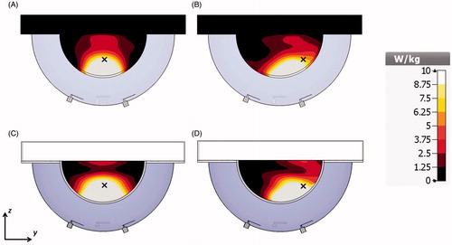
Figure 1. 2-antenna array applicator with small breast model with target located in the breast centre (A) and near the chest wall (B) and large breast model with target located in the breast centre (C) and near the chest wall (D).
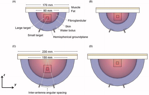
Table 1. Tissue dielectric properties for 915 MHz.
Cuboid target volumes of 10 mm edge length (1 cm3) and 30 mm edge length (27 cm3) located in the midline of the breast centre and also near the chest wall were evaluated (see ). The centrally located tumour targets () were positioned with their centre at 22.5 mm and 37.5 mm from the skin in the case of the small and large breast models, respectively. The tumours located near the chest wall () were positioned with their centre at 15 mm from the fat layer of the chest wall.
Antenna geometry
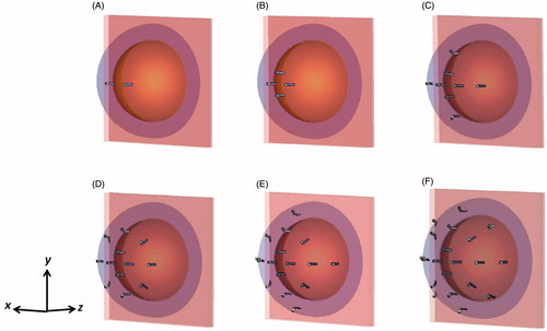
Array configurations with 2, 4, 8, 12, 16 and 20 patch antennas operating at 915 MHz were evaluated. All the antennas shared a hemispherical groundplane concentric to the breast target. The diameter of the hemispherical groundplane was 147 mm for array configurations for the small breast model and 207 mm for array configurations for the large breast model, which corresponds to a 25 mm patch antenna–breast distance. The 14 mm × 3.9 mm rectangular patch antennas with groundplane to patch distance of 2.65 mm were designed following the description of the single antenna presented in previous research [Citation37]. The distance between the patches and the breast was fixed to 25 mm for all the array configurations, since preliminary investigations showed that this value presented a compromise between power absorption (PA) as well as wearability and comfort of the applicator considering that thinner and consequently lighter water boluses will improve patient comfort [Citation43]. The water bolus formed the cavity enclosed by the hemispherical groundplane, breast and chest wall. Deionised water, completely filling the water bolus, was used to improve impedance matching, reduce the size of the applicator and cool both the antenna and surface of the skin [Citation37].
The antennas were positioned on the applicator circumference along orthogonal arcs (the x-axis and the y-axis) and located in the diagonal between the x-axis and y-axis as depicted in . Antenna distribution along the orthogonal arcs was previously proposed by Bahramiabarghouei et al. [Citation44]. All patch antennas were located at the constant distance defined by the parameter of inter-antenna angular spacing shown in . This parameter was analysed to obtain the greatest PA in the desired target without compromising the impedance matching of individual antennas. A maximum acceptable value of S11 for each antenna element (including coupling with other elements) was set to −8.5 dB. Larger spacing between antennas decreases the ability to focus energy, while the smaller inter-antenna spacing generates near-field interferences that would compromise the impedance matching of the system. Smaller inter-antenna angular spacing allows the implementation of a larger number of antennas with the potential for good control of steerable power deposition profiles, at the expense of increased system complexity.
Figure 2. 3D view of array configurations with 2 (A), 4 (B), 8 (C), 12 (D), 16 (E) and 20 (F) antennas positioned on the applicator circumference along orthogonal arcs (the x-axis, the y-axis) and located in the diagonal between the x-axis and y-axis.
Evaluation of proposed designs
The PA was evaluated in the target volumes and in the full breast volume using EquationEquation 1(1) [Citation45,Citation46].
(1) where σ is the effective electrical conductivity of the tissue in S/m and |E| is the complex electric field (E-field) vector in V/m. The system performance is expressed in terms of the αPA ratio as defined in EquationEquation 2
(2) .
(2) where PAtarg is the power absorbed in the target volume, targ_volume is the volume of the target, PAbreast is the power absorbed in the entire breast volume, and breast_volume is the cubic volume that encloses the breast.
Phase adjustment to steer power deposition profiles
The objective function described in Wu et al. [Citation29] was employed to determine the optimal phases of the signal applied to each antenna that results in E-field maximisation at points within the tumour. The total E-field in the tumour centre was defined as superposition of the individual E-field of N antennas, and computed as in EquationEquation 3(3) ;
(3) where Un is the E-field produced by the nth antenna with unit input excitation and In is a complex number that represents the amplitude and the phase of the nth antenna. A focus is generated when the individual E-field components constructively interfere at a defined location, and the highest interference is achieved when the magnitude squared of the total E-field is maximised relative to the sum of the squared input magnitudes as in EquationEquation 4
(4) [Citation29].
(4)
When the amplitude of the antenna inputs is defined in advance, EquationEquation (4)(4) is a nonlinear function with the antenna input phases as variables [Citation29]. Then, the magnitude squared of the total E-field in the tumour region can be obtained as a nonlinear objective function as shown in EquationEquation 5
(5) ;
(5) where θn and θm are the arguments of the E-field Un and Um, respectively, and øn and øm are the phases of the excitations In and Im, respectively. The reference phase of the N element is set to øN = 0°. We first computed the E-field of each antenna independently and we specified constant magnitude of the excitations with the electromagnetic simulation. The technique used to solve the optimisation problem was the iterative Nelder–Mead simplex algorithm [Citation47]. Maximising the objective function the algorithm generates the phases øn that produce a constructive E-field interference in the tumour region. The termination criterion for the algorithm was a tolerance of 1 × 10⁻⁸ between iterations.
Electromagnetic simulations were performed using CST Microwave Studio [Citation48] on a 3.0 GHz PC with 16 GB RAM. Memory requirements and simulation times ranged from 691 MB and ∼40 min for the small breast model with the 2-antenna array configuration to 13 GB and ∼8 h for the large breast model with the 20-antenna array configuration. Phased array computations were performed using Matlab (R2015).
Experimental evaluation and validation
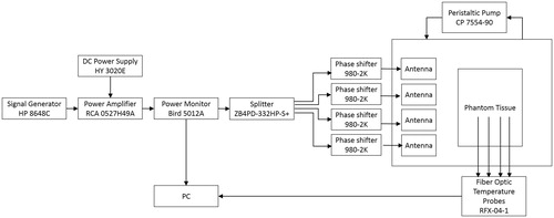
A 4-antenna array configuration with inter-antenna angular spacing of 45° and hemispherical groundplane was fabricated for experimental evaluation in a small breast model. The patches and groundplane were implemented with 0.127 mm-thick copper sheets (McMaster-Carr, Elmhurst, IL) and the antennas were fed with 50 Ω SMA female connectors (PE4099, Pasternack Enterprise, Irvine, CA). shows a photograph of the fabricated applicator showing the 4-antenna array configuration. The broadband reflection coefficient of the 4-antennas was measured when loaded with a tissue phantom of ex vivo chicken breast. Tissue samples were stored in a refrigerator at a temperature of ∼4 °C. Before performing the heating experiments, the sample was enclosed in sealed bags and heated up to 32 °C in a controlled bath. Just before performing the experiment, the samples were removed from the plastic bags and positioned in a 3D-printed 1.5 mm-thick PTFE fixture to perform the heating experiments. shows a photograph of the 3 D-printed fixture. Fiber-optic temperature probes (Neoptix RFX-04-1, Canada) were placed within the ex vivo chicken breast phantom as shown . Room temperature (20 °C) water was circulated through the system at a flow rate of 5 ml/s with a peristaltic pump (Cole-Parmer, 7554-90, IL). Experiments were performed with constant input power of 50 W, as measured with the power meter (7.5 W per antenna), for 10 min. Reflected power on each antenna was monitored before performing the heating experiments and it was in all cases below 2% of the forward power measured by the power meter. One set of experiments employed equal phase to all antennas (to focus the energy in a target located 22.5 mm deep, along the midline of the tissue phantom, i.e. the tip of T3 in ), while the second set employed phases identified with the optimisation technique (to focus the energy with an offset 22.5 mm from the midline of the tissue phantom, i.e. the tip of T1 in ). The microwave hyperthermia system consists of a signal generator, power amplifier, power monitor, 4-channel power divider, 4 manually controlled phase shifters and the applicator. Heating experiments in the tissue phantom were performed with the setup illustrated in to measure the transient temperature profiles induced by the proposed applicator. Heating experiments were performed in triplicate. A computational model mimicking the experimental setup was implemented. This model comprised the tissue fixture and temperature template with dielectric properties as in Arunachalam et al. [Citation49] and ex vivo chicken breast phantom (ɛr = 57.75 and σ = 1.49 S/m) as in Curto et al. [Citation37].
Figure 3. Fabricated applicator and experimental setup with a photograph of the fabricated applicator showing the 4-antenna array configuration (A), a photograph of the PTFE fixture (B), a photograph of the measurement setup (C) and schematic representation of the antenna setup measurement detailing the position of the temperature probes for the fabricated array configuration on the yz-plane (D).
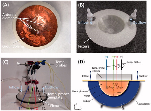
Figure 4. Setup for experimental assessment of phased array applicator in ex vivo tissue phantom.
Results
Effect of angular spacing between antennas
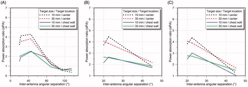
illustrates the αPA ratio for a 4-, 8- and 12-antenna array as a function of the inter-antenna angular spacing for the targets located at the centre and close to the chest wall of the small breast model. The small breast model (90 mm diameter) was selected as an example for illustrating the impact of antenna element spacing on αPA. The evaluated inter-antenna angular spacing are 20°, 22.5°, 45°, 75.5°, 90°, 112.5° and 135° for the 4-antenna array and 20°, 22.5° and 45° for the 8- and 12-antenna array (these are the largest angular spacing possible for this hemispherical applicator).
Figure 5. Average power absorption ratio of the 4-antenna array (A), 8-antenna array (B) and the 12-antenna array configuration (C) for the 10 mm edge length target and 30 mm edge length target located at the centre and near the chest wall of the small breast model for different inter-antenna angular spacing.
Effect of number of antennas in the array configuration
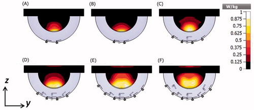
illustrates the αPA ratio as a function of number of antennas for the targets located at the centre and close to the chest wall of the small breast model for configurations with inter-antenna angular spacing of 22.5°. Array configurations of 2, 4, 8, 12, 16 and 20-antennas (with configurations shown in ) were evaluated. The specific absorption rate (SAR) cross-sections on the yz-plane in the small breast model and array configurations of 2, 4, 8, 12, 16 and 20 antennas with constant phase is shown in .
Figure 6. Average power absorbed ratio for the 10 mm edge length target and 30 mm edge length target located at the centre and near the chest wall of the small breast model for different number of antenna configuration (2, 4, 8, 12, 16 and 20) and inter-antenna angular spacing 22.5°.
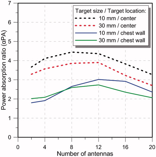
Figure 7. SAR cross-sections on the yz-planes of the small breast model and antenna array configurations of 2 (A), 4 (B), 8 (C), 12 (D), 16 (E) and 20 (F) antennas with constant phase. SAR normalised to the maximum value on the system.
Evaluation of a largest breast model
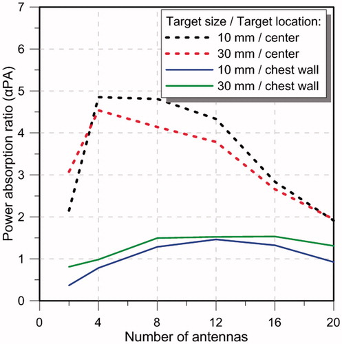
illustrates the αPA ratio as a function of number of antennas for the targets located at the centre and close to the chest wall of the large breast model for configurations with angular spacing of 22.5°. Array configurations of 2, 4, 8, 12, 16 and 20-antenna as shown in were evaluated.
Figure 8. Power absorbed ratio for the 10 mm edge length target and 30 mm edge length target located at the centre and near the chest wall of the large breast model for different number of antenna configuration (2, 4, 8, 12, 16 and 20) and inter-antenna angular spacing 22.5°.
SAR distribution of the 4-antenna array with optimised phases
The simulated SAR distribution in the yz-plane for the 4-antenna array configuration with constant phase with the objective of generating a focus in a centrally located target (indicated with a symbol × in the figure) at the midline of the breast is shown in and in the simulated experimental setup is shown in . The SAR distribution in the yz-plane with optimised phases (84.5°, 84.5°, 123°, 0°) with the objective of steering the energy deposition to a target (indicated with a symbol × in the figure) located in the right lobe of the breast with and offset of 22.5 mm from the breast midline is shown in and at the same location of the simulated experimental setup is shown in .
Figure 9. SAR cross-sections on the yz-plane with the 4-antenna array on the small breast model with all the antennas with constant phase (A) and phases optimised to create a focus in a laterally located target on the right lobe of the breast (B) and on the experimental setup with all the antennas with constant phase (C) and phases optimised to create a focus in a laterally located target on the right lobe (D). The symbol × indicates the location of the focus target.
Experimental results
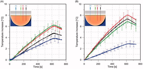
shows the simulated S11 with the simplified human breast model and the ex vivo chicken breast model and experimentally measured S11 with the ex vivo chicken breast phantom. shows experimentally measured (n = 3) transient temperature profiles during heating experiments performed in ex vivo tissue phantom, while applying a input power of 7.5 W per antenna with all the antennas fed with constant phase () and with optimised phase to steer the energy in a target 22.5 mm offset from the breast midline ().
Figure 10. Simulated S11 values of the 4-antenna array the with simplified human breast model and ex vivo chicken breast model (simulation of the experimental setup) (A) and S11 values of measurements with ex vivo chicken breast (B).
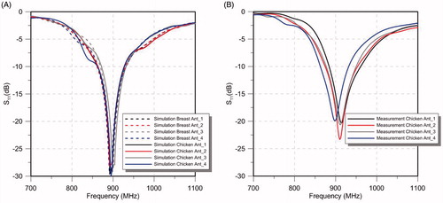
Figure 11. Experimentally measured (n = 3) transient temperature profiles with the 4-antenna phased array with constant phase (A), and phased optimised (B) to have the focus with an offset of 22.5 mm from the breast midline. Solid lines represent the mean value, error bars represent the range (maximum/minimum values). Temperature probes T1, T2, T3 and T4 positioned in the ex vivo tissue phantom. See Figure 4 for further details about the position of the temperature probes.
Discussion
This study was initiated to design and evaluate the feasibility of a phased array system for hyperthermia treatment of tumours at varying locations in the intact breast. The patch antenna presented in our previous research [Citation37] is proposed as the unitary element for this phased array system. 3D electromagnetic simulations were undertaken to assess the impact of inter-antenna spacing and number of antennas on energy deposition patterns within tumours at varying location within the breast.
Effect of antenna spacing on energy deposition patterns
When considering a small breast, for a 4-antenna array configuration, simulations indicated moderate increases in αPA values as inter-antenna spacing increased from 20° to 45° within both small and large targets (see ). However, further increases in inter-antenna angular spacing yielded sharp decreases in αPA values. For 8- and 12-antenna arrays, the highest αPA was found with inter-antenna spacing of 22.5° for the small target and at 20° for the large target (see ). Positioning the antenna with an inter-antenna angular spacing of less than 20° generated near-field interferences, which degraded the antenna impedance matching (i.e. S11 > -8.5 dB). In general, these results suggest that a good focussing effect can be achieved with inter-antenna spacing of ∼22.5° (or inter-antenna circumferential distance of ∼27.4 mm) for arrays incorporating 4–12 antennas.
Effect of number of antennas on energy deposition patterns
Considering an inter-antenna spacing of 22.5°, simulations were employed to assess the quality of focussing effect within small and large targets, positioned centrally or at depth (close to the chest wall) within the small breast of 90 mm diameter. As illustrated in , for central targets, similar performance was achieved with arrays employing 4–12 antennas, in which αPA ranged between 4.1 and 4.4 for small targets, and 3.5 and 3.9 for large targets. Although increasing the number of antennas beyond 12 yielded intense energy deposition within the target, αPA values rather decreased with the greater energy deposition outside the target, which could be seen in the SAR profiles illustrated in . The αPA curve shifted to the right for deep-seated targets positioned near the chest wall, with good performance achieved when using 8–16 antennas (). This rightward shift can be explained by the effects of greater attenuation of the E-field due to the increased distance between the target volume and the antennas. Collectively, these results suggest that arrays incorporating 8–12 antennas with an inter-antenna angular spacing of 22.5° provide sufficient flexibility to achieve good focussing within cubic target volumes of 1 cm3 and 27 cm3 positioned centrally or at depth (close to the chest wall) within the breast.
Simulations with the large breast model showed that for an inter-antenna spacing of 22.5°, a good focussing effect (αPA ∼4–5) was achieved with 4–8 antennas for central targets (). Similar to results with the small breast model, a larger number of antennas yielded the best focussing quality (αPA ∼1.5 with 8–16 antennas) for deep targets. Similar αPA values were achieved for central targets in the small breast and large breast. This finding may be attributed to reduced energy deposition in the target for the large breast being balanced by reduced energy deposition within the rest of the breast volume. However, for deep-seated targets, an optimum αPA value of ∼3 was achieved in the small breast compared to ∼1.5 in the large breast. This can be explained by the attenuation of heating effect due to the longer distances between the deep-seated target and antenna in the large breast, compared to the small breast.
Experimental evaluation
A 4-antenna array configuration with inter-antenna angular spacing of 45° was fabricated for experimental evaluation. Measured antenna reflection coefficients in an ex vivo chicken breast phantom were in good agreement with simulations of the simplified human breast model and the ex vivo chicken breast (). Positions of experimentally measured heating focal spots were in good agreement with SAR simulations. When employing antennas with constant phase, the measured temperature profiles illustrated the capability of delivering energy to central targets with the proposed applicator () using relatively low input power levels (7.5 W per antenna). By adjusting the relative phase of signals fed to individual antennas, as determined using the focussing algorithm presented in Wu et al. [Citation29], simulations and experiments indicated the feasibility of electrically steering focal spots ().
shows the ratio of the experimentally measured temperature rise for the case with focus at the centre compared to the lateral focus, following 60 s of heating at locations T1–T4. Also shown are the ratios of simulated SAR at the same locations. Both simulations and measurements indicate that central focussing (i.e. equal phase) compared to lateral focussing (i.e. adjusted phases) yields: reduced heating at location T1, moderate increases in heating at locations T2 and T3, and large increases at T4. Discrepancies between experiment and simulation may be due to: uncertainty in the location of temperature sensors during experiments, mismatch in tissue properties between experiment and simulation, and phase discrepancies along cables.
Table 2. Measured temperature and simulated SAR ratio center/lateral focusing at the locations T1, T2, T3 and T4.
These simulation and experimental results suggest good potential for heating targets in diverse locations within the breast. In particular, for central targets, the ratio of power deposition within the target volumes was approximately five times larger than in the full breast volume. While this study focussed on the analysis of parameters that affect the quality of electromagnetic focussing within target volumes, further investigations are necessary to assess the thermal profiles in simulation and experiment. Thermal analyses will be important for assessing the ability of the water bolus to effectively avoid heating the skin and non-targeted tissue between the target and the antennas. Another limitation of this study was that it did not consider dielectric heterogeneity between the target tissue and surrounding non-target regions. It is anticipated that dielectric contrast (especially effective conductivity) between the target and non-target tissue may yield increased power deposition within targets [Citation41,Citation45].
Several studies have reported phased antenna arrays positioned within a cylindrical geometry for delivering hyperthermia to breast targets [Citation28,Citation50]. Although the proposed system will require a water bolus for coupling electromagnetic energy to the breast while thermally sparing surface tissues, it will not require compression of the breast as in Dooley et al. [Citation51]. Due to the use of a hemispherical groundplane, the antennas can be positioned close to the breast target. Thus, the power levels required per antenna for achieving adequate heating are small compared to other applicators [Citation28,Citation29]. Hemispherical breast models and hemispherical groundplane applicators, with 25 mm-thick water bolus were considered for this work. Future evaluations of this applicator will incorporate patient-specific models with variable water bolus thickness, e.g. for patients in prone position with pendant breast. Differences in water bolus thickness, and in general, path length and heterogeneity of interfacing tissues between the antenna elements and the actual tumour will be compensated with individualised patient treatment planning, in which specific power and phase could be applied for each antenna element. This study considers the antenna located at a variable angular separation along the orthogonal axis and in the diagonals between the axes as an initial approximation. Future work will further investigate antenna distribution across the breast hemisphere with uniform solid angle. Future studies will assess the impact of heterogeneous tissue properties [Citation52], as well as extend our prior biothermal modelling efforts for assessment of the presented array design [Citation37].
Conclusions
Design, optimisation and experimental evaluation of a phased array for intact breast hyperthermia treatment was presented. Phased arrays incorporating a hemispheric groundplane and 2, 4, 8, 12, 16 and 20 antennas showed that an 8-antenna array achieved the highest αPA at centrally located targets, while a 12-antenna array achieved the highest αPA at deep seated targets for both small and large breast models. An experimental model comprising 4-antennas with optimised phases showed a favourable temperature increment of 7 °C on laterally located targets 22.5 mm off from the centre when compared with a temperature increase of only 3 °C on the opposite side. These results suggested that the applicator might be suitable for creating diverse energy deposition patterns at different locations within the intact breast.
Disclosure statement
The authors report no conflicts of interest.
Additional information
Funding
References
- Siegel R, Naishadham D, Jemal A. (2013). Cancer statistics, 2013. CA Cancer J Clin 63:11–30.
- Cancer.org. (2013). Cancer prevention and early detection. Facts and figures [Internet]. Atlanta, GA: American Cancer Society. Available from: http://www.cancer.org/research/cancerfactsfigures/cancerpreventionearlydetectionfactsfigures/ [last accessed 17 May 2016].
- Narod SA. (2012). Tumour size predicts long-term survival among women with lymph node-positive breast cancer. Curr Oncol 19:249–53.
- Morrow M, Strom EA, Bassett LW, et al. (2002). Standard for breast conservation therapy in the management of invasive breast carcinoma. CA Cancer J Clin 52:277–300.
- Bitton RR, Kaye E, Dirbas FM, et al. (2012). Toward MR-guided high intensity focused ultrasound for presurgical localization: Focused ultrasound lesions in cadaveric breast tissue. J Magn Reson Imaging 35:1089–97.
- Franckena M, Lutgens LC, Koper PC, et al. (2009). Radiotherapy and hyperthermia for treatment of primary locally advanced cervix cancer: results in 378 patients. Int J Radiat Oncol Biol Phys 73:242–50.
- van der Zee J, Gonzalez Gonzalez D, Rhoon GC, van, et al. (2000). Comparison of radiotherapy alone with radiotherapy plus hyperthermia in locally advanced pelvic tumours: a prospective, randomised, multicentre trial. Lancet 355:1119–25.
- Sneed PK, Stauffer PR, McDermott MW, et al. (1998). Survival benefit of hyperthermia in a prospective randomized trial of brachytherapy boost ± hyperthermia for glioblastoma multiforme. Int J Radiat Oncol Biol Phys 40:287–95.
- Jones EL, Oleson JR, Prosnitz LR, et al. (2005). Randomized trial of hyperthermia and radiation for superficial tumors. J Clin Oncol 23:3079–85.
- Datta NR, Ordóñez SG, Gaipl US, et al. (2015). Local hyperthermia combined with radiotherapy and-/or chemotherapy: recent advances and promises for the future. Cancer Treat Rev 41:742–53.
- Zagar TM, Oleson JR, Vujaskovic Z, et al. (2010). Hyperthermia combined with radiation therapy for superficial breast cancer and chest wall recurrence: a review of the randomised data. Int J Hyperthermia 26:612–7.
- Datta NR, Puric E, Klingbiel D, et al. (2016). Hyperthermia and radiation therapy in locoregional recurrent breast cancers: a systematic review and meta-analysis. Int J Radiat Oncol 94:1073–87.
- Landon CD, Park J-Y, Needham D, Dewhirst MW. (2011). Nanoscale drug delivery and hyperthermia: the materials design and preclinical and clinical testing of low temperature-sensitive liposomes used in combination with mild hyperthermia in the treatment of local cancer. Open Nanomedicine J 3:38–64.
- Evans SS, Repasky EA, Fisher DT. (2015). Fever and the thermal regulation of immunity: the immune system feels the heat. Nat Rev Immunol 15:335–49.
- Datta NR, Krishnan S, Speiser DE, et al. (2016). Magnetic nanoparticle-induced hyperthermia with appropriate payloads: Paul Ehrlich’s “magic (nano)bullet” for cancer theranostics? Cancer Treat Rev 50:217–27.
- Lee AHS. (2005). Why is carcinoma of the breast more frequent in the upper outer quadrant? A case series based on needle core biopsy diagnoses. Breast 14:151–2.
- Darbre PD. (2005). Recorded quadrant incidence of female breast cancer in Great Britain suggests a disproportionate increase in the upper outer quadrant of the breast. Anticancer Res 25:2543–50.
- Cancer.org. (2014). Detailed guide: Breast cancer [Internet]. Atlanta, GA: American Cancer Society. Available from: http://www.cancer.org/cancer/breastcancer/detailedguide/index [last accessed 17 May 2016].
- van der Zee J, De Bruijne M, Mens JWM, et al. (2010). Reirradiation combined with hyperthermia in breast cancer recurrences: overview of experience in Erasmus MC. Int J Hyperthermia 26:638–48.
- Moros EG, Peñagaricano J, Novàk P, et al. (2010). Present and future technology for simultaneous superficial thermoradiotherapy of breast cancer. Int J Hyperthermia 26:699–709.
- Shimm DS, Cetas TC, Oleson JR, et al. (1988). Regional hyperthermia for deep-seated malignancies using the BSD annular array. Int J Hyperthermia 4:159–70.
- Shi G, Joines WT. (2004). Design and analysis of annular antenna arrays with different reflectors. Int J Hyperthermia 20:625–36.
- Fenn AJ, King GA. (1994). Adaptive radiofrequency hyperthermia-phased array system for improved cancer therapy: phantom target measurements. Int J Hyperthermia 10:189–208.
- Fatehi D, van Rhoon GC. (2008). SAR characteristics of the Sigma-60-Ellipse applicator. Int J Hyperthermia 24:347–56.
- Verhaart RF, Verduijn GM, Fortunati V, et al. (2015). Accurate 3D temperature dosimetry during hyperthermia therapy by combining invasive measurements and patient-specific simulations. Int J Hyperthermia 31:686–92.
- Stauffer PR, Maccarini P, Arunachalam K, et al. (2010). Conformal microwave array (CMA) applicators for hyperthermia of diffuse chest wall recurrence. Int J Hyperthermia 26:686–98.
- Fenn AJ, Wolf GL, Fogle RM. (1999). An adaptive microwave phased array for targeted heating of deep tumours in intact breast: animal study results. Int J Hyperthermia 15:45–61.
- Stang J, Haynes M, Carson P, Moghaddam M. (2012). A preclinical system prototype for focused microwave thermal therapy of the breast. IEEE Trans Biomed Eng 59:2431–8.
- Wu L, McGough RJ, Arabe OA, Samulski TV. (2006). An RF phased array applicator designed for hyperthermia breast cancer treatments. Phys Med Biol 51:1–20.
- Asili M, Chen P, Hood AZ, et al. (2015). Flexible microwave antenna applicator for chemo-thermotherapy of the breast. IEEE Antennas Wirel Propag Lett 14:1778–81.
- Chakaravarthi G, Arunachalam K. (2015). Design and characterisation of miniaturised cavity-backed patch antenna for microwave hyperthermia. Int J Hyperthermia 31:737–48.
- Choi WC, Kim KJ, Kim J, Yoon YJ. (2014). Compact microwave radiator for improving heating uniformity in hyperthermia system. IEEE Antennas Wirel Propag Lett 13:1345–8.
- Converse M, Bond EJ, Veen BD, Hagness SC. (2006). A computational study of ultra-wideband versus narrowband microwave hyperthermia for breast cancer treatment. IEEE Trans Microw Theory Tech 54:2169–80.
- Iero DAM, Crocco L, Isernia T. (2014). Thermal and microwave constrained focusing for patient-specific breast cancer hyperthermia: a robustness assessment. IEEE Trans Antennas Propag 62:814–21.
- Zastrow E, Hagness SC, Van Veen BD. (2010). 3D computational study of non-invasive patient-specific microwave hyperthermia treatment of breast cancer. Phys Med Biol 55:3611–29.
- Nguyen PT, Abbosh A, Crozier S. (2015). Microwave hyperthermia for breast cancer treatment using electromagnetic and thermal focusing tested on realistic breast models and antenna arrays. IEEE Trans Antennas Propag 63:4426–34.
- Curto S, Prakash P. (2015). Design of a compact antenna with flared groundplane for a wearable breast hyperthermia system. Int J Hyperthermia 31:726–36.
- Haynes M, Stang J, Moghaddam M. (2012). Microwave breast imaging system prototype with integrated numerical characterization. Int J Biomed Imaging 1:1–18.
- Gabriel S, Lau RW, Gabriel C. (1996). The dielectric properties of biological tissues: III. Parametric models for the dielectric spectrum of tissues. Phys Med Biol 41:2271–93.
- Kaatze U. (2007). Reference liquids for the calibration of dielectric sensors and measurement instruments. Meas Sci Technol 18:967–76.
- Zastrow E, Davis SK, Lazebnik M, et al. (2008). Development of anatomically realistic numerical breast phantoms with accurate dielectric properties for modeling microwave interactions with the human breast. IEEE Trans Biomed Eng 55:2792–800.
- Christ A, Klingenbock A, Samaras T, et al. (2006). The dependence of electromagnetic far-field absorption on body tissue composition in the frequency range from 300 MHz to 6 GHz. IEEE Trans Microw Theory Tech 54:2188–95.
- Garcia-Miquel A, Curto S, Vidal N, et al. Compact microwave applicator for thermal therapy of breast cancer: comparative assessment of arrays operating at 434 and 915 MHz. European Conference on Antennas and Propagation (EUCAP), Davos, Switzerland; 2016. p. 1–4.
- Bahramiabarghouei H, Porter E, Santorelli A, et al. (2015). Flexible 16 antenna array for microwave breast cancer detection. IEEE Trans Biomed Eng 62:2516–25.
- Curto S, Ruvio G, Ammann MJ, Prakash P. A wearable applicator for microwave hyperthermia of breast cancer: Performance evaluation with patient-specific anatomic models. 2015 International Conference on Electromagnetics in Advanced Applications (ICEAA), Torino, Italy; 2015. p. 1159–62.
- Paulides MM, Bakker JF, Zwamborn APM, van Rhoon GC. (2007). A head and neck hyperthermia applicator: theoretical antenna array design. Int J Hyperthermia 23:59–67.
- Lagarias JC, Reeds JA, Wright MH, Wright PE. (1998). Convergence properties of the Nelder–Mead simplex method in low dimensions. SIAM J Optim 9:112–47.
- Computer Simulation Technology GmGH Microwave Studio [Internet]. Available from: http://www.cst.com [cited 17 May 2016].
- Arunachalam K, Maccarini PF, Stauffer PR. (2008). A thermal monitoring sheet with low influence from adjacent waterbolus for tissue surface thermometry during clinical hyperthermia. IEEE Trans Biomed Eng 55:2397–406.
- Ju K-C, Tseng L-T, Chen Y-Y, Lin W-L. (2006). Investigation of a scanned cylindrical ultrasound system for breast hyperthermia. Phys Med Biol 51:539–55.
- Dooley WC, Vargas HI, Fenn AJ, et al. (2008). Randomized study of preoperative focused microwave phased array thermotherapy for early-stage invasive breast cancer. Cancer Ther 6:395–408.
- van Leeuwen CM, Crezee J, Oei AL, et al. (2016). 3D radiobiological evaluation of combined radiotherapy and hyperthermia treatments. Int J Hyperthermia 33:160–69.