
Abstract
Microwave ablation (MWA) has been proposed to suffer less from the heat sink effect compared to radiofrequency ablation but has been reported to cause extension of the ablation zone along intrahepatic vessels in clinical practice. To study this effect in detail, eight fresh porcine livers were perfused in an ex vivo organ perfusion system. Livers were perfused with oxygenated, O-positive human blood at 37 °C. Perfusion was discontinued immediately before ablation in the non-perfused group (n = 4) whilst in the perfused group (n = 4) perfusion was maintained during MWA (140 W X 2 min). Large intrahepatic vessels (> 6 mm) were avoided using ultrasound. MWA zones were bisected within 30 min of perfusion termination and sections were fixed in formalin and stained with H&E and NADH to assess cell viability. Magnetic resonance imaging (MRI) was performed on two livers (one perfused, one non-perfused) to provide imaging correlation before sectioning. Twenty-one out of a total of 30 MW ablation zones (70%) showed extension of the ablation zone along a vessel. There was no statistically significant difference (p = 1) in the incidence of ablation zone extension between perfused (9/13, 69%) and non-perfused organs (12/17, 71%). MRI also demonstrated ablation zone extension along blood vessels correlating with macroscopy in two livers. NADH staining also confirmed extension of the ablation zone. Liver MWA appears to be commonly associated with propagated thermal injury along adjacent vessels and occurs independent of active blood flow. In order to avoid possible complications through non-target tissue injury, this effect requires further investigation.
Introduction
Percutaneous microwave ablation (MWA) is increasingly being used in the treatment of both primary and secondary liver tumours [Citation1–3]. In MWA, kinetic energy is transferred when polar molecules, predominantly water, are forced to continuously realign within an oscillating electromagnetic field, in a phenomenon known as dielectric hysteresis [Citation4]. In clinical practice, predictable ablation zone dimensions are important for successful treatment and to avoid complications resulting from damage to nearby structures [Citation5]. Factors affecting ablation zone volumes include the amount of energy transferred, tissue response to temperature changes and tissue perfusion on macro and microvascular levels [Citation4,Citation6]. MWA is thought to suffer less from the cooling effect of perfusion known as the heat sink effect compared to radiofrequency ablation due to the speed of energy deposition [Citation7,Citation8]. Manufacturers suggest that because of these factors, MWA produces more predictable ablation zones and improved destruction of perivascular tumours.
Whilst this advantage may improve treatment of perivascular tumours, heat deposition to vessels may have adverse consequences such as extension of the ablation zone along vascular planes and thrombosis of intrahepatic vessels. Thrombosis of intrahepatic vessels has been reported in the literature and is a recognised complication [Citation9]. However extension of the ablation zone along vessels has only been reported once in a patient where there was evidence of ablation zone extension around a thrombosed hepatic vein branch [Citation10]. Perivascular extension of the ablation zone has been reported as an incidental finding in two in vivo animal studies of liver MWA [Citation11,Citation12]. A more recent in vivo study demonstrated vessel damage away from the ablation zone but did not mention extension of the ablation zone in the perivascular parenchyma [Citation13]. This effect is important because thermal injury to vessels may precipitate thrombosis, as seen in the only reported clinical case and in vivo studies [Citation10–13]. Vascular thrombosis is not rare following MWA [Citation9], and in some cases can be a serious complication [Citation14,Citation15]. The clinical sequelae of hepatic vessel thrombosis include lobar infarcts and liver decompensation which can be devastating in patients with low liver reserve such as those with cirrhosis and fatty liver disease [Citation13,Citation14]. The pathogenesis of both thrombosis and extension of the ablation zone along hepatic vessels after MWA has not been investigated fully [Citation14].
The aim of this study was to investigate the extension of MWA along intrahepatic vessels using a perfused liver model. Two hypotheses have been proposed in the literature to explain this effect. The first is that superheated blood flows away from the ablation zone causing thermal damage to vessels and the second states that thrombosis is the primary event and provides the substrate for heat to be conducted away from the ablation zone extending the ablation zone [Citation11–13]. To determine whether extension of the ablation zone is caused by blood flow, we compared the incidence of this effect in two groups. In the perfused group, porcine livers underwent MWA whilst being perfused whereas in the non-perfused group perfusion was halted during MWA. The incidence of ablation zone extension was compared macroscopically and microscopically in both groups.
Methods and material
Porcine livers
This study did not require ethical approval from an institutional review board as the pig livers were sourced from a slaughterhouse. Livers were obtained from eight healthy domestic pigs using transplant retrieval techniques within 10 min of termination at the slaughterhouse. Livers were dissected from the complete set of abdominal viscera having been removed from the terminated animals. The bile duct, portal vein and the hepatic artery were isolated. In order to clear blood from the hepatic vasculature and to cool the liver parenchyma rapidly, the portal vein and hepatic artery were cannulated and perfused with 2 L of cold (4 °C), heparinised UW (University of Wisconsin–Belzer UW® Bridge to Life, Columbia, South Carolina) solution (5000 IU of heparin per litre of University of Wisconsin Solution-UW). The portal vein, hepatic artery and supra/infra hepatic inferior vena cava (IVC), were divided at their attachments to the liver. The harvested livers were transported to the perfusion laboratory in cold storage at 4 °C human organ transplantation.
Liver perfusion
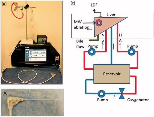
After 4 h of cold storage to allow standardisation of the preservation period, the livers were placed into an organ perfusion chamber and the hepatic artery, portal vein and common bile duct cannulated with 3 and 8 mm cannulas and a 2-mm venepuncture tube (Surflo® Winged Infusion Set, Terumo, Tokyo, Japan), respectively. The cystic duct was ligated to prevent gallbladder bile from flowing into the common bile duct. Bile production was monitored continuously as a measure of organ function/viability during the experiment. Each liver was then perfused with time-expired, pH corrected (with Sodium Bicarbonate - NaHCO3 8.4% w/v), O-positive whole blood obtained from the UK Blood Transfusion service. Perfusion was maintained by an organ perfusion circuit () and blood pH was titrated to a range of 7.35–7.45 by continuously checking pH with an inline probe and correcting with 5 ml aliquots of NaHCO3 added to the perfusion circuit. A mixed gas containing 14% O2, 5% CO2 and 81% N2 was used to oxygenate blood, which was also warmed to 37 °C using a heat exchanger in the oxygenator (Capiox Therumo® SX 10, Therumo Cardiovascular Systems, Terumo Shibuya, Tokyo, Japan). Blood was perfused via the hepatic artery and portal vein at a rate of 150 ml/min each for 30 min using a purpose-built dual roller pump (Watson Marlow, Cornwall, UK) perfusion system. The rate of 150 ml/min each via the portal vein and hepatic artery was selected based on the results of a set of preliminary experiments previously designed to select the perfusion rate which provided the optimum peripheral tissue perfusion with minimum or no pressure induced parenchymal damage [Citation16]. Perfusion was continued during MWA in the perfused arm (n = 4) and discontinued in the non-perfused arm (n = 4).
Figure 1. Microwave Ablation system and ex vivo perfusion system. (a) MWA system – Acculis MTA system® (AngioDynamics, Denmead, Hampshire). (b) MW applicator – Acc2i pMTA 14cm standard applicators (AngioDynamics, Denmead, Hampshire). (c) Ex vivo perfusion system –diagram showing the ex vivo perfused pig liver model. The perfusate was O-ve human blood (time expired) oxygenated using a mixed gas containing 14% O2, 5% CO2 and 81% N2 and warmed to 370 °C using the heat exchanger of the oxygenator. HA: Hepatic artery; PV: Portal vein; LDF: Laser Doppler Flowmetry; MW: Microwave.
Assessment of perfusion
The adequacy and standardisation of perfusion between livers was assessed by measuring surface microcirculation at a site distant to the ablation zones. A dual channel Laser Doppler Flowmetry (LDF) system (DRT4; Moor Instruments, Ltd, Axminister, UK) with a laser source and a multi-detector integrating laser Doppler probe (DP7; Moor Instruments, Ltd, Axminster, UK) was used to measure microcirculation of the ex vivo perfused livers and the method has been described previously [Citation17]. The LDF provides arbitrary measurements that reflect relative changes in the microcirculation of the organ being assessed.
Microwave ablation
MWA was performed on healthy porcine livers using an Acculis MTA system with a 2.45 GHz operating frequency, with Acc2i pMTA 14 cm standard applicators (AngioDynamics, Denmead, Hampshire) (). The power selected was 140 W which was delivered for 2 min based on the unit’s clinical practice and findings of the previously published preliminary experiments [Citation16]. The MWA probe was inserted into the liver under ultrasound guidance (Hitachi EUB 6500® Hitachi, Tokyo, Japan) in order to avoid puncture of large intrahepatic vessels (>6 mm in diameter) akin to clinical practice. At least one ablation zone was produced in each of the four lobes of the porcine liver. The formation of the ablation zone was observed with ultrasound which demonstrated a characteristic echogenic focus in keeping with gas which dissipated over minutes and left a hypoechoic region of ablation. A labelled marker (22 gauge spinal needle, Vygon, Écouen, France) was inserted along the MWA applicator in a sagittal plane following the ablation for purposes of identification and to guide transection.
Evaluation of ablation zones
Once all the ablation zones were produced, each liver was disconnected from the ex vivo perfusion system. Each MWA zone was bisected along the plane of the marker in order to assess its morphology. Vascular extension was defined as an area of ablation (seen on macroscopic examination of the white area of tissue injury—) extending along a hepatic vessel for at least 5 mm outside of the main ablation zone. These regions were then snap frozen and cryosections prepared. Macroscopic evidence of extension of the ablation zone along vessels either traversing or adjacent to the MWA zone was assessed independently by two authors (SS and PNS).
Figure 2. Sampling method for Haematoxylin and Eosin (H&E) and nicotinamide adenine dinucleotide (NADH) staining. Schematic representation of the method of bisecting the ablation zone and obtaining sections for snap freezing. The ablation zone is bisected along the plane of the probe and one half is fixed in formalin for processing for histology. A 5-mm slice is obtained from the other half which is mounted with the plane of the probe facing up and snap frozen in liquid nitrogen prior to obtaining cryosections.
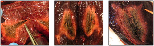
In order to assess histological evidence of tissue ablation along the length the vessels, one half of the bisected specimen was fixed in formalin and paraffin embedded with the mid sagittal plane facing up. Five consecutive 4 µm sections from the side of the mid sagittal plane were obtained and mounted on charged glass slides. These were stained with Hematoxylin and Eosin (H&E). In order to obtain cryosections, which corresponded with the paraffin sections, a 5 mm slice was obtained from the remaining half of the bisected ablation zone. These were mounted fresh with the mid sagittal plain facing up, snap frozen in liquid nitrogen and stored at –80 °C. The method of bisecting the ablation zone and obtaining a section snap freezing is shown in diagrammatic form in . Cell viability in areas of coagulation necrosis following thermal ablation was evaluated using histochemical staining for nicotinamide adenine dinucleotide (NADH) as previously described [Citation18]. NADH is a ubiquitous coenzyme present in both cytoplasm and mitochondria of viable cells. A validated protocol was used for NADH staining [Citation19]. A blue formazan deposit in the nuclei as well as the cytoplasm indicates cellular enzyme activity; hence cell viability at the time of tissue preservation.
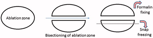
Figure 3. Macroscopy of microwave ablation zone. Macroscopic appearances of the extension zone along vessels in three different ablation zones. These ablation zones demonstrate the zonal anatomy of a central dark zone (carbonised tissue), surrounding white zone (non-carbonised thermal coagulation) and an outer red zone (boundary of the ablation zone).
Magnetic resonance imaging (MRI)
MRI was performed on two livers (one perfused, one non-perfused) each containing 4 MW ablation zones for imaging-histological correlation. Imaging was performed with a 1.5-Tesla system (Intera; Philips Medical System, Eindhoven, Netherlands). MRI comprised T1W, T2W turbo spin echo and 3 D WATSf sequences. The 3 D WATSf sequence is a fast low angle shot gradient echo sequence with water selective excitation (TR: 20 ms, TE: 7.9 ms, flip angle 50°, slice thickness 1.5 mm, every 0.75 mm). After imaging, livers were serially sectioned in the sagittal plane to register MRI and histological slices, and make assertions regarding the imaging appearances of pathological processes. The MR images were interpreted by a radiologist with expertise in hepatobiliary imaging and hepatic ablation.
Data analysis
Stata/IC 13.1 for Windows, StataCorp (Texas USA) was used for data analysis. One-way ANOVA was used for the comparison of the pre-ablation and post ablation microcirculation in the four perfused livers. The change in microcirculation during perfusion was analysed by an unpaired t-test. A Chi-square test was performed to compare the frequencies of vascular extension in perfused versus none perfused livers.
Results
Organ parameters and perfusion
The pre-perfusion weight of the perfused 2170 g (SD ±123) and non-perfused livers 2114 g (SD ±448) were not significantly different (p = 0.82). The mean temperature of the perfused and non-perfused livers following the 30 minutes of warming was comparable at 35.3 °C (SD ±0.35) and 35.6 °C (SD ±0.40) (p = 0.30), respectively. Assessment of tissue perfusion was performed by assessing microcirculation parameters. The microcirculation of the perfused groups of livers increased progressively from a mean pre-ablation flux of 14.09 ± 1.8 to a post-ablation flux of 17.23 ± 3.3 arbitrary perfusion units (p = 0.006). All livers had an increase in microcirculation as a result of re-perfusion and re-warming (p = 0.34). Bile flow continued throughout the period of liver perfusion, confirming organ viability.
Macroscopic assessment of MWA
Microwave ablation was performed under ultrasound guidance and showed characteristic gas and vapour formation, which travelled away from the ablation zone. The ablation zone demonstrated zonal anatomy. There was a central dark zone surrounding the applicator tract, suggestive of carbonisation. The dark zone was encircled by a white and an outer red zone (). The white zone corresponded to non-carbonised coagulated tissue and the red zone to the boundary of the ablation zone. The median number of ablations performed per liver was 4 (range 1–5). The ablation zone extended along the course of a vessel () in 21 (9 perfused, 12 non-perfused) out of 30 lesions (70%). There was no significant difference in the number of ablation zones, which contained an extension of the MWA along at least one vessel in perfused (9/13, 69%) and non-perfused groups (12/17, 71%) (p = 1.0). The size of the vessels along which ablation zone extension was seen ranged between 2 and 8 mm in diameter (measured by a Vernier calliper), with no evidence of thrombosis in any of these vessels. Both investigators (SS and PNS) were able to identify all the vessels with an extension MWA zone in all of the ablation zones. Hence, inter observer variation was not assessed.
Magnetic resonance imaging
On all MRI sequences, the ablation area consisted of three qualitatively distinct zones. There was a central, inner and outer zone, corresponding to the dark, white and red zones observed macroscopically (). These zones had the following signal characteristics: the central zone was hypointense on T1 corresponding to carbonised tissue, the inner white zone was hypointense on T1W and T2W images in keeping with thermal coagulation and the outer zone was hyperintense on (T1W) and isointense on T2W images in keeping with the boundary of the ablation zone (). The contrast between zones was most conspicuous on 3 D WATSf imaging which showed a hyper intense rim and predominantly isointense inner zone. There was no significant difference in the signal characteristics of ablation zones between the perfused and non-perfused groups.
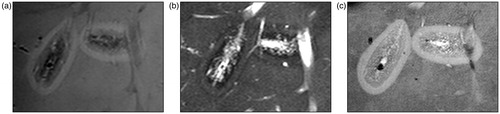
Figure 4. Comparison of Microwave ablation (MWA) zone characteristic with the Magnetic resonance (MR) image appearance. (a) A macroscopic section showing the extension of the ablation zone along a hepatic vein on the leftmost ablation zone (arrow) at an approximately similar plane as the following MR image. Zonal anatomy of the ablation again demonstrated with a central dark (carbonised) zone, inner white zone (coagulated) and outer zone (boundary). (b) Axial 3D Fast low angle shot gradient echo sequence with water selective excitation (3D WATSf) image showing two ablation zones at a similar plane to macroscopic slice. The peripheral, higher signal component of the leftmost ablation zone extends along the adjacent hepatic veins (arrow).
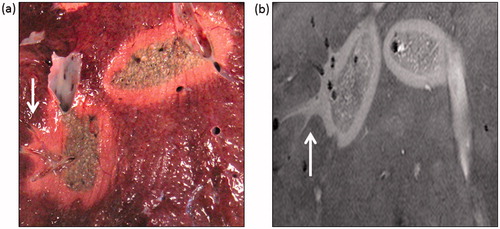
The vascular extension was most apparent in the water selective sequences (). The size of the vessels on MRI with extension of the MWA was also in the range of 2–8 mm in diameter for both groups. The distance the ablation zone extended along vessels ranged from approximately 0.5 to 1 cm (measured from the outer zone on MR images).
Figure 5. Magnetic resonance appreance of T1 and T2 weighted images and 3dWatSF imges. (a) T1-weighted imaging, turbo spin echo (T1W TSE) shows two ablation zones. Each ablation zone demonstrates zonal anatomy; an outer hyperintense rim, inner hypointense T1 signal, and further hypointense central region. compared to background liver. (b) T2-weighted imaging, turbo spin echo (T2W TSE) also shows an outer zone which is slightly hyperintense and a hypointense inner and central zone. (c) 3d WATSf imaging shows a hyper intense rim and predominantly isointense inner and central zone.
Microscopic appearance of the perivascular zone
The central dark zone corresponded to carbonised coagulated tissue and the white zone to non-carbonised coagulated tissue. The outer red zone was the boundary of the ablation zone which contained some viable cells as demonstrated on NADH staining.
H&E stained paraffin sections and cryosections showed a zone of thermally damaged hepatocytes, characterised by shrunken and eosinophilic cytoplasm and hyperchromatic, homogeneous nuclei in the periphery of the vessels adjacent to the MWA zone. Thermal damage was also seen to extend along the hepatic veins and portal tracts including branches of the hepatic artery and portal vein on H&E stained sections.
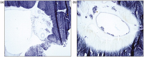
In NADH stained sections, perivascular extension of the ablation zone was evident by the absence of blue formazan nuclear and cytoplasmic deposits, compared with areas around vessels with no extension (). The NADH stained sections also demonstrated perivascular MWA extension along both portal tracts and hepatic veins.
Figure 6. Nicotinamide adenine dinucleotide (NADH) staining. Extension of the ablation zone in the perivascular region demonstrated by zone of absent blue formazan deposit in the nuclei as well as the cytoplasm in the perivascular zone in a vessel with extension of MWA.
Discussion
This is the first study to investigate the influence of perfusion on the extension of the ablation zone along vessels following liver MWA. An organ perfusion system was utilised to study the effect of blood flow and parenchymal perfusion on the incidence of vascular extension following MWA. Microwave ablation zones were morphologically consistent with previous studies [Citation14,Citation16,Citation20–23]. There was a central dark zone, surrounded by a white zone and an outer red zone which demonstrated expected characteristics on NADH staining [Citation16]. The dark and white zones were devoid of staining in keeping with non-viable cells representing thermal coagulation and the red zone had patchy NADH staining in keeping with some viability in the boundary of the ablation zone. The outer hyperintense rim on MRI (T1W) corresponded with haemorrhage and oedema (red zone), the inner hypointense zone (T1W and T2W) with coagulation necrosis (white zone) on H&E staining and the central hypointense zone (T1W) with carbonised tissue surrounding the applicator tract [Citation23].
We demonstrate for the first time that vascular extension of the ablation zone following liver MWA occurs independent of blood flow. The ablation zone was seen to extend in the perivascular space and was devoid of NADH staining, confirming cell death.
Histological examination confirmed that the majority of MW ablation zones had extension along vessels and involved the endothelium, adventitia and perivascular liver parenchyma. The mechanism of extension of the MWA along the vessels is uncertain. Two in vivo porcine studies of liver MWA mentioned perivascular extension as incidental findings whereby the ablation zone extended along and around vessels away from the ablation zone [Citation11,Citation12]. Only one in vivo study was dedicated to studying damage to vessels outside the ablation zone [Citation13]. These studies propose three different hypotheses explaining why this phenomenon occurs. Wright et al. [Citation11] suggest that this effect could be due to water vapour tracking along vessels and thus causing extension of the ablation zone. The second hypothesis by Yu et al. states that the intravascular thrombosis is the primary event which then conducts heat away from the target [Citation12]. The study by Meloni et al. [Citation13] hypothesised that hot blood flowing through vessels away from the ablation zone damages the vessel wall.
If extension of the ablation zone were due to superheated blood or vapour causing injury to the endothelium, it would require blood flow to transport it along vessels in order to cause damage. We have shown using the perfused and non-perfused groups that the pathogenesis of the phenomenon is not dependent on blood flow as there was a comparable incidence of vascular extension in both perfused and non-perfused arms. The vessels affected in the perfused group of livers included both hepatic and portal vein branches on post ablation histology. Theoretically these vessels carry blood in opposite directions but this was not observed directly in our experiments. These observations are indicative but not categorical in dismissing the hypothesis of Wright et al as it is possible that water vapour may emanate in random directions from the site of ablation.
Yu et al. [Citation12] suggested that thrombosis of the vessel was a primary event and facilitates heat conduction, leading to extension of the ablation zone. In this study, we did not observe thrombosis in any of our histological samples, however given the short interval between ablation and examination this may be expected. Another difference to previous studies was that the ablation zone extended along portal tracts which included arteries in contrast to previous in vivo studies [Citation11–13].
The findings of the study therefore suggest another possibility, where the ablation zone extends in the perivascular parenchyma and causes thermal damage from “outside in”; rather than “inside out” as suggested by previous in vivo studies [Citation11–13]. The properties of the perivascular parenchyma may allow the ablation zone to extend along tissue planes and cause thermal damage to vessels independent of blood flow. Further work is required to determine what these properties are.
The phenomenon of perivascular extension may have clinical significance. MWA operates at a higher temperature and has the advantage of creating faster and larger ablation zones from a single applicator when compared to RFA [Citation8]. It is often preferred for perivascular lesions due to a reduced heat sink effect [Citation24]. Due to the difficulty in monitoring the ablation zone during MWA procedures [Citation25,Citation26], it is important that a predictable volume of ablation is produced especially when the target lesion is near important structures such as major bile ducts and hepatic vessels [Citation27]. Our study shows that ablation zones may extend along small to medium sized vessels, which are impossible to avoid in clinical practice. Although vascular thrombosis is a known complication of ablation [Citation4], perivascular extension may contribute to instances where thrombosis is found outside of the ablation zone. Furthermore, this study was carried out with intentional sitting of ablation zones away from major vessels to simulate clinical practice. Therefore the risk of major liver vessel thrombus formation cannot be determined from this study.
The findings of this study may also aid evaluation of follow-up imaging in patients receiving liver MWA for cancer. MRI was clearly able to subdivide the ablation zones into areas of differing macroscopic and histological appearances [Citation28]. The inner zone which corresponded to total cell kill should be used to determine successful ablation of a lesion. In addition, both zonal anatomy and ablation zone extension were more conspicuous on water selective sequences (). Therefore, we recommend that water selective sequences are included when following up this complication.
This study has three main limitations. Although efforts were made to simulate physiological conditions in this porcine model, the frequency of perilesional vascular extension following liver MWA may differ between the experimental model, an in vivo porcine model and in patients due to a lower flow rate used in this setting and different tissue properties. Although the frequency of this effect cannot be predicted from this study, findings suggest that the pathogenesis of extension of the ablation zone is independent of blood flow. Secondly, we removed the ablation sites and dissected the involved liver parenchyma within thirty minutes of ablation which may not have allowed sufficient time for the effects of perivascular thermal damage to proceed to vessel thrombosis. Finally, heparinised blood was used for perfusion which may have reduced the risk of thrombosis.
Conclusion
The major finding of this study is that extension of the ablation zone occurs independent of blood flow in contrast to previous hypotheses in the literature. The mechanism for heat conduction however, has not been established and further research is required to determine clinical impact and whether this effect can be avoided.
Acknowledgments
We would like to thank Professor Janice Holton and Ms. Khadhija Miller of the UCL Department of Neurology for the advice and technical support for the cryosectioning and NADH staining. We would also like to thank Dr Randi Drees and Dr Richard Lam from the Royal Veterinary College Radiology Department (London) for their help in obtaining MR imaging of the two porcine livers.
Disclosure statement
The authors report no conflicts of interest.
Additional information
Funding
References
- Boutros C, Somasundar P, Garrean S, et al. (2010). Microwave coagulation therapy for hepatic tumors: review of the literature and critical analysis. Surgical Oncol 19:e22–32.
- Yu Z, Liu W, Fan L, et al. (2009). The efficacy and safety of percutaneous microwave coagulation by a new microwave delivery system in large hepatocellular carcinomas: four case studies. Int J Hyperthermia 25:392–8.
- Li D, Kang J, Madoff DC. (2014). Locally ablative therapies for primary and metastatic liver cancer. Expert Rev Anticancer Therapy 14:931–45.
- Lubner MG, Brace CL, Hinshaw JL, et al. (2010). Microwave tumor ablation: mechanism of action, clinical results, and devices. J Vasc Interv Radiol 21(8 Suppl):S192–S203.
- Ding J, Jing X, Liu J, et al. (2013). Complications of thermal ablation of hepatic tumours: comparison of radiofrequency and microwave ablative techniques. Clin Radiol 68:608–15.
- Lopresto V, Pinto R, Farina L, et al. (2017). Treatment planning in microwave thermal ablation: clinical gaps and recent research advances. Int J Hyperthermia 33:83–100.
- Takamura M, Murakami T, Shibata T, et al. (2001). Microwave coagulation therapy with interruption of hepatic blood in- or outflow: an experimental study. J Vasc Interventional Radiol 12:619–22.
- Wright AS, Sampson LA, Warner TF, et al. (2005). Radiofrequency versus microwave ablation in a hepatic porcine model. Radiology 236:132–9.
- Meloni MF, Andreano A, Lava M, et al. (2010). Segmental portal vein thrombosis after microwave ablation of liver tumors: report of two cases. Eur J Radiol Extra 76:e95–8.
- Singh S, Siriwardana PN, Johnston EW, et al. (2016). Perivascular parenchymal extension of the ablation zone following liver microwave ablation. BMJ Case Reports 2016. doi: 10.1136/bcr-2015-212871
- Wright AS, Lee FT, Mahvi DM. (2003). Hepatic microwave ablation with multiple antennae results in synergistically larger zones of coagulation necrosis. Ann Surg Oncol 10:275–83.
- Yu NC, Raman SS, Kim YJ, et al. (2008). Microwave liver ablation: influence of hepatic vein size on heat-sink effect in a porcine model. J Vasc Interv Radiol 19:1087–92.
- Meloni MF, Andreano A, Bovo G, et al. (2011). Acute portal venous injury after microwave ablation in an in vivo porcine model: a rare possible complication. J Vasc Interv Radiol 22:947–51.
- Chiang J, Willey BJ, Del Rio AM, et al. (2014). Predictors of thrombosis in hepatic vasculature during microwave tumor ablation of an in vivo porcine model. J Vasc Interv Radiol 25:1965–71.e2.
- Kojima Y, Suzuki S, Sakaguchi T, et al. (2000). Portal vein thrombosis caused by microwave coagulation therapy for hepatocellular carcinoma: report of a case. Surgery Today 30:844–8.
- Siriwardana PN, Singh S, Johnston EW, et al. (2017). Effect of hepatic perfusion on microwave ablation zones in an ex vivo porcine liver model. J Vasc Interv Radiol 28:732–9.
- Swiontkowski MF. (1991). Laser Doppler flowmetry—development and clinical application. Iowa Orthopaedic J 11:119–26.
- Neumann RA, Knobler RM, Pieczkowski F, et al. (1991). Enzyme histochemical analysis of cell viability after argon laser-induced coagulation necrosis of the skin. J Am Acad Dermatol 25:991–8.
- Hess R, Scarpelli DG, Pearse AG. (1958). The cytochemical localization of oxidative enzymes. II. Pyridine nucleotide-linked dehydrogenases. J Biophys Biochem Cytol 4:753–60.
- Ryan TP, Brace CL. (2017). Interstitial microwave treatment for cancer: historical basis and current techniques in antenna design and performance. Int J Hyperthermia 33:3–14.
- Lopresto V, Pinto R, Cavagnaro M. (2014). Experimental characterisation of the thermal lesion induced by microwave ablation. Int J Hyperthermia 30:110–8.
- Awad MM, Devgan L, Kamel IR, et al. (2007). Microwave ablation in a hepatic porcine model: correlation of CT and histopathologic findings. HPB 9:357–62.
- Hyodoh H, Hyodoh K, Takahashi K, et al. (1998). Microwave coagulation therapy on hepatomas: CT and MR appearance after therapy. J Magn Reson Imag 8:451–8.
- Strickland AD, Clegg PJ, Cronin NJ, et al. (2002). Experimental study of large-volume microwave ablation in the liver. Br J Surg 89:1003–7.
- Correa-Gallego C, Karkar AM, Monette S, et al. (2014). Intraoperative ultrasound and tissue elastography measurements do not predict the size of hepatic microwave ablations. Acad Radiol 21:72–8.
- Zhang M, Castaneda B, Christensen J, et al. (2008). Real-time sonoelastography of hepatic thermal lesions in a swine model. Med Phys 35:4132–41.
- Wang X, Sofocleous CT, Erinjeri JP, et al. (2013). Margin size is an independent predictor of local tumor progression after ablation of colon cancer liver metastases. Cardiovasc Intervent Radiol 36:166–75.
- Ringe KI, Wacker F, Raatschen H-J. (2015). Is there a need for MRI within 24 hours after CT-guided percutaneous thermoablation of the liver?. Acta Radiologica 56:10–7.