
Abstract
Purpose: To evaluate the feasibility and efficacy of deep regional hyperthermia with the use of mobile insulator sheets in a capacitively coupled heating device.
Materials and methods: The heat was applied using an 8-MHz radiofrequency-capacitive device. The insulator sheet was inserted between the regular bolus and cooled overlay bolus in each of upper and lower side of the electrode. Several settings using the insulator sheets were investigated in an experimental study using an agar phantom to evaluate the temperature distributions. The specific absorption rate (SAR) distributions in several organs were also computed for the three-dimensional patient model. In a clinical prospective study, a total of five heating sessions were scheduled for the pelvic tumours, to assess the thermal parameters. The conventional setting was used during the first, third and fifth treatment sessions, and insulator sheets were used during the second and fourth treatment sessions.
Results: In the phantom study, the higher heating area improved towards the centre when the mobile insulator sheets were used. The subcutaneous fat/target ratios for the averaged SARs in the setting with the mobile insulator (median, 2.5) were significantly improved compared with those in the conventional setting (median, 3.4). In the clinical study, the thermal dose parameters of CEM43°CT90 in the sessions with the mobile insulator sheets (median, 1.9 min) were significantly better than those in the sessions using a conventional setting (median, 1.0 min).
Conclusions: Our novel heating method using mobile insulator sheets was thus found to improve the thermal dose parameters. Further investigations are expected.
Introduction
Hyperthermia (HT) is usually defined as a temperature elevation in the range of 39–45 degrees, and temperatures beyond this range are considered as thermal ablation [Citation1]. HT is known to have a directly cytotoxic effect on cancer cells, while also acting as a radio-sensitiser and a chemo-sensitizer [Citation1]. The efficacy of radiotherapy (RT) plus HT in various cancers was demonstrated and confirmed by randomised phase-III clinical trials [Citation2–6]. In the experimental setting, substantial radiosensitisation was observed at temperatures of >41 °C, and there was a clear thermal–dose effect relationship in sensitisation [Citation7–14]. Numerous reports on superficial and deep-seated tumours treated with RT plus HT have indicated a positive interrelationship between thermal parameters and clinical outcomes [Citation5,Citation15–17]. However, in deep-seated tumours, it can often be difficult to increase the temperature to >41.0 °C [Citation18]. In Japan, an 8 MHz radiofrequency HT device using capacitively coupled heating method has been widely used for deep regional HT [Citation19,Citation20]. In such a device, the distribution of the electric field is adjusted by changing the size of the paired electrodes; for deep regional heating, the coupled electrodes must be >25 cm in diameter [Citation21]. Thus, an extensive area including the tumour of human body is heated needlessly. Because the application of heat over an extensive area causes physical fatigue and the preferential heating of the subcutaneous fat tissue, which is associated with pain or thermal burn, a good temperature increase to >41.0 °C is not obtained in a number of patients who undergo deep regional HT using capacitive devices.
A few reports published from the 1980 s to the 1990 s have suggested the potential utility of insulators or low-SAR materials inserted into the heating applicator associated with a large electrode to change the temperature distribution of the deep-heating target in regional HT using a capacitive device [Citation22,Citation23]. However, to our knowledge, no further clinical experience or development of methods using insulators or low-SAR materials has been reported. We hypothesised that the use of large electrodes with mobile insulator sheets might be able to change the electric field distribution and be used to optimise the deep-heating area in order to achieve an improved temperature increase at the heating target. The purpose of this study was to evaluate the feasibility and efficacy of deep regional HT using a capacitively coupled heating device with mobile insulator sheets in phantom, numerical simulation and prospective clinical studies.
Materials and methods
The heating device
Heat was applied using an 8-MHz radiofrequency-capacitive heating device (Thermotron RF-8, Yamamoto Vinita Co., Osaka, Japan). The physical features of the HT machine and the thermal distribution have been previously reported in phantoms and in the human body [Citation21,Citation24–26]. The patient is placed between two electrodes connected to a high-power RF generator. A pair of electrodes is connected to the pillars of the gantry. The two electrodes can be independently moved forward or backward by a hydraulic system. The surface of the metal plate of the electrodes was covered with a regular bolus composed of a sheet of flexible vinyl, and the interior space between the vinyl sheet and the metal plate was filled with 5% NaCl solution [Citation27,Citation28]. Overlay boluses were applied in addition to regular boluses to broadly cool the surface of the patient’s body, and to improve the coupling of electrodes to the complex contours of the body. The circulating liquid of the overlay bolus was saline water, 0.5% NaCl; it was cooled by the circulatory system of the RF-8 during heating. The rate of circulation and the temperature of the overlay bolus were independently controlled. The temperature of the overlay bolus was routinely kept at 5 °C for deep regional HT to reduce the preferential heating of the superficial area.
The phantom and thermometry
The thermal profiles were investigated in a static phantom during capacitive heating under various conditions based on a previous phantom study of the 8-MHz radiofrequency-capacitive device [Citation21]. Rectangular phantoms (length: 29 cm, width: 29 cm, height: 19 cm) were made of 4% agar gel containing 0.2% NaCI, with 0.1% NaN3 used as a preservative [Citation29]. The phantom is usually applied to check the deep heating quality assurance for the 8-MHz radiofrequency-capacitive heating device (Yamamoto Vinita Co., Osaka, Japan). Several 18-gauge catheter tubes were inserted into the phantoms from the side and the thermocouples (Yamamoto Vinita, LAS-4, Osaka, Japan) were placed in the tubes. The phantoms were capacitively heated by concentrically coupling a pair of electrodes with the upper and lower electrodes (both 30 cm in diameter). The temperature distributions in the phantoms were determined by moving the thermocouples through the catheters before the start of the heating and immediately after the completion of the heating. The time difference between the first and last measurement point was about 15 min. The measurements were made at a 2-cm interval. Dwell time on one point was about 5 s.
The settings of conventional heating and heating with silicone rubber sheets in the phantom study
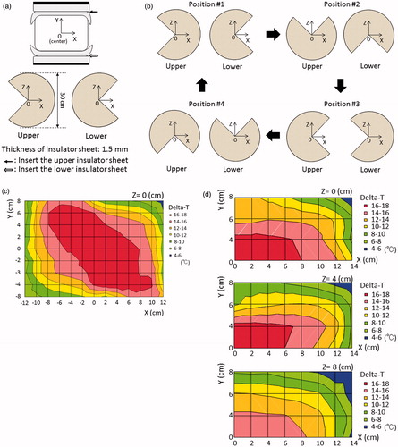
Silicone rubber sheets were selected as insulator sheets. The thickness of the silicone rubber was 0.5 mm, 1.0 mm or 1.5 mm (Inoac Corporation, Nagoya, Japan; volume resistivity value of 1015 Ω · cm). shows the conventional setting of the deep regional HT on the device; both the upper and lower electrodes with a regular bolus of 30 cm in diameter, overlay boluses cooled to 5 °C by the circulatory system, and an agar phantom. The centre of the agar phantom was defined as zero point of the X, Y and Z coordinates. Heating was performed under superficial cooling with overlay boluses. The base line temperature of the phantom was 24 degrees. The starting time between the cooling the overlay bolus and heating the phantom is simultaneous. The following three settings were applied when using the silicone rubber insulator sheet, in order to evaluate the temperature increase with deep regional HT. (1) Insulator sheets with a hole in the centre were inserted and attached to the front of both regular boluses (); the thickness of the silicone rubber was 0.5 mm or 1.0 mm. (2) Insulator sheets were inserted in a circular sector shape at an angle of 270° with an alternate arrangement and were attached to the front of both regular boluses (); the thickness of the silicone rubber was 1.5 mm. (3) The insulator sheets were used in the same manner as in setting number 2, with the exception that the regular boluses attached with the insulator sheet were manually rotated in parallel at an angle of 90° at 5-min interval during heating (); this setting was defined as the mobile insulator sheets setting. The required time for the rotation was less than 5 s. Sono Jelly (Toshiba Medical Supply Co., Ltd., Tokyo, Japan), which is generally applied for ultrasound visualisation, was applied to a surface of the overlay and regular boluses to avoid the air capsulation and contact failure. Because the 8 MHz capacitive heating device is open gantry system, the operator who took a kneeling position could rotate easily the insulator sheets. Patients did not need to get off the treatment table during the rotation of the insulator sheets. Each heating session was performed under a heating current at 7.5 A for 20 min. The output power and reflected power were adjusted as follows to maintain the heating current at 7.5 A: 1350 W and 50 W in the conventional setting, 1480 W and 160 W in setting number 1 with 0.5-mm-thick insulator sheets, 1560 W and 270 W in setting number 1 with 1.0-mm-thick insulator sheets, and 1610 W and 330 W in setting numbers 2 and 3.
Figure 1. (a) Pattern diagrams of the conventional setting in the phantom study. (b) The distributions of the temperature increase in the phantom for the conventional setting. The superficial area was cooled by the overlay bolus, while the deep area was uniformly heated (with the exception of the external border).
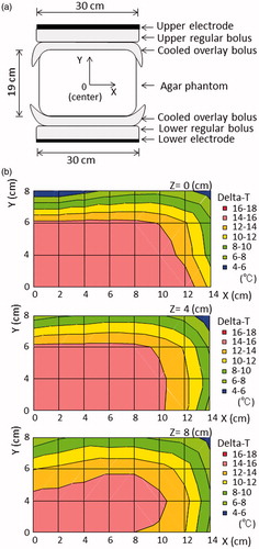
Figure 2. (a) Pattern diagrams of the insulator sheet with a hole in the centre, defined as setting number 1. The insulator sheet was inserted between the regular bolus and the cooled overlay bolus in both the upper and lower sides of the electrode. (b) The distribution of the temperature increase in the phantom with setting number 1.
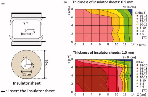
Figure 3. (a) Pattern diagrams in the phantom for setting number 2. The insulator sheets were alternately arranged in a circular sector shape at an angle of 270° and were inserted between the regular bolus and cooled overlay bolus in both the upper and lower sides of the electrode. (b) Pattern diagrams of setting number 3 in which mobile insulator sheets were used. The insulator sheets, which were prepared in a circular sector shape, the same as in setting number 2, were manually rotated in parallel at an angle of 90° at 5 min intervals during heating. (c) The distribution of the temperature increase with setting number 2. (d) The distributions of the temperature increase in setting number 3 in which mobile insulator sheets were used.
3D simulations for specific absorption rate in conventional heating and heating with silicone rubber sheets
SAR distributions were computed using the low-frequency (LF) solver of SIM4LIFE (version 3.2, ZMT, Zurich, Switzerland) [Citation30]. The LF-solver used a finite-element method (FEM). Each simulation set-up for the agar phantom and 3 D patient model was based on the conventional setting, setting number 1 with 0.5-mm-thick insulator sheets, or setting number 3 at each position. The 3 D patient model was reconstructed with a computed tomography (CT) data set comprising 71 slices with a slice thickness of 5 mm using the Medical Image Segmentation Tool Set (iSEG, ZMT, Zurich, Switzerland). Muscle, fat, bone and prostate were taken into account to generate the 3 D patient model. Furthermore, the subcutaneous fat (SF) was segmented and divided into eight parts by ventrodorsal, left and right, and craniocaudal directions relative to a centre of the heating area. The frequency was applied at 8 MHz. shows the electric conductivity (S/m), relative permittivity and mass density (kg/m3) used for the simulations. The values for the agar phantom were previously reported [Citation29]. The size of each model in the simulation was as follows: 23 megacells in the conventional setting and setting number 3 with 1.5-mm-thick insulator sheets, and 50 megacells in setting number 1 with 0.5-mm-thick insulator sheets. The average SAR of the prostate (as a heating target) of all positions in setting number 3 using a constant potential of 166.7 V was nearly equal to that of the prostate in the conventional setting using 117 V. Therefore, we decided to use these two constant potentials in order to evaluate the difference in the SAR of the SF under the equivalent SAR of the prostate among the different heating methods. The Mann–Whitney U-test was used to evaluate the differences in the SF/prostate ratio for averaged SARs among the conventional setting, setting number 1 and setting number 3.
Table 1. Dielectric and materials properties used for the simulations at 8 MHz.
The prospective clinical study
A prospective clinical study was planned based on setting number 1 (using 0.5-mm silicone rubber sheets) and setting number 3 of the phantom study. During definitive RT for prostate cancer, five deep regional HT treatment sessions were scheduled once weekly (one time/week). Conventional heating was performed during the first, third and fifth treatment sessions. Heating with the insulator sheets using setting numbers 1 or 3 was performed during the second and fourth treatment sessions. The eligibility criteria were as follows: an ECOG Performance Status of 0–1, normal liver and renal functions, no pacemaker implantation, no haematological disorders, the presence of prostate carcinoma that could be treated with definitive RT with deep regional HT using an 8 MHz radiofrequency capacitive heating device, and cases in which the intra-rectal temperature could be measured. These tumours were selected for the clinical prospective trial for the following reasons: they were located in the centre of the cross section of the pelvis, where it was hypothesised that a favourable increase in temperature could be achieved (based on the results of the phantom study); and because the intra-rectal temperature was easily monitored and was highly correlated with the tumour temperature [Citation31,Citation32]. The protocol of the clinical prospective study was approved by the Institutional Review Board of our institution. Written informed consent for the clinical prospective study was obtained from all of the patients.
Definitive RT was planned conventionally, with treatments performed once daily five times/week using a 10-MV linear accelerator. The centre of the heating area was fitted to the cutaneous markings of the RT-isocentre, which was located at the centre of the prostate. The treatment posture for all cases was the prone position. The patients were carefully instructed to alert the operator of any unpleasant sensations, such as pain suggestive of a hot spot, respiratory problems or palpitation. The RF-output was increased to the maximum level tolerated by the patients, following the appropriate adjustments of the treatment setting, and the patient's tolerance threshold was established based on their response. The goal was to continue the treatment for 50 min. In the sessions in which setting number 3 (mobile insulator sheets) was applied, regular boluses attached to the insulator sheet were manually rotated in parallel at an angle of 90° at 5-min interval; if subcutaneous pain near the non-insulated area emerged, the regular boluses attached to the insulator sheet could be rotated earlier.
The intra-rectal temperature was measured using a 4-point micro-thermocouple sensor (Yamamoto Vinita, LAS-4, Osaka, Japan) which was inserted into the rectum, at the level of the prostate. The temperature was automatically recorded each minute during HT. The Tx is an index temperature, indicating when the temperature was reached or exceeded by x% of the intra-rectal measurement points. The CEM43°CT90 has been used extensively and successfully in clinical trials to assess the efficacy of heating [Citation14,Citation33–36] and represents the thermal isoeffect dose expressed in cumulative equivalent minutes at a reference temperature of 43 °C, based on the low end of the temperature distribution (T90), and was calculated from the time-temperature data using the following formula:
When the temperature is higher than 43 °C, R = 0.5. When the temperature is lower than 43 °C, R = 0.25. In this protocol, ti was the time interval of the ith sample (ti = 1.0 min). The temperature exceeding the temperature at 90% of the intra-rectal measurement points during the ith minute was designated as T90i. We then used the CEM43°CT90 to convert each T90i into an equivalent time at 43 °C and then to calculate the sum of these equivalent times over the entire treatment duration of n minutes. The Mann–Whitney U-test was used to evaluate differences in thermal parameters among the sessions with the conventional setting, the setting number 1 and the setting number 3.
The toxicity of therapy was evaluated according to the Common Terminology Criteria for Adverse Events version 3.0. The highest toxicity for each patient during and after RT with HT was entered into the toxicity analysis. Toxicity was defined as either acute (occurring during therapy or up to 3 months after therapy) or late (occurring more than 3 months after the completion of therapy).
Results
The distribution in the increase in temperature in the phantom study after heating using the conventional setting is shown in . Most areas in the phantom were uniformly heated, with the exception of the superficial area (Y ≥ 6 cm), which was cooled by the overlaying bolus, and the outside edge (X ≥ 8 cm). shows the distribution of the temperature increases using setting number 1. When 0.5-mm-thick insulator sheets were applied, the area in which a greater temperature increase occurred narrowed towards the centre of the X-axis. On the other hand, the area with a greater temperature increase was broadened towards the Y-axis until the superficial area, despite the superficial area was under superficial cooling. When 1.0-mm-thick insulator sheets were used, the temperature gradient was more prominent than that observed with the 0.5-mm-thick insulator sheets. shows the distribution of the temperature increases using setting number 2. The area with a greater temperature increase was wider towards the non-insulated area, which was not covered by the insulator sheet on the electrode, while the lower heating area was wider toward the insulated area on the electrode. shows the distributions of the temperature increases using setting number 3, in which mobile insulator sheets were used. The greater heating area improved in a direction towards the centre on the X-axis (≤6 cm), Y (≤4 cm) and the Z-axis (≤4 cm). SAR distributions using the numerical 3 D simulations in the conventional setting, setting number 1 and setting number 2 which is the same as setting number 3 at each position are shown in . The SAR distributions for each setting in the agar phantom using the numerical 3 D simulations were generally consistent with the temperature distribution, except for the high-SAR regions in the superficial areas, which were cooled by overlay boluses.
Figure 4. (a) Pattern diagrams for the 3 D SAR simulation using the agar phantom. (b) SAR distribution in the phantom for the conventional setting. (c) SAR distribution in the setting number 1. (d) SAR distribution in the setting number 1 at an oblique angle. (e) SAR distribution in setting number 3 at position #1. (f) SAR distribution in setting number 3 at position #1 at an oblique angle.
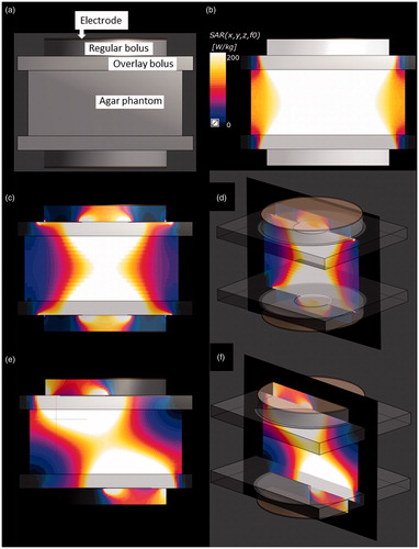
The SAR distributions using the 3 D anatomical model in the conventional setting and settings number 1 and 3 are shown in . In the conventional setting, the SF areas where the overlay bolus made contact consistently showed a high SAR (). In setting number 1, the SF areas in which a greater SAR increase occurred showed modest narrowing towards the centre of the electrode compared with those in the conventional setting. However, most of the SF area where the overlay bolus made contact still showed high SAR (). In setting number 3, the SAR increase was well suppressed in the area where covered by the insulator sheets, while the areas with high SAR were located in the SF areas not covered by the insulator sheets ().
Figure 5. (a) Segmented CT slice of the caudal area showing the bone (blue), muscle (yellowish green), prostate (red) and subcutaneous fat (SF) of the right ventral area (pink), left ventral area (white), right dorsal area (orange), left dorsal area (green) and other fat (yellow). (b) Colour scale bar of the SAR distribution. (c) SAR distribution in the 3 D anatomical model for the conventional setting. Constant potential was set at 117 V. (d) Sagittal view of the SAR distribution in the conventional setting. (e) SAR distribution in setting number 1. Constant potential was set at 166.7 V. (f) Sagittal view of the SAR distribution in setting number 1. (g) SAR distribution in setting number 3 at position #1. Constant potential was set at 166.7 V for setting number 3. (h) Sagittal view of the SAR distribution in setting number 3 at position #2. (i) SAR distribution in setting number 3 at position #3. (j) Sagittal view of the SAR distribution in setting number 3 at position #4.
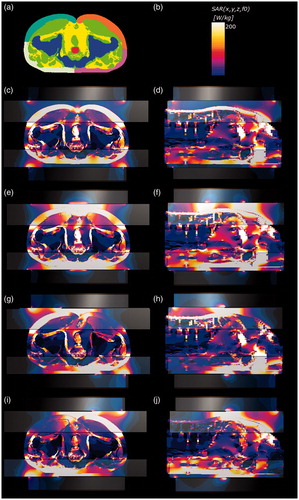
shows the results of the 3 D SAR simulations using the 3 D patient model. In setting number 3, the average and maximum local SAR of the insulated SF area was selectively reduced in each position of the mobile insulator sheets, while the average SARs of the prostate as the heating target were maintained. The average SF/target ratios (median, 2.5; range, 2.1–2.6.) among 4 positions for the average SAR in setting number 3 were significantly lower than the SF/target ratios (median, 3.4; range, 2.5–4.0) in the conventional setting (p = .0063) (). The SF/target ratios (median, 2.9; range, 2.4–3.2) for the average SARs in setting number 1 tended to be lower than those (median, 3.4; range, 2.5–4.0) in the conventional setting (p = .066), albeit not to a significant degree ().
Table 2. Three-dimensional SAR simulations using the 3 D patient model.
In the clinical prospective study, which was performed at our institution between June 2012 and October 2012, 10 patients (median age, 70 years; range, 61–78 years) with prostate cancer were eligible for the setting number 1 (with the 0.5-mm-thick insulator sheets). Between December 2012 and April 2013, nine patients (median age, 72 years; range, 62–77 years) with prostate cancer (n = 9) were eligible for the setting number 3 (in which mobile insulator sheets were used). For setting number 1, nine (90%) of the 10 patients could complete the planned five HT sessions. The remaining patient refused to undergo the fourth and fifth HT sessions. All 10 patients could receive the planned definitive RT. shows the results of the thermal parameters in the HT sessions with conventional settings and those with setting number 1. There were no significant difference between the conventional settings and setting number 1 with regard to the heating duration and the thermal parameters; the thermal dose of median CEM43°CT90 in the conventional setting and setting number 1 was 1.2 min and 1.6 min, respectively, showing no significant difference. For setting number 3, eight (89%) of the nine patients could complete the planned five HT sessions. The remaining one patient refused to receive the fourth and fifth HT sessions. All nine patients could receive the planned definitive RT. shows that all of the thermal parameters in the sessions in which setting number 3 was used were significantly better in comparison to those in the sessions in which the conventional setting was used; the thermal dose of median CEM43°CT90 increased from 1.0 min to 1.9 min. The averaged differences and comparison of the thermal parameters among order of the HT sessions in setting number 3 are indicated in . There was no significant difference in the duration of heating using the conventional setting and that using setting number 3. The acute toxicities that occurred in the whole study population (n = 21) were as follows: Grade 3 leukopenia (n = 1), Grade 3 anaemia (n = 1), Grade 2 genitourinary (GU) toxicity (n = 6, 29%), Grade 1 GU (n = 4, 19%), Grade 1 gastrointestinal (n = 2, 1%). Skin burn presenting as subcutaneous induration was observed in five patients (23%), but spontaneously resolved after the completion of regional HT. No late toxicity ≥ Grade 2 was observed.
Table 3. The thermal parameters in the HT sessions with the conventional setting and with setting number 1 (insulator sheets with a hole in the centre).
Table 4. the thermal parameters in HT sessions with the conventional setting and with setting number 3 (using mobile insulator sheets).
Table 5. Comparisons of the thermal parameters in setting number 3 (using mobile insulator sheets) by the order of the HT sessions.
Discussion
This is the first report to show that mobile insulator sheets have a potential to optimise the distribution of the deep heating area and achieve a greater temperature increase at the central heating target using an 8 MHz radiofrequency capacitive heating device. This method is feasible and promising because the insertion of the mobile insulator sheets in the current device is a simple method that does not involve the major reconstruction of the heating device. As mentioned in the introduction, a significant disadvantage of RF capacitive devices is their preferential heating of the subcutaneous fat tissue [Citation37,Citation38]. Because the depth at which the bolus can cool the subcutaneous fat tissue is limited, the thinner subcutaneous fat is a significant predictor of the achievement of a good temperature increase of deep-seated tumours [Citation39–42]. Several previous reports have investigated methods of improving the efficacy of RF capacitive devices in deep regional heating [Citation21,Citation38,Citation40,Citation43,Citation44]. Thermoesthesia near the electrode edge can be reduced using an overlay bolus, which is applied (in addition to the regular bolus) to minimise the contact between the electrode edge and the body surface [Citation45,Citation46]. Strong superficial cooling using an overlay bolus, where the liquid close to the freezing point of water is circulated, can suppress the preferential heating of the subcutaneous fat tissue [Citation38,Citation40]. Rhee et al. showed the usefulness of precooling the subcutaneous fat tissue in deep regional HT using an RF capacitive device [Citation47]. Tomimatsu et al. demonstrated a refinement of the circulating liquid of the overlay bolus, and a substantial temperature increase in deep regions was possible when 0.5% NaCl was used as the overlay bolus circulating liquid [Citation44]. Imada et al. showed that heating in a prone position allows for a higher RF output elevation and diminishes the degree of thermoesthesia in deep regional HT for deep-seated intrathoracic tumours in comparison to the supine position [Citation43].
Recently, however, Yahara et al. reported the clinical experience in prostate cancer patients treated with RT plus deep regional HT using a capacitive device in which a lower CEM43°CT90 was observed in 35 (47%) of 75 patients, despite heating being performed using strong superficial cooling, an overlay bolus with the refinement of the circulating liquid and the patient in the prone position [Citation42]. In the current study, we demonstrated that the novel method using mobile insulator sheets achieved significant improvements in the thermal parameters in comparison to the conventional setting, which included strong superficial cooling, an overlay bolus the refinement of the circulating liquid and the prone position. Based on these results, we consider the present method to be promising and suggest that it should be selected preferentially for patients in whom higher thermal parameters cannot be achieved using the conventional setting. In the phantom study, the insulator sheets with a off-centre round hole (the setting number 1) led to greater temperature increases in superficial central area, which could not be cooled by superficial cooling using overlay boluses in the phantom study. When 1.0-mm-thick insulator sheets with a off-centre round hole were used, the temperature gradient was more prominent than that observed with the 0.5-mm-thick insulator sheets with a off-centre round hole. Therefore, we judged that more than 0.5-mm-thick insulator sheets with off-centre round hole, which would lead to much greater temperature increases in superficial central area, cannot clinically be used. The 1.5-mm-thick sheets in a circular sector shape (the setting number 2) consequently led to greater temperature increases in superficial un-insulated area, which also could not be cooled by superficial cooling in the phantom study. However, the steering sheet (the setting number 3) could temporally shift the area of greater temperature increases in superficial area and could inhibit the temperature increases in the superficial area. The simulation results using the 3 D patient model demonstrated that the SAR of the insulated SF area was selectively reduced in each position of the steering insulator sheets, while the SARs of the heating target were maintained. The SF/target ratios for the average SARs in the setting with the mobile insulator were significantly improved compared with those in the conventional setting. In the clinical prospective study, we confirmed that this method of the steering sheet (the setting number 3) could achieve a significant increase in the thermal parameters of patients with prostate in comparison to conventional heating. We are of the opinion that this is a promising strategy for optimising the deep heating area in this device. On the other hand, the use of static setting number 1 with the 0.5-mm-thick insulator sheets with off-centre round hole did not result in a significant increase in the patients’ thermal parameters in the clinical prospective study. We hypothesise that the main reason for the higher temperature increase in the superficial area, which results in pain, was that it occurred easily, even under superficial cooling in setting number 1.
HT treatment planning (HTP) has recently been investigated, with the aim of simulating temperature patterns as well as SAR distributions and helping the operators visualise the effects of different steering strategies in modern locoregional radiofrequency HT treatments [Citation48,Citation49]. Further investigations using modern electromagnetic and thermal simulation techniques may be useful for optimising the temperature distribution with a high degree of accuracy using current heating methods with mobile insulator sheets.
Achieving sufficiently high tumour temperatures is very important for ensuring a good clinical outcome. Meta-analyses to investigate the thermal parameters among the four Phase III clinical trials showed that RT plus superficial HT using higher tumour temperatures had significantly better local control rates; on the other hand, the local control rate of RT plus superficial HT using lower tumour temperatures was almost the same as that of RT alone [Citation17]. Yahara et al. also showed that the addition of HT with higher thermal parameters to RT may improve biochemical disease-free survival in patients with high-risk prostate cancer. In contrast, there was no difference in the biochemical disease-free survival of the patients with lower thermal parameters and those who were treated with RT alone [Citation42]. These clinical data clearly demonstrated that a higher tumour temperature is required to enhance the RT effect in accordance with the results of in vitro/in vivo studies [Citation5,Citation12]. Thus, our current methods using the mobile insulator sheets to achieve a higher tumour temperature may be useful for improving the treatment results of combination therapy with RT plus deep regional HT.
In summary, this is the first study to assess the effects of mobile insulator sheets in the optimisation of the deep heating area in regional HT using a capacitively coupled heating method. In the phantom study, the novel deep heating method could improve the temperature in the central target area. The mobile insulator sheets were able to improve the SF/target ratios for the average SAR in the numerical simulation. In the prospective clinical study, the novel methods using the mobile insulator sheets was feasible and allowed deep regional HT to be performed with higher thermal parameters in patients with prostate cancer. Our proposed methods do not require complex technology, are low cost and can be applied uniformly among institutions using the 8-MHz radiofrequency-capacitive device. Further investigations, including studies involving modern HTP are justified to improve this heating method.
Acknowledgements
The authors thank Hirokazu Kato, Graduate School of Health Sciences, Okayama University, for his advice and scientific discussion, and Yumi Tanaka, Department of Radiology, University of Occupational and Environmental Health for her technical support.
Disclosure statement
No potential conflict of interest was reported by the authors.
Additional information
Funding
References
- Datta NR, Ordonez SG, Gaipl US, et al. (2015). Local hyperthermia combined with radiotherapy and-/or chemotherapy: recent advances and promises for the future. Cancer Treat Rev 41:742–53.
- van der Zee J, Gonzalez Gonzalez D, van Rhoon GC, et al. (2000). Comparison of radiotherapy alone with radiotherapy plus hyperthermia in locally advanced pelvic tumours: a prospective, randomised, multicentre trial. Dutch Deep Hyperthermia Group. Lancet 355:1119–25.
- Harima Y, Nagata K, Harima K, et al. (2001). A randomized clinical trial of radiation therapy versus thermoradiotherapy in stage IIIB cervical carcinoma. Int J Hyperthermia 17:97–105.
- Overgaard J, Gonzalez DG, Hulshof MC, et al. (1996). Hyperthermia as an adjuvant to radiation therapy of recurrent or metastatic malignant melanoma. A multicentre randomized trial by the European Society for Hyperthermic Oncology. Int J Hyperthermia 12:3–20.
- Jones EL, Samulski TV, Vujaskovic Z, et al. Hyperthermia, principles and practice of radiation oncology. 4th ed. Philadelphia: Lippincott Williams & Wilkins, 2003.
- Harima Y, Ohguri T, Imada H, et al. (2016). A multicenter randomized clinical trial of chemoradiotherapy plus hyperthermia versus chemoradiotherapy alone in patients with locally advanced cervical cancer. Int J Hyperthermia 32:801–8.
- Ben-Hur E, Elkind MM. (1974). Thermally enhanced radioresponse of cultured Chinese hamster cells: damage and repair of single-stranded DNA and a DNA complex. Radiat Res 59:484–95.
- Krawczyk PM, Eppink B, Essers J, et al. (2011). Mild hyperthermia inhibits homologous recombination, induces BRCA2 degradation, and sensitizes cancer cells to poly (ADP-ribose) polymerase-1 inhibition. Proc Natl Acad Sci USA 108:9851–6.
- Issels R, Kampmann E, Kanaar R, Lindner LH. (2016). Hallmarks of hyperthermia in driving the future of clinical hyperthermia as targeted therapy: translation into clinical application. Int J Hyperthermia 32:89–95.
- Oei AL, Vriend LE, Crezee J, et al. (2015). Effects of hyperthermia on DNA repair pathways: one treatment to inhibit them all. Radiat Oncol 10:165.
- Horsman MR, Overgaard J. (2007). Hyperthermia: a potent enhancer of radiotherapy. Clin Oncol (R Coll Radiol) 19:418–26.
- Dewey WC, Hopwood LE, Sapareto SA, Gerweck LE. (1977). Cellular responses to combinations of hyperthermia and radiation. Radiology 123:463–74.
- Sapareto SA, Hopwood LE, Dewey WC. (1978). Combined effects of X irradiation and hyperthermia on CHO cells for various temperatures and orders of application. Radiat Res 73:221–33.
- van Rhoon GC. (2016). Is CEM43 still a relevant thermal dose parameter for hyperthermia treatment monitoring?. Int J Hyperthermia 32:50–62.
- Franckena M, Fatehi D, de Bruijne M, et al. (2009). Hyperthermia dose-effect relationship in 420 patients with cervical cancer treated with combined radiotherapy and hyperthermia. Eur J Cancer 45:1969–78.
- Ohguri T, Harima Y, Imada H, et al. (2017). Relationships between thermal dose parameters and the efficacy of definitive chemoradiotherapy plus regional hyperthermia in the treatment of locally advanced cervical cancer: data from a multicentre randomised clinical trial. Int J Hyperthermia [Epub ahead of print]. doi: 10.1080/02656736.2017.1352105
- Sherar M, Liu FF, Pintilie M, et al. (1997). Relationship between thermal dose and outcome in thermoradiotherapy treatments for superficial recurrences of breast cancer: data from a phase III trial. Int J Radiat Oncol Biol Phys 39:371–80.
- Bruggmoser G, Bauchowitz S, Canters R, et al. (2011). Quality assurance for clinical studies in regional deep hyperthermia. Strahlenther Onkol 187:605–10.
- Tanaka Y, Imada H, Hiraki Y, et al. (2007). The past and present status of clinical hyperthermia in Japan: a survey in 2004 using a questionnaire. Thermal Medicine 23:1–10.
- van Rhoon GC, van der Zee J, Broekmeyer-Reurink MP, et al. (1992). Radiofrequency capacitive heating of deep-seated tumours using pre-cooling of the subcutaneous tissues: results on thermometry in Dutch patients. Int J Hyperthermia 8:843–54.
- Song CW, Rhee JG, Lee CK, Levitt SH. (1986). Capacitive heating of phantom and human tumors with an 8 MHz radiofrequency applicator (Thermotron RF-8). Int J Radiat Oncol Biol Phys 12:365–72.
- Takayama N, Okumura Y, Kimura T, et al. Applicator for hyperthermia. Kokai Jitsuyo Shinan Koho 1989; #20858.
- Narabayashi I, Kawai T, Tatsumi T, Yachi K, Applicator for hyperthermia. Japan Patent Kokai 1993; #115561.
- Abe M, Hiraoka M, Takahashi M, et al. (1986). Multi-institutional studies on hyperthermia using an 8-MHz radiofrequency capacitive heating device (Thermotron RF-8) in combination with radiation for cancer therapy. Cancer 58:1589–95.
- Hiraoka M, Jo S, Akuta K, et al. (1987). Radiofrequency capacitive hyperthermia for deep-seated tumors. II. Effects of thermoradiotherapy. Cancer 60:128–35.
- Izukura R, Imada H, Hashiguchi N, et al. (2017). Cardiac and respiratory effects of deep regional hyperthermia using an 8-MHz radiofrequency-capacitive device on patients with cancer. Int J Hyperthermia 33:428–34.
- Reddy NM, Balakrishnan IS, Bhaskar BK, et al. (1986). Optimization of power deposition and the rate of heating of tissue during RF capacitive hyperthermia. Int J Hyperthermia 2:321.
- Brezovich IA, Lilly MB, Durant JR, Richards DB. (1981). A practical system for clinical radiofrequency hyperthermia. Int J Radiat Oncol Biol Phys 7:423–30.
- Kato H, Hiraoka M, Ishida T. (1986). An agar phantom for hyperthermia. Med Phys 13:396–8.
- Modeling for device design and personalized treatment planning. Sim4Life by ZMT. Available from: http://www.zurichmedtech.com/applications/thermal-therapies/ (2014). [last accessed 27 Jan 2017].
- van der Zee J, Peer-Valstar JN, Rietveld PJ, et al. (1998). Practical limitations of interstitial thermometry during deep hyperthermia. Int J Radiat Oncol Biol Phys 40:1205–12.
- Fatehi D, van der Zee J, Notenboom A, van Rhoon GC. (2007). Comparison of intratumor and intraluminal temperatures during locoregional deep hyperthermia of pelvic tumors. Strahlenther Onkol 183:479–86.
- Oleson JR, Samulski TV, Leopold KA, et al. (1993). Sensitivity of hyperthermia trial outcomes to temperature and time: implications for thermal goals of treatment. Int J Radiat Oncol Biol Phys 25:289–97.
- Jones EL, Oleson JR, Prosnitz LR, et al. (2005). Randomized trial of hyperthermia and radiation for superficial tumors. J Clin Oncol 23:3079–85.
- Dewhirst MW, Viglianti BL, Lora-Michiels M, et al. (2003). Basic principles of thermal dosimetry and thermal thresholds for tissue damage from hyperthermia. Int J Hyperthermia 19:267–94.
- Trefna HD, Crezee H, Schmidt M, et al. (2017). Quality assurance guidelines for superficial hyperthermia clinical trials: I. Clinical requirements. Int J Hyperthermia 33:471–82.
- van der Zee J, Vujaskovic Z, Kondo M, Sugahara T. (2008). The Kadota Fund International Forum 2004-clinical group consensus. Int J Hyperthermia 24:111–22.
- Ohguri T, Imada H, Yahara K, et al. (2004). Effect of 8-MHz radiofrequency-capacitive regional hyperthermia with strong superficial cooling for unresectable or recurrent colorectal cancer. Int J Hyperthermia 20:465–75.
- Kroeze H, van de Kamer JB, de Leeuw AA, et al. (2003). Treatment planning for capacitive regional hyperthermia. Int J Hyperthermia 19:58–73.
- Tomimatsu A, Imada H, Kosaka K, et al. (1999). Advantage of an external cooling unit in deep hyperthermia using an 8 MHz RF capacitive heating device. Jpn J Hyperthermic Oncol 15:65–70.
- Ohguri T, Yahara K, Moon SD, et al. (2011). Deep regional hyperthermia for the whole thoracic region using 8 MHz radiofrequency-capacitive heating device: relationship between the radiofrequency-output power and the intra-oesophageal temperature and predictive factors for a good heating in 59 patients. Int J Hyperthermia 27:20–6.
- Yahara K, Ohguri T, Yamaguchi S, et al. (2015). Definitive radiotherapy plus regional hyperthermia for high-risk and very high-risk prostate carcinoma: Thermal parameters correlated with biochemical relapse-free survival. Int J Hyperthermia 31:600–8.
- Imada T, Nomoto S, Tomimatsu A, et al. (1999). Importance of patient positioning in hyperthermia for deep-seated intrathoracic tumors using an 8 MHz RF capacitive heating device. Jpn J Hyperthermic Oncol 15:15–9.
- Tomimatsu A, Imada H, Kosaka K, et al. (1999). Refinement of circulating liquid of overlay bolus in hyperthermia using an 8 MHz RF capacitive heating device. Jpn J Hyperthermic Oncol 15:71–7.
- Yanagawa S, Sone Y, Doi H, Yamamoto G. (1985). A new procedure for the prevention of surface overheating in deep hyperthermia using RF capacitive heating equipment. Jpn J Hyperthermic Oncol 1:187–91.
- Karasawa K, Muta N, Nakagawa K, et al. (1994). Thermoradiotherapy in the treatment of locally advanced nonsmall cell lung cancer. Int J Radiat Oncol Biol Phys 30:1171–7.
- Rhee JG, Lee CK, Osborn J, et al. (1991). Precooling prevents overheating of subcutaneous fat in the use of RF capacitive heating. Int J Radiat Oncol Biol Phys 20:1009–15.
- Kok HP, Wust P, Stauffer PR, et al. (2015). Current state of the art of regional hyperthermia treatment planning: a review. Radiat Oncol 10:196.
- Canters RA, Paulides MM, Franckena MF, et al. (2012). Implementation of treatment planning in the routine clinical procedure of regional hyperthermia treatment of cervical cancer: an overview and the Rotterdam experience. Int J Hyperthermia 28:570–81.