
 ?Mathematical formulae have been encoded as MathML and are displayed in this HTML version using MathJax in order to improve their display. Uncheck the box to turn MathJax off. This feature requires Javascript. Click on a formula to zoom.
Abstract
Purpose: Although bipolar radiofrequency (RF) ablation (RFA) is broadly used to eliminate ventricular tachycardias in the interventricular septum wall, it can fail to create transmural lesions in thick ventricular walls. To solve this problem, we explored whether an RF-energised guidewire inserted into the ventricular wall would enhance bipolar RFA in the creation of transmural lesions through the ventricular wall.
Methods: We built three-dimensional computational models including two irrigated electrodes placed on opposing sides of the interventricular septum and a metal guidewire inserted into the septum. Computer simulations were conducted to compare the temperature distributions obtained with two ablation modes: bipolar mode (RF power delivered between both irrigated electrode) and time-division multiplexing (TDM) technique, which consists of activating the bipolar mode for 90% of the time and applying RF power between the guidewire and both irrigated electrodes during the remaining time.
Results: The TDM technique was the most suitable in terms of creating wider lesions through the entire ventricular wall, avoiding the hour-glass shape of thermal lesions associated with the bipolar mode. This was especially apparent in the case of thick walls (15 mm). Furthermore, the TDM technique was able to create transmural lesions even when the guidewire was displaced from the midplane of the wall.
Conclusions: An RF-energised guidewire could enhance bipolar RFA by allowing transmural lesions to be made through thick ventricular walls. However, the safety of this new approach must be assessed in future pre-clinical studies, especially in terms of the risk of stenosis and its clinical impact.
Introduction
In the context of the ablation of resistant ventricular tachycardia (VT), where the re-entrant circuits causing the arrhythmia can be located in deep intramural sites, bipolar radiofrequency (RF) ablation (RFA) by two ablation catheters positioned on each side of the interventricular wall has been proposed as an alternative when sequential unipolar application fails to reach intramural circuits [Citation1–3]. However, bipolar RFA represents progress in the way RF power is used in these cases, it may not be the final answer, as the two ablation catheters are frequently seated more than 15 mm from each other, reducing the potential advantages of bipolar application.
Interestingly, the interventricular wall has septal branches running approximately across the middle of the septum, all which would be less than 10 mm from each side of the septal wall. With the goal of creating thermal lesions deep enough to reach any target in deep intramural sites, we hypothesised that bipolar RF ablation could be enhanced by placing a metal guidewire (0.014-inch diameter) inside these branches to potentially serve as an RF electrode, i.e. it would become RF-energised. The idea here would hence be to treat the origin of the intramural VT directly, next to the coronary vessels, just where the inaccessibility of the epicardial/endocardial approaches the limit of successful RF ablation [Citation4].
The idea of applying RF power through a 0.035 inch endovascular RF wire (PowerWire, Baylis Medical, Montreal, Canada) placed in the interventricular septum has already been clinically proven using 10 W of power for 4 s in a monopolar mode [Citation5]. It is known that the application of RF power through a metal wire buried in the tissue has a risk of overheating, steam popping and carbonisation due to the high current density at the wire-tissue interface [Citation6]. However, if the applied RF power is correctly chosen, it is possible to create optimal and safe thermal lesions. In any case, the created thermal lesions are generally very small and completely circumscribed around the wire.
Keeping these characteristics in mind, in order to achieve a transmural thermal lesion, i.e. occupying the entire ventricular wall, we proposed that an RF-energised intracoronary guidewire could be employed along with two irrigated-tip electrodes positioned on each side of the interventricular wall. As shown in , the guidewire inserted into a septal coronary branch at approximately mid-distance from the two irrigated-tip electrodes. We also proposed to combine sequentially two modes of applying RF power: (1) bipolar mode: between both conventional electrodes while the metallic segment of the guide-wire is not RF-energised and (2) guide mode: between the guidewire (which would act as an active electrode) and the conventional electrodes (which would serve as dispersive electrodes).
Figure 1. Physical arrangement for the proposed technique showing two ablation catheters positioned on opposing sides of the interventricular septum and a guidewire inserted into a septal coronary branch. The switching controller can implement the time-division multiplexing (TDM) technique, which consists of activating the bipolar mode for a relatively long fraction of time (A) and RF-energised guidewire in the remaining time (B).
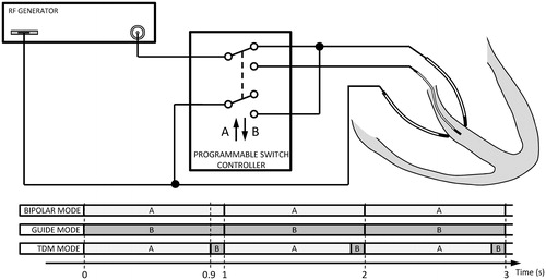
Specifically, we proposed the use of a time-division multiplexing (TDM) technique consisting of activating the bipolar mode for a fraction of the time and an RF-energised guidewire for the remaining time of the repetition period. Our goal was to study the efficacy of this technique by computer simulations in terms of creating transmural lesions on the septal wall and then compare it with the bipolar mode.
Materials and methods
Description of the physical situation and computational model
shows the physical study set-up, which consists of an interventricular septum ablation using two irrigated-tip electrodes placed on opposing sides of the septal wall surface and an endovascular metallic guidewire (0.35 mm diameter) placed inside the septal wall. Both irrigated-tip electrodes and the guidewire could be connected to a programmable switch controller to allow selecting “bipolar”, “guide” and “time-division multiplexing” (TDM) ablation modes. The bipolar mode consists of applying energy between both irrigated-tip electrodes, one of which is active and the other dispersive, whereas the guidewire remains passive (non RF-energised). The guide mode consists of applying RF energy only, using the metal zone of the guidewire, while both irrigated-tip electrodes act as dispersive electrodes. Finally, TDM mode consists of combining bipolar and guide mode once a second. In TDM mode, the bipolar pattern is activated for a fraction of the time (90%) and the RF-energised guidewire for the remainder (10%) of each second. In this way the switching frequency between patterns is 1 Hz, i.e. in a given second the bipolar ablation is conducted for the first 900 ms and RF-energised guidewire in the remaining 100 ms.
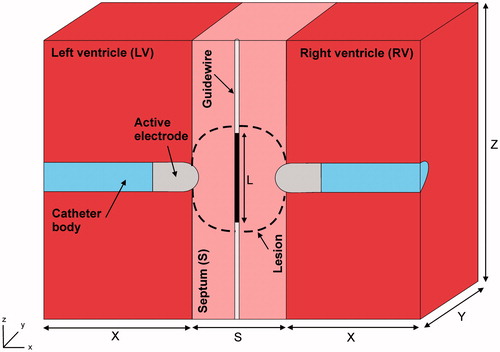
shows the geometry and dimensions of the three-dimensional computational model built, where the XZ-plane is the symmetry plane. The model consists of a ventricular septum with a metal guidewire placed in the middle. Two irrigated electrodes are placed perpendicularly to the septum wall surface (endocardium–endocardium approach) and surrounded by circulating blood (both ventricles). The irrigated electrodes (7 Fr in diameter and 3.5 mm long) are inserted into the tissue to a depth equal to one-third of their diameter (DE ∼0.8 mm). The guidewire has a metal part of length L. Ventricular septum thickness (S) is initially 12 mm, as most patients with septal VT have some degree of cardiomyopathy, which causes hypertrophy, in which septal thickness ranges between 9 and 12 mm or even up to 20 mm [Citation7]. The dimensions of ventricles (X, Y and Z) were estimated by a convergence test, in which the value of the maximal temperature achieved in the tissue (Tmax) after 60 s of RF heating was used as the control parameter. We first considered a tentative spatial (i.e. minimum meshing size) and temporal resolution. To determine the appropriate parameters (X, Y and Z), we increased their values by equal amounts. When the difference in the Tmax between consecutive simulations was less than 0.5%, the former values were considered to be adequate. We then determined the appropriate spatial and temporal resolution by means of similar convergence tests using the same control parameter as in the previous test. Discretisation was spatially heterogeneous: the finest zone was always the electrode-tissue interface, where the largest voltage gradient was produced and hence, the maximum value of current density. In the tissue, grid size was increased gradually with distance from the electrode-tissue interface.
Figure 2. Geometry of the three-dimensional computational model built (not to scale) consisting of a ventricular septum (thickness S) in which a metallic guidewire has been placed. RF current can be programmed to flow either in bipolar mode between a couple of irrigated-tip electrodes (7 Fr, 3.5 mm) or between a metal guidewire and the irrigated-tip electrodes. Dimensions of cardiac tissue and blood (X, Y and Z) were obtained from a convergence test.
Governing equations
The numerical models were based on a coupled electric-thermal problem which was solved numerically using the finite element method (FEM) with ANSYS software (ANSYS, Canonsburg, PA). The governing equation for the thermal problem was the Bioheat Equation [Citation8]:
(1)
(1)
where ρ is density (kg/m3), c is specific heat (J/kg·K), T is temperature (°C), t is time (s), k is thermal conductivity (W/m·K), q is the heat source caused by RF power (W/m3), Qp is the heat loss caused by blood perfusion (W/m3) and Qm is the metabolic heat generation (W/m3). Qp was not considered since its effect is expected to be minor [Citation9] and independent of the method used to model the saline irrigation and blood flow. Likewise, Qm was not considered because its effect is negligible in comparison to the other terms [Citation10].
At the frequencies used in RF heating (≈500 kHz) and over the distance of interest, the biological medium can be considered almost totally resistive, and a quasi-static approach can, therefore, be used to solve the electrical problem [Citation11]. The distributed heat source q is then given by q = σ|E|2, where |E| is the magnitude of the vector electric field (V/m) and σ the electrical conductivity (S/m). E = −∇Ф is calculated from the gradient of the voltage Φ (V), which, in absence of internal electric sources, satisfies ∇⋅(σ∇Ф) = 0.
Model properties and boundary conditions
The thermal and electrical properties of the model elements are shown in [Citation12]. The initial temperature of the entire model was 37 °C. The electrical conductivity (σ) of cardiac tissue was considered as a temperature-dependent function as follows: it rose linearly +1.6%/°C up to 100 °C, where 0.6 S/m was the value of the electrical conductivity assessed at 37 °C (see ), and then it decreased two orders for five degrees to model the tissue desiccation process [Citation13].
Table 1. Physical characteristics of tissues and materials employed in the computational models (data from Ref. [Citation12]).
shows the thermal and electrical boundary conditions. For the thermal boundary conditions (), a null thermal flux was used on the symmetry axis and a constant temperature of 37 °C was fixed on the outer surfaces of the model at a distance from the ablating electrodes (this was also the initial temperature value). The effect of blood circulating inside the ventricles was modelled by thermal convection coefficients at the electrode–blood (hE) and the tissue–blood (hT) interfaces, considering electrical conductivity of blood independent of temperature (as in Method 2 described by Ref. [Citation15]). These coefficients were calculated under conditions of high blood flow, this being hE = 3346 W/m2·K and hT = 610 W/m2·K [Citation14]. The irrigated electrode was modelled by fixing a temperature of 40 °C (as in clinical practice for irrigated electrodes [Citation15]) only in the cylindrical zone of the electrode tip, leaving the semispherical tip free, as in previous computational studies [Citation9,Citation12,Citation16]. This approximation for modelling an irrigated electrode is able to predict lesion depth and also the maximum temperature reached in the tissue at all times during ablation [Citation17].
Figure 3. Thermal (a) boundary conditions of the model. hE and hT are the thermal convection coefficients at the electrode–blood and the tissue–blood interfaces, respectively. Electrical boundary conditions for the bipolar (b) and guide (c) mode. The guide mode uses the guidewire as active electrode and both irrigated-tip electrodes as dispersive electrodes. The TDM mode is a combination of (b) and (c): RF energy is applied 90% of the time in bipolar mode and the rest of the time (10%) in guide mode.
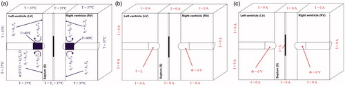
Regarding the electrical boundary conditions (), all the outer surfaces of the model and the symmetry plane were fixed to have zero electric flux (Neumann boundary condition). As in clinical practice with irrigated electrodes, a constant power ablation mode was used. The electrical current was adjusted by means of calculating the electrical impedance in each time-step in order to maintain the power at a constant value. Knowing the applied current and measuring the applied voltage at the ablating electrode, it is possible to calculate the impedance in each time-step. For the bipolar mode (), the power was applied at one of the electrodes and another was set to 0 V (dispersive electrode), so the electrical currents were forced to flow between both electrodes. Regarding the guide mode (), the power was applied through the guidewire and both electrodes were set to 0 V (dispersive electrodes). In this case, the electrical currents were forced to flow between the guidewire and both electrodes. And the TDM mode was a combination of both ablation modes: for 90% of the time, the power was applied in bipolar mode and the remaining time (10%) in guide mode per second.
Output variables
We studied the efficacy of the three different ablation modes in terms of creating transmural lesions through the septal wall after the ablation time (60 s). For this purpose, we conducted a series of simulations to study the effect on the temperature distributions and the thermal lesions created in the septal wall by changing the applied power, septal wall thickness, the size of the metallic guidewire, the guide mode (passive or active) and the displacement of the guidewire from the midpoint inside the septal wall (longitudinal or lateral displacement). Computer simulations were stopped when the maximal temperature in the tissue reached 100 °C. The thermal lesion shapes were identified by the 50 °C isotherm contour, as in previous studies [Citation9,Citation12,Citation14,Citation16,Citation17], which is usually considered to reasonably represent the isotherm of irreversible myocardial injury in hyperthermic ablation [Citation18].
Results
The convergence test provided the following optimal dimensions: X= (80 – S)/2 mm, Y = 22.5 mm and Z = 50 mm. The optimal grid size was of ∼80 µm in the finest zone (electrode–tissue interface and guidewire). The model had around 610 940 elements and 110 603 nodes. The time step was 0.2 s for bipolar and guide modes, and 0.1 s for the TDM mode.
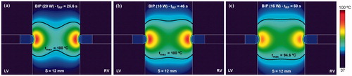
shows the temperature distributions and thermal lesion contour (black line) obtained in a 12 mm thickness ventricular septum after a bipolar RF ablation conducted exclusively with two ablation catheters placed on each endocardial side for three different power levels. The use of a high level of power (20 W) was associated with rapid overheating (temperature of 100 °C was reached at ∼25 s), when RF power immediately ceased and lesion geometry became hourglass-like. In contrast, a lower level of power (16 W) allowed RF power to be applied for the entire ablation duration (60 s) and lesion geometry was optimum in terms of lesion width in the middle zone. This lesion shape is expected to be more suitable to thermally destroy the abnormal electric circuit responsible for the VT, since it covers the entire wall beneath the RF electrodes. For this reason, from that point on, this power level was assumed to be optimum and was hence used in all the RF bipolar mode simulations.
Figure 4. Temperature distributions and thermal lesion contour (black line) in a 12 mm thickness ventricular septum without guidewire for three values of applied power (20, 18 and 16 W) in bipolar mode.
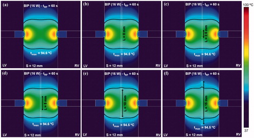
The next step was to assess distortions of the temperature distributions obtained in the ventricular septum with bipolar RF ablation due to the presence of a passive guidewire (i.e. non RF-energised). shows the temperature distributions and thermal lesion contours (black line) created in the septum for a 16 W bipolar RF ablation. It was noted that whatever the length of the metal zone of the guidewire, the effect of its presence was almost negligible in terms of temperature distributions. The thermal lesion in the middle zone was slightly extended on the guidewire surface only with a very long metal zone (>10 mm), probably due to the thermal conductivity of the metal being higher than the tissue. No electrical effect was observed due to the passive presence of the guidewire, i.e. at no time did the guidewire play the role of a secondary RF electrode.
Figure 5. Effect of the presence of a passive (non RF-energised) metal guidewire placed in the middle of a 12 mm thick ventricular septum ablated in bipolar mode (16 W).
shows the temperature distributions and thermal lesion contours (black line) obtained when RF power was applied in guide mode, i.e. between the guidewire and the irrigated-tip electrodes (RF-energised guidewire and GAc). Since the contact surface of the irrigated-tip electrodes is considerably larger than the guidewire, what really occurs is that the guidewire acts as an active electrode and the irrigated-tip electrodes as dispersive electrodes. Applied power was changed from 16 to 3 W. As in the case of guide mode ablation, the use of high power levels was associated with rapid overheating (i.e. the maximum tissue temperature rapidly reaches 100 °C), which immediately impeded power application and the lesion became circumscribed to the surroundings of the guidewire. The lesion in these cases was clearly not optimal. Accordingly, a power level of only 4 W seems to be the most promising to create a sufficiently wide thermal lesion in the middle zone of the septal wall without causing overheating.
Figure 6. Temperature distributions and thermal lesion contour (black line) in a 12 mm thick ventricular septum with a RF-energised metal guide wire (15 mm length) for different values of applied power between wire and irrigated-tip electrodes. Computer simulations were stopped when maximal temperature in the tissue reached 100 °C (tRF).
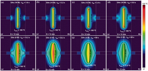
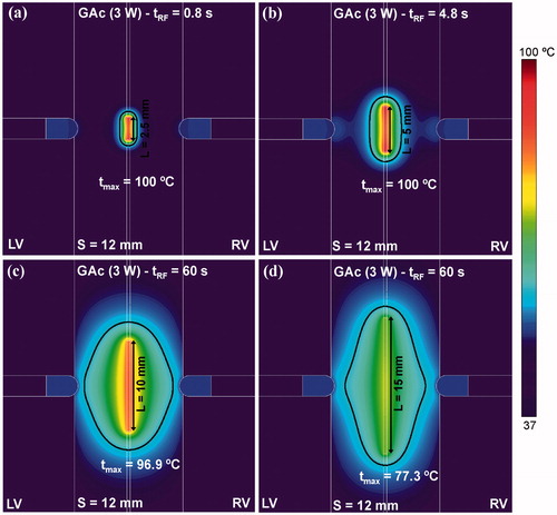
After confirming that a 4 W power level was suitable for energising the guidewire, we analysed the effect of increasing the length of the energised guidewire zone (L) from 2.5 to 15 mm using the same power level on the temperature distributions and thermal lesion shapes (see ). As shown in , short lengths (L ≤ 5 mm) were associated with early overheating and thermal lesions confined to around the wire. Length of 10 mm is probably the best to avoid very early overheating and achieve an appreciable lesion volume around the guidewire.
Figure 7. Effect of the length of the energised zone in the guidewire (ranging from 2.5 to 15 mm) on the temperature distribution in the tissue. Computer simulations were stopped when maximal temperature in the tissue reached 100 °C (tRF). Power of 4 W was applied between the energised zone and the irrigated-tip electrodes.
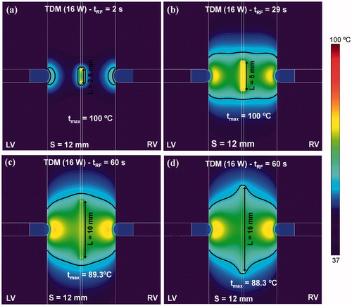
The results obtained so far suggest that while bipolar RF ablation is best at creating especially wide lesions in both endocardial zones (see and ), the RF-energised guidewire is better at creating spatially located lesions in the middle of the septum (see and ). From this analysis, our proposal was to combine both ablation modes by means of a TDM technique. In order to make TDM feasible a constant power of 16 W was applied throughout the ablation, i.e. the same power level was used during the standard bipolar ablation and the RF-energised guidewire ablation. shows the effect of increasing the length of the guidewire energised zone (L) from 2.5 to 15 mm using TDM on temperature distributions and thermal lesion shapes. Although early overheating still occurred for short wire lengths, the results showed an optimal lesion filling almost all the septum zone beneath the irrigated-tip electrodes using the technique for larger guidewires. The best thermal lesion was achieved with a 10 mm guidewire without overheating the tissue (the maximum temperature reached in the tissue is 89.3 °C).
Figure 8. Temperature distributions and thermal lesion contour (black line) in a 12 mm thick ventricular septum created by time-division multiplexing (TDM) where bipolar RF ablation is conducted for 90% of the time and RF-energised guide wire is conducted 10% of the time (see text for more details). Distributions are those of different lengths of energised zone in the guidewire, from 2.5 to 15 mm. Computer simulations were stopped when maximal temperature in the tissue reached 100 °C (tRF).
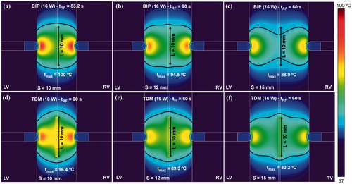
In order to check the possible advantage of TDM over the sole bipolar ablation, compares the temperature distributions and thermal lesion contours (black line) obtained for both modes when septal wall (S) thickness varies between 10 and 15 mm. The TDM technique allowed wider lesions to be created in the middle of the ventricular wall, avoiding the hour-glass shape associated with the bipolar technique, especially with very thick ventricular walls (15 mm, ).
Figure 9. Comparison between alone bipolar mode (a–c) and time-division multiplexing (TDM) technique (d–f) on temperature distributions and thermal lesion contours (black line) obtained for three thicknesses of ventricular septum (10, 12 and 15 mm). Computer simulations were stopped when maximal temperature in the tissue reached 100 °C (tRF). A constant power of 16 W was applied throughout the ablation.
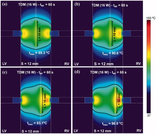
shows the effect of displacing the guidewire to one side of the septal wall on the temperature distributions and thermal lesions. We observed that although the guidewire was not located exactly in the middle of the septum, the thermal lesion was equally effective (i.e. transmural). However, an increment of up to 7 °C was observed in the maximum temperature reached in the tissue between the guidewire and nearest irrigated-tip electrode when the guidewire was displaced 3 mm away from the midplane ().
Figure 10. Effect of the displacement of the RF-energised guidewire (10 mm length) to one side on the temperature distributions and thermal lesion contours (black line). The lateral displacement considered from the midpoint of the septum was: (a) 0 mm (without displacement), (b) 1 mm, (c) 2 mm and (c) 3 mm. Computer simulations were stopped when maximal temperature in the tissue reached 100 °C (tRF).
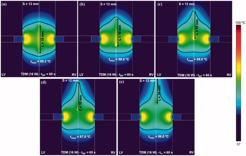
In contrast, as shown in , the effect of a vertical guidewire displacement along the midplane made the lesion extend along the guidewire itself, while the maximum temperature was slightly reduced (around 3 °C when the guidewire shifts up to 10 mm from the midpoint ().
Figure 11. Effect of the displacement of the RF-energised guide wire (10 mm length) along the midplane on the temperature distribution in the tissue and thermal lesion contours (black line). The longitudinal displacement considered from the midplane of the septum was: (a) 0 mm (without displacement), (b) 2.5 mm, (c) 5 mm, (c) 7.5 mm and (d) 10 mm. Computer simulations were stopped when maximal temperature in the tissue reached 100 °C (tRF).
Discussion
This computer modelling study explored whether a guidewire placed in a coronary vein in the middle of the septum could enhance the RF ablation of ventricular arrhythmias by applying RF power directly between itself and a couple of irrigated electrodes on each side of the septal wall. Since the aim was to improve the current bipolar mode conducted with these electrodes, the first simulations were intended to characterise this mode. The results were similar to those found in the case of bipolar ablation with two internally cooled electrodes [Citation19]: a power of 16 W was optimal to create transmural lesions through the ventricular wall and simultaneously avoid an hourglass-like shape (see ). In fact, bipolar ablation is used for resistant septal VTs and should take preference over the new method based on an RF-energised guidewire. However, bipolar septal ablations not only fail to control septal VTs (by rendering them non-inducible) in approximately 50% of patients, but are also related to a large number of clinical recurrences (similar to ethanol septal injection) [Citation20]. The main reason for bipolar ablation not working in septal VTs is supposed to be the thickness of the septal wall. In clinical practice, bipolar ablation works well when the two active catheters are less than 10 mm from each other. The difficult septal VTs are typically located deep inside the septal wall, where bipolar ablation cannot reach, so that an RF-energised guidewire could be a clinical option for treating this type of VT when alternative methods cannot work.
In this respect, the first idea was to take advantage of the metal in the guidewire to make it act passively as a secondary electrode immersed in the current density field created by the pair of irrigated electrodes. This phenomenon has previously been observed in small metal pieces placed near RF ablation electrodes [Citation21], and hence, could be exploited to enlarge the lesion around the guidewire. However, the computer results suggest that the role of the metal part of the guidewire as a secondary electrode is practically negligible (see ), and so it has to be made to actively deliver RF power.
If the metal part of the guidewire acts as a primary electrode, it seems obvious that due to its having a smaller area than the irrigated electrodes, these will act as dispersive electrodes. The results confirmed this theory, at least for relatively high powers (14–16 W, see ). However, under these conditions, early overheating occurs around the guidewire, which would cause steam pops, as observed experimentally in a previous ex vivo study in which a 0.5 mm guidewire was energised with 20 W for 20 s [Citation6]. Consequently, low power has to be programmed when a thin guidewire is RF-energised in order to avoid rapid overheating and hence to make the thermal lesion grows. Our results suggest a value of 3–4 W (see ), and a metal guidewire length of ∼10 mm (see . Interestingly, this power level is very similar to those employed in experimental RF cardiac ablation studies with needle electrodes (3–4 W for a 0.4 mm electrode [Citation22], and ∼2 W for a 0.5 mm electrode [Citation23]). In fact, once inserted into the tissue, a needle electrode will act as a guidewire from an electrical and thermal point of view. Summarizing thus far, while the bipolar mode with 16 W allows especially wide thermal lesions in both endocardial zones (see ), a guidewire energised with 3–4 W seems to be suitable for creating lesions spatially located in the middle of the septum (see ). In order to create a thermal lesion sufficiently wide through the entire ventricular wall, the TDM technique is expected to combine the advantages of each mode. Although the advantage of TDM over the bipolar mode is not evident for a 12 mm ventricular wall ( vs. Citation5(e)), it does become relevant when a thicker wall is considered. For instance, for a thickness of 15 mm, while bipolar failed to create a wide lesion on the median plane (see ), TDM was able to create an equally broad lesion through the entire ventricular wall (see ). The results also suggest that this advantage would remain when the guidewire is displaced both from the median plane of the wall (see ) and with respect to the axis of the two electrodes (see .
As a limitation, the models did not solve the fluid dynamics problem, but they did use thermal convective coefficients at the electrode-blood and tissue-blood interfaces to simulate the thermal effect caused by circulating blood. Although this approximation is not enough to obtain a realistic blood temperature distribution, it can accurately estimate lesion depth in the tissue and also the maximum temperature reached in the tissue [Citation17]. Since, we were not interested in the blood temperature distributions (necessary, for example for studying factors involved in thrombus and char formation on the electrode), we used thermal convective coefficients to reduce the mathematical framework of the problem (avoiding fluid dynamics calculations) and consequently the computational cost.
Clinical risks and technical limitations
This computer modelling study was conducted to assess whether an RF-energised intracoronary guidewire would enhance bipolar ablation of the interventricular septum, especially when using a TDM technique. Although the results are promising in terms of achieving transmural ventricular wall lesions of up to 15 mm thick, the use of an RF-energised guidewire could involve clinical risks.
The creation of a thermal lesion within a vessel will certainly make the vessel wall partially collapse due to RF-induced heating. This phenomenon has been observed in other procedures based on endovascular RF ablation, such as endovenous ablation varicose vein treatment [Citation24] and RF-based renal denervation [Citation25]. As in these procedures, the main concern is avoiding stenosis, which mostly occurs in small vessels [Citation25]. Stenosis could reduce or even completely stop the blood supply in a specific zone of the ventricular wall. Future pre-clinical studies should, therefore, be planned to assess the safety of the RF-energised intracoronary guidewire in terms of stenosis and its clinical impact. As in the case of other procedures based on endovascular RF ablation, the degree of stenosis could be related to variables, such as the endovenous lesion length and applied power level [Citation25].
If the results of future pre-clinical studies reveal that complete stenosis occurs after using the RF-energised guidewire, pre-treatment angiographic mapping of the damaged zone would make it possible to assess if this risk is acceptable. In order to reduce the risks as far as possible, we consider that the RF-energised guidewire should be introduced into a venous rather than an arterial branch, as recently proposed for the ethanol injection [Citation26]. The technical limitations could be related to the metallic guidewire sticking to the inner wall of the vessel, which has been observed in endovenous varicose vein RF-ablation [Citation27]. Even though. there are potential clinical risks associated with the use of RF-energise intracoronary guidewire its clinical safety will only be confirmed after further pre-clinical and clinical studies, possibly focussed on the occurrence of RF-induced stenosis. In this respect, preliminary bench tests, such as the in-silico model presented here, play a crucial role in roadmapping the development of a new medical device. In other words, certain issues related to clinical safety (e.g. stenosis occurrence and its clinical impact) are clearly beyond of the scope of our computer model.
Additionally, from the procedural point of view, it has to be accepted that it will sometimes be difficult to position the two catheters and the guidewire, especially if only fluoroscopy is employed. However, electroanatomical mapping systems greatly facilitate this task and allow both catheters to be visualised and correctly positioned. The computer results suggest that once both catheters have been accurately placed, slight displacements of the guidewire do not impair the performance of the new technique (see and ).
In short, despite the risk of stenosis, we think that it could be acceptable to deliberately deliver RF energy into a septal branch to treat a VT under specific justified clinical situations. As in ethanol ablation, the RF-energised intracoronary guidewire could be considered exclusively as a bail-out technique for cases refractory to bipolar ablation [Citation28].
Conclusions
The use of an RF-energised guidewire combined with the TDM technique could enhance bipolar ablation aimed at eliminating a VT in the interventricular septum wall, especially in walls up to 15 mm thick. The safety of this new approach must be assessed in future pre-clinical studies, especially in terms of the risk of stenosis and its clinical impact.
Disclosure statement
The authors have no conflicts of interest or financial disclosures to make relevant to this submission.
Additional information
Funding
References
- Baszko A, Telec W, Kałmucki P, et al. (2016). Bipolar irrigated radiofrequency ablation of resistant ventricular tachycardia with a septal intramural origin: the initial experience and a description of the method. Clin Case Rep 4:957–61.
- Gizurarson S, Spears D, Sivagangabalan G, et al. (2014). Bipolar ablation for deep intra-myocardial circuits: human ex vivo development and in vivo experience. Europace 16:1684–8.
- Koruth JS, Dukkipati S, Miller MA, et al. (2012). Bipolar irrigated radiofrequency ablation: a therapeutic option for refractory intramural atrial and ventricular tachycardia circuits. Heart Rhythm 9:1932–41.
- Baldinger SH, Kumar S, Barbhaiya CR, et al. (2015). Epicardial radiofrequency ablation failure during ablation procedures for ventricular arrhythmias: reasons and implications for outcomes. Circ Arrhythm Electrophysiol 8:1422–32.
- Santangeli P, Shaw GC, Marchlinski FE. (2017). Radiofrequency wire facilitated interventricular septal access for catheter ablation of ventricular tachycardia in a patient with aortic and mitral mechanical valves. Circ Arrhythm Electrophysiol 10:e004771.
- Berjano EJ, Hornero F, Atienza F, Montero A. (2003). Long electrodes for radio frequency ablation: comparative study of surface versus intramural application. Med Eng Phys 25:869–77.
- McLellan AJ, Ellims AH, Prabhu S, et al. (2016). Diffuse ventricular fibrosis on cardiac magnetic resonance imaging associates with ventricular tachycardia in patients with hypertrophic cardiomyopathy. J Cardiovasc Electrophysiol 27:571–80.
- Berjano EJ. (2006). Theoretical modeling for radiofrequency ablation: state-of-the-art and challenges for the future. Biomed Eng Online 5:24.
- Pérez JJ, González-Suárez A, Berjano E. (2017). Numerical analysis of thermal impact of intramyocardial capillary blood flow during radiofrequency cardiac ablation. Int J Hyperthermia. doi: 10.1080/02656736.2017.1336258.
- Labonté S. (1994). Numerical model for radio-frequency ablation of the endocardium and its experimental validation. IEEE Trans Biomed Eng 41:108–15.
- Doss JD. (1982). Calculation of electric fields in conductive media. Med Phys 9:566–73.
- Pérez JJ, D'Avila A, Aryana A, Berjano E. (2015). Electrical and thermal effects of esophageal temperature probes on radiofrequency catheter ablation of atrial fibrillation: results from a computational modeling study. J Cardiovasc Electrophysiol 26:556–64.
- Byeongman J, Aksan A. (2010). Prediction of the extent of thermal damage in the cornea during conductive thermokeratoplasty. J Therm Biol 35:167–74.
- González-Suárez A, Berjano E. (2016). Comparative analysis of different methods of modeling the thermal effect of circulating blood flow during RF cardiac ablation. IEEE Trans Biomed Eng 63:250–9.
- Winterfield JR, Jensen J, Gilbert T, et al. (2016). Lesion size and safety comparison between the novel flex tip on the FlexAbility ablation catheter and the solid tips on the thermocool and ThermoCool SF ablation catheters. J Cardiovasc Electrophysiol 27:102–9.
- Pérez JJ, D'Avila A, Aryana A, et al. (2016). Can fat deposition after myocardial infarction alter the performance of RF catheter ablation of scar-related ventricular tachycardia?: results from a computer modeling study. J Cardiovasc Electrophysiol 27:947–52.
- González A, Pérez J, Berjano JE. (2017). Computer modeling of irrigated-tip electrodes during RF cardiac ablation: comparative analysis between including and excluding the problem of fluid dynamics. Proceeding of the Computing in Cardiology.
- Haines DE. (2011). Letter by Haines regarding article. Direct measurement of the lethal isotherm for radiofrequency ablation of myocardial tissue. Circ Arrhythm Electrophysiol 4:e67.
- González-Suárez A, Trujillo M, Koruth J, et al. (2014). Radiofrequency cardiac ablation with catheters placed on opposing sides of the ventricular wall: computer modelling comparing bipolar and unipolar modes. Int J Hyperthermia 30:372–84.
- Gianni C, Mohanty S, Trivedi C, et al. (2017). Alternative approaches for ablation of resistant ventricular tachycardia. Card Electrophysiol Clin 9:93–8.
- Boll DT, Lewin JS, Duerk JL, Merkle EM. (2003). Do surgical clips interfere with radiofrequency thermal ablation? AJR Am J Roentgenol 180:1557–60.
- Woo EJ, Tungjitkusolmun S, Cao H, et al. (2000). A new catheter design using needle electrode for subendocardial RF ablation of ventricular muscles: finite element analysis and in vitro experiments. IEEE Trans Biomed Eng 47:23–31.
- Blouin LT, Marcus FI. (1989). The effect of electrode design on the efficiency of delivery of radiofrequency energy to cardiac tissue in vitro. Pacing Clin Electrophysiol 12:136–43.
- Tao W, Jian-ping G, Xu H, et al. (2013). The effects of endovenous radiofrequency ablation on coagulation and the vein wall in an experimental canine model. Vascular 21:215–9.
- Andrea BR, Atié J, Desh S, et al. (2016). Safety and feasibility of transcatheter renal sympathetic denervation using different types of catheter and various radiofrequency settings. Int J Cardiol Heart Vasc 11:35–42.
- Schurmann P, Peñalver J, Valderrábano M. (2015). Ethanol for the treatment of cardiac arrhythmias. Curr Opin Cardiol 30:333–43.
- Badham GE, Strong SM, Whiteley MS. (2015). An in vitro study to optimise treatment of varicose veins with radiofrequency-induced thermo therapy. Phlebology 30:17–23.
- Kreidieh B, Rodríguez-Mañero M, Schurmann P, et al. (2016). Retrograde coronary venous ethanol infusion for ablation of refractory ventricular tachycardia. Circ Arrhythm Electrophysiol 9. doi: 10.1161/CIRCEP.116.004352.