
 ?Mathematical formulae have been encoded as MathML and are displayed in this HTML version using MathJax in order to improve their display. Uncheck the box to turn MathJax off. This feature requires Javascript. Click on a formula to zoom.
Abstract
Background: Stress urinary incontinence (SUI) is prevalent in adult women, attributed to weakened endopelvic supporting tissues, and typically treated using drugs and invasive surgical procedures. The objective of this in silico study is to explore transurethral high-intensity ultrasound for delivery of precise thermal therapy to the endopelvic tissues adjacent to the mid-urethra, to induce thermal remodeling as a potential minimally invasive treatment alternative.
Methods: 3D acoustic (Rayleigh–Sommerfeld) and biothermal (Pennes bioheat) models of the ultrasound applicator and surrounding tissues were devised. Parametric studies over transducer configuration [frequency, radius-of-curvature (ROC)] and treatment settings (power, duration) were performed, and select cases on patient-specific models were used for further evaluation. Transient temperature and thermal dose distributions were calculated, and temperature and dose metrics reported.
Results: Configurations using a 5-MHz curvilinear transducer (3.5 × 10 mm, 28 mm ROC) with single 90 s sonication can create heated zones with 11 mm penetration (>50 °C) while sparing the inner 1.8 mm (<45 °C) radial depth of the urethral mucosa. Sequential and discrete applicator rotations can sweep out bilateral coagulation volumes (1.4 W power, 15° rotations, 600 s total time), produce large volumetric (1124 mm³ above 60 EM43 °C) and wide angular (∼50.5° per lateral sweep) coverage, with up to 15.6 mm thermal penetration and at least 1.6 mm radial urethral protection (<5 EM43 °C).
Conclusion: Transurethral applicators with curvilinear ultrasound transducers can deliver spatially selective temperature elevations to lateral mid-urethral targets as a possible means to tighten the endopelvic fascia and adjacent tissues.
Introduction
Stress urinary incontinence (SUI), which refers to involuntary urine leakage due to physical exertion, sneezing or coughing, is the most common type of urinary incontinence disorder, commonly affecting up to 30% of adult women [Citation1–3]. Risk factors for SUI include advancing age, childbirth, smoking, and obesity [Citation4,Citation5]. SUI is caused by the weakening of endopelvic fascia and supportive tissues around the urethra, which renders the urethra and sphincter unable to withstand normal pelvic pressure and causing uncontrolled urine leakage [Citation6]. Currently, there are a variety of treatment options including behavior training, pelvic floor training with electrical stimulations, surgical procedures, absorbent products, occlusive devices, pharmaceutical therapy and thermal therapy [Citation7,Citation8]. The ‘gold standard’ option, which results in 90% improvement rates, is the surgical insertion of a synthetic tape implant in the mid-urethral region, which serves as a hammock to help support the tissue, increasing urethral pressure and mitigating unintended urinary leakage [Citation9–11]. However, it is an invasive surgery and can result in significant anesthetic intervention and duration, unpredictable complications, and prolonged recovery time [Citation12,Citation13].
As an alternative treatment to surgery, minimally invasive thermal therapy devices can deliver energy into target tissue to generate heat and cause tissue stiffening and remodeling. Higher temperatures (>50 °C) and thermal doses (>240 EM43 °C) can be applied for direct tissue tightening due to thermally induced collagen shortening and shrinkage, or necrosis and subsequent remodeling [Citation14–16]; and lower temperatures (45–50 °C) and thermal doses (10–240 EM43 °C) can be applied for a subtler tissue modulation without lethal damage to induce stiffening, fibrosis, as well as neocollagenesis [Citation17–19]. Non-invasive laser ablation is one form of thermal therapy that has been utilized for many applications such as skin rejuvenation and resurfacing thorough protein denaturation and collagen contraction [Citation20–22]. Recent studies reported laser-induced tissue denaturation and shrinkage can be used to remodel endopelvic fascia for treating SUI by transurethral or transvaginal application, yet undesirable thermal insult may occur at vaginal wall and urethral mucosa, due to limited penetration and selectivity [Citation23–25]. Transurethral radiofrequency (RF) current-heating devices, which deliver energy to the proximal urethra or bladder neck region to as a means to remodel endopelvic fascia, has been reported to improve SUI symptoms within 40–70% of the patients [Citation26,Citation27]; however, the responses are not durable, most likely because RF energy was limited to only 1–2 mm penetration depth of direct heating due to strong radial losses of energy [Citation28]. Additional needle insertion through urethral wall might increase the penetration to enhance collagen remodeling; however, it is more invasive than the other minimally invasive therapies [Citation25,Citation29].
In consideration of developing a novel and more effective approach to treating SUI, a precision transurethral energy source that can target tissue regions adjacent to the mid-urethra is required. In defining the proper target zone based upon physiologic studies, the weakest tissue region leading to SUI is around the middle section of the urethra, ∼1.5–2 cm from the bladder neck, where abdominal pressure is the highest [Citation6]. The targeted treatment region includes endopelvic fascia, pubourethral ligaments, the levator ani and other adjacent connective tissues, ligaments lateral to the urethra [Citation30]. Thermal treatment that tightens this tissue may produce a biologic ‘hammock’ by remodeling collagen and connective tissue and increasing hydrostatic pressure. Catheter-based transurethral ultrasound applicators have been previously demonstrated to produce spatially precise thermal distributions that may be applicable for SUI thermal therapy, and are capable of deeper penetration and more spatially controlled heating as compared to RF and laser technologies. Different variants of transurethral ultrasound applicators have been successfully utilized to precisely treat prostate targets under image guidance [Citation31–33]. Applicators with tubular transducers can create a larger angular heating volumes without mechanical rotation, but with shallow penetration [Citation34]. Applicators containing curvilinear or planar transducers, on the other hand, can emit as narrow as 10° acoustic energy and heating patterns, and by rotating the applicator sequentially can sweep out a treatment region with selective heating and deep penetration up to ∼20 mm [Citation35,Citation36].
The objective of the study is to investigate the performance of transurethral high-intensity ultrasound applicators as a means to precisely target heating in the endopelvic fascia and surrounding tissues along the mid-urethral zone, with potential to generate tissue stiffening and remodeling. A theoretical analysis, incorporating three-dimensional acoustic and bio-thermal modelling methods, was performed. Parametric studies across transducer design parameters (lightly focused curvilinear and planar geometries), applicator rotation schemes, and treatment settings using a generalized tissue block model were developed to characterize and determine favorable applicator and treatment configurations. Patient-specific tissue models were generated to bracket a range of anticipated anatomical settings, and corresponding simulations were performed to evaluate the performance of select transurethral applicators and treatment strategies by determining temperature and thermal dose distributions on target tissues surrounding the mid-urethra region. The intent is to demonstrate treatment strategies and performance characteristics for delivering moderate thermal damage and insult (45–60 °C) to discrete regions extending ∼15 mm from the urethra, while preserving urethral mucosa-submucosa, vagina, and bone structures.
Materials and methods
Transurethral ultrasound applicator
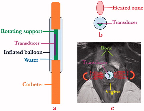
The schema for the proposed minimally invasive transurethral ultrasound applicator specific for SUI treatment is shown in , and is similar in concept to curvilinear devices designed for transurethral prostate ablation [Citation37]. The critical design features under consideration include a curvilinear ultrasound transducer (3.5 mm width, 10 mm length, concave across the width for light focusing, 5–7 MHz) assembly integrated within an inflatable urethral cooling/coupling balloon (7 mm OD, 20 mm length, inflated once deployed) filled with circulating temperature controlled water, positioned at the distal end of a flexible delivery catheter (4 mm OD). In concept, the transducer assembly can rotate within the catheter shaft and urethral cooling balloon for angular control of energy directivity. The transducer portion would be positioned within the urethra ∼15 mm from the bladder, adjacent to the area of weakest connective tissue, and can be manipulated for single or sequential sonications to form single narrow thermal treatment zones or to sweep out larger zones, respectively, to either side of the urethra while avoiding non-target regions such as the vagina (). Cooling water circulation can preserve the urethra surface, and the combination of applied power and sonication duration along with sequential rotation can define the angular and radial extent of thermal exposure.
Figure 1. Schema showing (a) coronal and (b) axial diagrams of transurethral ultrasound applicator and placement (c) for delivery of precision thermal therapy to lateral zones off the female mid-urethra for the treatment of SUI. (c) The position of urethral transducer, sequential rotation directions, and sonications with the order from 1 to 3 on one side and 4 to 6 on the opposite side represent a proposed heating strategy, with heated zones shown in red contours.
Theory
Heat transfer in tissue resulting from ultrasound energy can be described by the Pennes bioheat equation [Citation38]:
(1)
(1)
where, ρ is tissue density (kg m−3), C is the tissue specific heat (J kg−1 K−1), T is temperature (K or °C), t is time (s), k is tissue thermal conductivity (W m−1 K−1), Qm is the heat generated by metabolism (W m−3), and Q is the ultrasound power deposition (W m−3). Qm is considered negligible compared to acoustic power deposition in this work, and is neglected for simplicity during simulation [Citation39]. The term ωCb(T-Tb) refers to heat dissipated due to perfusion, where, ω, Cb and Tb denote blood perfusion rate (kg m−3 s−1), blood specific heat (J kg−1 K−1) and blood temperature (310.15 K, or 37 °C), respectively. The acoustic power deposition Q is defined as follows:
(2)
(2)
where, αa is the acoustic amplitude absorption coefficient (Np m−1) and c is the acoustic speed of sound (m s−1). In this work, we assume the amplitude attenuation coefficient and the absorption coefficient are equal, and that all scattered energy is absorbed locally. The acoustic pressure field p was calculated using the rectangular radiator method for numerical solution of the Rayleigh–Sommerfeld integral [Citation40]:
(3)
(3)
where, λ is the wavelength (m), α is the acoustic amplitude attenuation coefficient (Np m−1), Δw and Δh are the width (m) and height (m) of the small rectangular sub-elements on the transducer surface, R is the distance of the point from the rectangular element (m), N is the total number of rectangular elements, k is the wave number (m−1), and xn′ and yn′ are the Cartesian distances between the field point and sub-element center with respect to the local orientation of the sub-element coordinates in each rectangular sub-element on the transducer surface (m). un denotes complex surface velocity (m s−1) of the element n and it is approximated as follows:
(4)
(4)
where, I (W m−2) is the temporal average acoustic intensity at the transducer surface, defined by the applied acoustic power divided by the surface area of the transducer.
Thermal dose accumulation in terms of equivalent minutes at 43 °C (EM43 °C) is calculated for each field point using the transient temperature information based upon the definition of thermal dose as given below [Citation41]:
(5)
(5)
The iso-effect thermal dose contours were acquired to define regions of thermal exposure within the tissue. Based upon the temperature and dose ranges required for thermal damage and thermally induced remodeling, a value of 240 EM43 °C or greater is used to define direct coagulation and necrosis, while thermal doses of 40 EM43 °C–80 EM43 °C are used to define the lower threshold for subtle or less lethal acute thermal damage and insult, depending on the tissue types [Citation42,Citation43]. In this study, values of 10 EM43 °C, 60 EM43 °C and 240 EM43 °C were used to define the outer boundary of mild exposure region, moderate thermal damage region, and thermal coagulation region, respectively [Citation32,Citation44].
Biothermal simulation
To investigate applicator design, and evaluate the temperature and thermal dose distributions attainable within the target endopelvic fascia and surrounding tissue with high-intensity ultrasound energy, both a 3D generic tissue model with homogenous acoustic and thermal properties and patient-specific models with complex tissue structures surrounding the urethra were developed for acoustic biothermal simulations () [Citation45,Citation46]. Blood perfusion was modeled as a dynamic process, with a constant value () that was reduced to zero once the tissue region was coagulated at a dose threshold of 300 EM43 °C [Citation47]. The biothermal simulations of 3D generic and patient-specific models were based upon EquationEquation (1)(1)
(1) and performed using the finite element method in COMSOL Multiphysics 5.2 (COMSOL Inc., Burlington, MA). Meshing sizes within the models were variable, with smaller element sizes near the applicator and increasing toward the boundary of the model to achieve a better local solution and an efficient general computation. Based on convergence studies, the maximum element sizes were set as 0.6, 1.2 and 2.4 mm at the cylindrical regions within 5, 20, and 40 mm radially from the applicator respectively, with 25% gradual increment at the region boundaries. Acoustic deposited energy distributions were calculated from EquationEquations (2–4) using a MATLAB 2016a (MathWorks, Natick, MA) implementation of the rectangular radiator method [Citation48], and were imported into COMSOL Multiphysics prior to numerical simulation. Dirichlet conditions were applied to constrain the outer boundaries of the models as 37 °C. Water cooling within the ultrasound applicator balloon was simulated using convective heat transfer applied on the catheter wall:
(6)
(6)
where, n is the outward normal vector, the convective heat transfer coefficient h = 1000 W m−1 K−1 and cooling water temperature T∞ is set as 22 °C [Citation35]. An implicit time dependent solver with variable time steps (0.1 s<Δt <5 s) was utilized to solve the biothermal equation of the generic and patient-specific models, and temporal 3D temperature and thermal dose profiles were determined through FEM solution. The temperature and thermal dose solvers were convergent for the mesh resolution and time step settings used in the simulations.
Table 1. Thermal and acoustic physical properties of the 3D generic model and patient-specific models [Citation45,Citation46].
Parametric studies
Parametric studies of the transurethral ultrasound applicator were performed using the 3D homogenous generic tissue model to explore the relationship between sonication frequency, transducer radius of curvature, sequential rotation angle, sonication time, and applied power on resultant temperature and thermal dose profiles. The generic model consists of homogenous acoustic and thermal parameters () to represent generalized soft tissue of the urethra and surrounding structures, with 40 × 30 × 20 mm dimensions [Citation45,Citation46]. An ultrasound applicator with a curvilinear or planar transducer element (W = 3.5 mm, L = 10 mm) was modeled as centered within a water-filled thin-walled balloon (OD = 7 mm, L = 20 mm), as illustrated in . Acoustic powers of 1.4–1.75 W, frequencies of 5–7 MHz, sonication durations of 60–90 s, and transducer radius of curvature (ROC) ranged from 12 to 50 mm for the curvilinear configuration, and an ROC of ∞ to represent a planar transducer, were applied in acoustic biothermal simulations of single applicator position and sonication. The resultant temperature profiles were analyzed to determine the performance of the transducer in terms of urethral sparing and penetration depth. The urethral sparing, in radial depth from the balloon boundary, was defined by the 45 °C contour, following safety thresholds in transurethral microwave heating devices [Citation49]. The depth of penetration was defined by radial extents of the 50 °C contour, above which significant tissue stiffening is expected [Citation44]. These findings were used to determine the applicator configurations for single sonication to achieve deepest penetration of temperature distributions over 50 °C for engendering tissue remodeling, and at least 1.5 mm sparing from balloon for protection of urethral mucosa–submucosa, which has an approximate thickness of 1.2–1.4 mm [Citation50,Citation51].
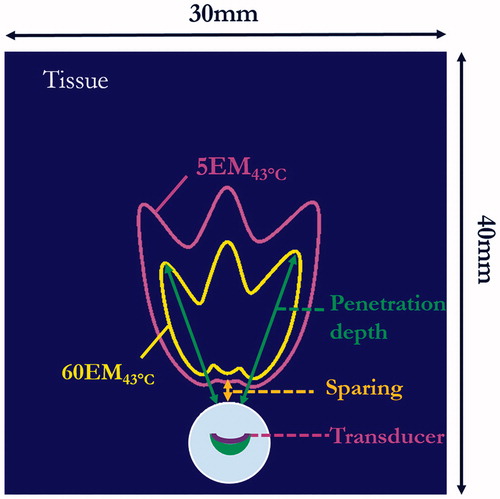
Simulations of multiple sonications by sequential discrete applicator rotations were performed using the applicator configuration described above, with rotation steps of 15–30° between individual sonications. Simulations for each rotational scheme were performed using a fixed number of distinct shots (n = 3) and the same sonication duration profile of 120 s–90 s–90 s, with the longer first shot sonication applied to accommodate the baseline starting temperature and generate more symmetrical final temperature and thermal dose contours. Maximum temperature and thermal dose distributions were determined, with temperature contours of 45 and 50 °C and thermal dose contours ranging from 5 to 240 EM43 °C for performance evaluation. The 5 EM43 °C contour was used to determine extents of sparing from urethra, penetration depths were described as radial extents of thermal dose contours of 10, 60 and 240 EM43 °C (.
Figure 2. Cross-sectional slice of 3D generic model and data metrics for parametric study based upon final thermal dose accumulation after sonications: the urethral sparing was defined based on thermal dose contour of 5 EM43 °C (magenta contours) and therapy penetration depth was defined based on the contours of 10 EM43 °C, 60 EM43 °C (shown in yellow contours) or 240 EM43 °C.
Patient-specific studies
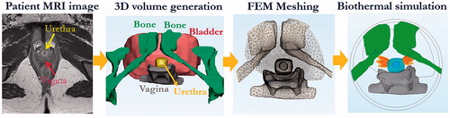
To evaluate the feasibility and performance of the transurethral ultrasound applicators for SUI treatment in a more realistic and complex setting, two 3D anatomical models were derived from patient imaging studies to represent example clinical cases. Model I represents a case with pelvic bone and a typical H-shape vaginal wall distinctly outside the target region, and Model II represents a narrow pelvis with pelvic bone and flattened vaginal wall in close proximity [Citation52]. The 3D finite element models incorporate the anatomical structures of the urethral mucosa and musculature, surrounding connective tissues, vagina wall, bladder, and pubic bone, as generated directly from segmentation of patient-specific 3D T2-weighted MRI images (. The MRI image segmentation and corresponding patient-specific finite element mesh generation were performed with Mimics Innovation Suite (Materialise, Leuven, Belgium), using Mimics and 3-Matic modules. FEM meshes were then exported into MATLAB and COMSOL Multiphysics for acoustic and biothermal simulations. The thermal and acoustic properties for each of the tissues are given in [Citation45,Citation46]. The acoustic beam intensity patterns and power deposition were numerically calculated onto the patient-specific models through EquationEquations (2–4) in MATLAB, and the profiles were then imported to COMSOL prior to thermal simulation. Propagation of ultrasound energy through the soft tissue/bone interface was approximated using 65% transmission, as previously used for investigations of ultrasound incident on bone from transurethral devices [Citation53].
Figure 3. Patient-specific model generation and simulation workflow, shown in the sequential order of MRI image segmentation, 3D volume generation, FEM meshing, and numerical acoustic and biothermal simulation to calculate transient temperature elevations and thermal dose accumulation (dose volumes of 60 EM43 °C and 240 EM43 °C are shown in yellow and orange, respectively).
Using the applicator configurations selected from the parametric studies, treatment strategies were evaluated on the two patient-specific models using the curvilinear transurethral applicator with sweeping sequential rotations in two separate right and left lateral directions. Power and orientation (rotation angles) of the applicators were adjusted to avoid thermal damage to the vagina, bone and bladder. Given that bone has greater absorption of ultrasound energy than soft tissue [Citation53], applied power was reduced to 50% of the original value as a means to reduce bone heating when acoustic beam patterns were directly incident on bone structures within 3 cm from the applicator. The transient temperature and thermal dose distributions for each case were computed by FEM biothermal simulation, and quantitative analysis of urethral sparing, maximum temperature in organs, thermally treated volumes and penetration depths was performed.
Results
Parametric studies
Different transurethral ultrasound device configurations for SUI treatment delivery were simulated using the 3D generic soft-tissue model. Examples of 2D temperature distributions in the central-axial transducer plane, at the end of a single-shot 90-s sonication with applied powers of 1.4–1.75 W, are shown for a curvilinear transducer with a fixed ROC = 20 mm and frequency of 5, 6, and 7 MHz, respectively (). Similarly, the temperature distributions for curvilinear transducers of different ROCs and a planar transducer, operating at 5 MHz are shown in . Urethral sparing depth, peak temperature, and penetration depth are summarized in for these cases. At a fixed ROC, as the frequency is increased the urethral sparing distance decreases and peak temperature increases (). Further, while keeping frequency constant and with increasing of radius of curvature, the urethral sparing distance increases and the peak temperature decreases (). The greatest penetration occurred at curvature radius ∼20–28 mm (). The applicator configurations with transducer frequency of 5 MHz and ROC of 20–28 mm, 1.4–1.575 W acoustic power and 90 s sonication could treat target tissue to a maximum temperature of 52–56 °C and penetration depths of 11–14 mm, with urethral sparing ranging from 1.5 to 1.8 mm.
Figure 4. Parametric studies of transducer frequency and radius of curvature (ROC): 90 s sonication with 3.5 × 10 mm curvilinear transducers (acoustic power = 1.4 W): (a–c) temperature distributions at frequencies of 5, 6 and 7 MHz, respectively, with ROC = 20 mm, indicating larger heated zones generated as frequency increased for constant power; (d–f) temperature distributions with different curvilinear ROCs of 12 mm, 28 mm, and ∞ (planar applicator), respectively, operating at 5 MHz. Temperature contours of 45 and 50 °C are shown to demonstrate the sparing distance from the balloon and the penetration depth, respectively.
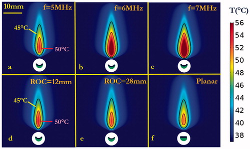
Figure 5 Summary of parametric studies on frequency and radius of curvature (ROC): (a–c) the sparing, peak temperature and penetration depth, respectively, of varying powers and frequencies (5–7 MHz) when ROC is fixed as 20 mm; (d–f) the sparing, peak temperature and penetration depth resulting from varying powers and ROC [12 mm to ∞ (planar)] when frequency is fixed at 5 MHz.
![Figure 5 Summary of parametric studies on frequency and radius of curvature (ROC): (a–c) the sparing, peak temperature and penetration depth, respectively, of varying powers and frequencies (5–7 MHz) when ROC is fixed as 20 mm; (d–f) the sparing, peak temperature and penetration depth resulting from varying powers and ROC [12 mm to ∞ (planar)] when frequency is fixed at 5 MHz.](/cms/asset/30005fc3-4b61-4bde-b1fc-fb05276e883c/ihyt_a_1456679_f0005_c.jpg)
Based upon the results above for single-shot applications, a select applicator configuration (acoustic power of 1.4 W, frequency of 5 MHz, and ROC of 28 mm) was used in simulation of three discrete sonication patterns at different separation angles, with the intent to produce larger sector zones of thermal exposure. The maximum temperature and thermal dose distributions were calculated for cases with sequential rotation angles between shots of 30°, 20° or 15°, as shown in and tabulated in . Maps of both maximum temperature and thermal dose show the applicator with sequential 30° rotation generated three discrete heating patterns with little overlap, while the application of sequential 15° or 20° rotation created a more concentrated and contiguous heated zone. As reported in , the simulation with sequential 15° rotation provided greatest penetration depth of 15.5 mm (>60 EM43 °C), greatest dose volume of 593.0 mm3 (>60 EM43 °C) and peak temperature of 56.6 °C, with moderate protection of urethra mucosa–submucosa with ∼1.5 mm urethral sparing. In contrast, the simulation with sequential 30° rotation had slightly better sparing of ∼1.8 mm yet with a lower penetration depth of 13.4 mm.
Figure 6. Thermal simulation of maximum temperature and thermal dose of generic tissue using the curvilinear ultrasound applicator for sequential three-shot sonication patterns. (a–c) Maximum temperature with 30°, 20° and 15° sequential rotations are shown respectively, with 45 °C (magenta) and 50 °C (black) contours. (d–e) Corresponding thermal dose with 30°, 20° and 15° sequential rotations are shown, respectively, with contours of 10 EM43 °C (magenta), 60 EM43 °C (white) and 240 EM43 °C (red). (The display of thermal dose was set at a maximum threshold of 240 EM43 °C for visualization purposes).
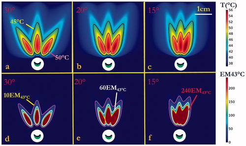
Table 2. Summary of thermal performance for sequential sweeping three shot simulations in the parametric-generic model using curvilinear transducer with 5 MHz, ROC of 28 mm, and 1.4 W applied power.
Patient-specific studies
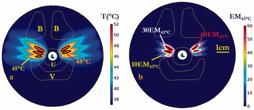
Numerical simulations in the two patient-specific models (Model I and Model II) were performed, using a 5 MHz, 28 mm ROC applicator configuration and sequential sonication settings (0.7–1.4 W applied power, 15° rotation angles, bilateral application of three shots each side with 120 s–90 s–90 s timing) derived from the parametric studies, as summarized in . Transient maximum temperature and thermal dose maps across the central axial plane in the mid-urethral region are shown for Model I in and , respectively, illustrating the sequential targeting and spread of therapeutic temperature (>50 °C) and thermal dose (>60 EM43 °C) distributions extending over 15 mm in depth from the inflated balloon, with ∼50° dual coverage angles, into the connective tissue surrounding the mid-urethra. The corresponding temperature and thermal dose contours in the coronal plane along the applicator length are illustrated in , with a slightly larger heated volume noted in the initial treatment side versus the second treatment side due to cumulative effects of a longer urethral cooling time for the latter portion. While the pubic bone structure in Model I was located predominately anterior to the urethra target zone or more than 4 cm distant, the pubic bone in Model II was more closely adjacent and was aligned with the target zone around the urethra, and thus would impact the heating. In order to compensate for the sixth shot in Model II, where the applicator was directed at pelvic bone within 3 cm depth, a 50% reduction in applied power (0.7 W) was empirically determined to prevent significant bone heating and thermal dose exposure (T < 50 °C, dose <60 EM43 °C). The final cumulative maximum temperature and thermal dose distributions are shown in , demonstrating moderately reduced penetration in the sector toward the bone, and maximum temperatures of 48.9 °C and thermal doses of 39.3 EM43 °C accrued in the bone. The simulation results on both patient-specific models demonstrate the curvilinear transducer with sequential rotation could heat the target surrounding tissue up to 56.5 °C with maximum penetration depth of 15.6 mm from the balloon, while providing 1.6 mm minimum urethral sparing (). Treatment volumes extending from mid-urethra of 899–1123 mm³ defined by dose over 60 EM43 °C could be produced with cumulative maximum coverage angles up to ∼50.5°. The 3D thermal dose isosurfaces () on both patient-specific models also demonstrate the directionality and selective targeting possible, and that the proposed strategy did not generate excessive heating or damaging thermal dose accumulation on the adjacent vagina or neighbouring bone, with no overlapping with the 60 EM43 °C isosurfaces.
Figure 7. Cumulative maximum temperature distributions of the central axial plane at the end of each sequential sonication at (a) 120, (b) 210, and (c) 300 s for rotations of 15°, and repeated on the opposite lateral side for a total procedure time of (d) 600 s. Temperature contours of 45 and 50 °C are shown, penetrating antero-laterally into surrounding connective tissues. Critical anatomy including the pubic bones (B), vaginal wall (V), and outer boundary of urethral stromal and muscle (U) are highlighted.
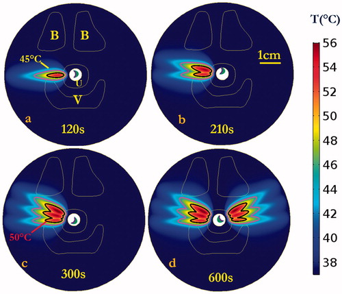
Figure 8. Cumulative thermal dose distributions, corresponding to the temperature elevations of , of the central axial plane at the end of each sequential sonication at (a) 120, (b) 210, and (c) 300 s for rotations of 15°, and repeat on the opposite side for total procedure time of (d) 600 s. Thermal dose contours of 10 EM43 °C, 60 EM43 °C and 240 EM43 °C are shown penetrating into the surrounding connective tissue. Critical anatomy including the pubic bones (B), vaginal wall (V), and outer boundary of urethral stromal and muscle (U) are highlighted. (The display of thermal dose was set at a maximum threshold of 240 EM43 °C for visualization purposes).
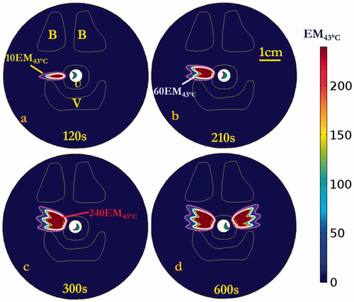
Figure 9. (a) Maximum temperature and (b) thermal dose distributions on the central coronal plane aligned with the axis of the applicator after 600 s sonication to target both sides of the mid-urethra. A slightly smaller heated zone was observed in the direction of the second side treated (right side in figure), due to the presence of urethral cooling for a longer time prior to sonication. Urethral muscular stroma (U) and bladder (Bl) are highlighted. (The display of thermal dose was set at a maximum threshold of 240 EM43 °C for visualization purposes).
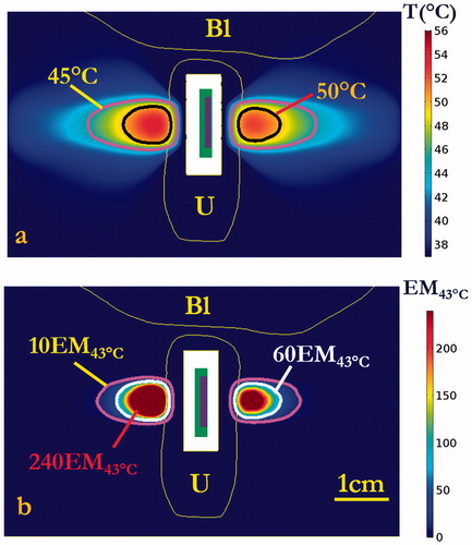
Figure 10. (a) Maximum temperature and (b) thermal dose of patient-specific Model II on the central axial plane after 600 s sonication. Temperature contours of 45 and 50 °C were shown in (a), and dose contours of 10 EM43 °C, 60 EM43 °C and 240 EM43 °C were shown in (b). Note due to patient positioning and anatomy, pelvic bone is delineated on one side only in this plane. (B denotes pubic bone, V denotes vagina, and U denotes urethral mucosa and surrounding layers of connective tissue. The display of thermal dose was set at a maximum threshold of 240 EM43°C for visualization purposes).
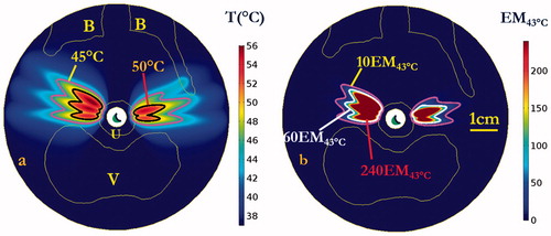
Table 3. Summary of patient-specific simulation settings and results, as applied using a transurethral curvilinear ultrasound device (5 MHz, ROC = 28 mm) with sequential rotation and sonication of left and right side lateral target regions along the mid-urethra on two anatomic models.
To investigate the thermal performance characteristics at lower maximum temperatures and thermal doses, and to represent a conservative treatment compared with those achieved at higher power levels, a final set of simulations was performed with 25% less applied power (1.05 W) on Model I. illustrates the lower power treatment strategy could produce therapeutic temperatures of 45–50 °C, extending 10.9 mm and a volume of 81.1 mm³ over 60 EM43 °C into the supporting tissue around the mid-urethra. While this strategy produced less penetration depth and smaller treatment volumes, it provides better protection of urethral mucosa–submucosa with a 2.6 mm sparing from balloon. Moreover, the strategy generated less heat on the bone and vagina, with reduced maximum temperatures of 44.5 and 43.2 °C, respectively, and lower maximum dose of 2.5 EM43 °C and 1.1 EM43 °C, respectively.
Figure 11. 3D Thermal dose distribution of patient-specific simulations for (a) Model I and (b) Model II. 60 EM43 °C and 240 EM43 °C isosurfaces are shown in yellow and orange respectively, indicating ultrasound energy and therapeutic temperature and dose levels were delivered selectively to the target region with deep penetration, without thermal damage on sensitive structures such as bone and vagina (note that thermal distributions are behind the bone in (a)). (B represents pubic bone, V denotes vagina, and U denotes urethral mucosa and surrounding layers of connective tissue).
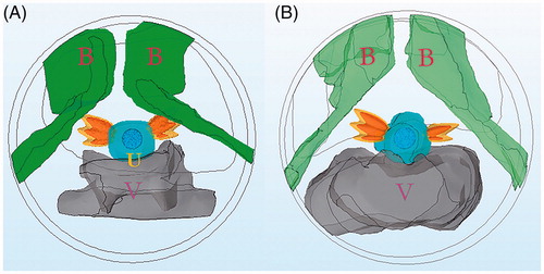
Figure 12. Maximum temperature (a) and thermal dose (b) of patient-specific Model I on the central axial plane after 600 s sonication with lower conservative applied power of 1.05 W. Temperature contours of 45 and 48 °C are shown in (a), and dose contours of 10 EM43 °C, 30 EM43 °C and 60 EM43 °C are shown in (b). (B denotes pubic bone, V denotes vagina, and U denotes urethral mucosa and surrounding layers of connective tissue. The display of thermal dose was set at a maximum threshold of 60 EM43 °C for visualization purposes).
Discussion
The aim of this study was to investigate the feasibility of using transurethral high-intensity curvilinear ultrasound devices to deliver localized heating to tissues adjacent to the female mid-urethra, with potential as a minimally invasive approach to induce local tissue remodeling toward the treatment of SUI. In silico studies using parametric-generic and patient-specific biothermal-acoustic models demonstrated the curvilinear ultrasound applicators can selectively deliver acoustic energy and well-defined and penetrating temperature elevations and thermal dose exposure in targeted supporting tissues adjacent to the mid-urethra, while effective urethral cooling affords protection of urethral mucosa–submucosa tissues. Further, through implementation of sequential rotation of the ultrasound transducer assembly during therapy, the transurethral devices can precisely deliver therapeutic temperature elevations to larger tissue volumes while discretely avoiding thermal damage to the neighboring vaginal wall and pelvic bone.
The therapeutic mechanism proposed in this study is to precisely apply ultrasound based heating into targeted endopelvic tissues surrounding the urethra, as a means of inducing direct thermal collagen modification and shrinkage, or tissue remodeling. Some examples of heat-directed tissue modification and tightening are seen clinically using RF and laser energy sources in vaginal and anal laxity treatment [Citation54–56], skin rejuvenation [Citation57–60] and SUI treatment from within the urethra, vagina, or surgical needle implants [Citation1,Citation25,Citation29]. Herein, the selective delivery of ultrasound-based heating is predicted to cause tissue contraction and thermal lesions that resorb and remodel over time, resulting in tightening or strengthening of the endopelvic tissues in the typically weakest area located along the mid-urethra, and thus hopefully provide improvement of SUI-related symptoms. The small lesions of higher temperatures (>50 °C) can create direct thermal induced collagen denaturing and subsequent collagen deposition through the processes of wound healing, remodeling, scar formation, and contraction [Citation28,Citation61–64], while surrounding lower temperature (45–50 °C) exposure can reinvigorate or rejuvenate tissue regions with collagen deposition [Citation17,Citation65,Citation66]. Through these tissue-modulating effects, it may be possible to enhance urethral support and mimic the hammock effect produced by the more invasive surgical sling implantation.
Transurethral ultrasound applicators with curvilinear transducers capable of rotation can precisely and selectively treat target tissues from within the urethra to therapeutic temperatures capable of generating tissue remodeling. Depending upon the desired temperature elevation, thermal dose exposure, and penetration distance, the applied power and duration of exposure can be adjusted accordingly. The ultrasound energy and resultant temperature and thermal dose profiles from single-shot sonications are very well-defined by the dimensions and geometry of the ultrasound transducer, ensuring that the energy deposition can be targeted and constrained within the desired target region. Based upon parametric studies (), devices with an ROC = 28 mm and operating at 5 MHz at applied acoustic power levels of 1.4 W for 90 s were found to produce favorable penetration of over 50 °C temperature elevation to 11 mm depth, while limiting temperature and dose to >1.8 mm urethral tissue. Furthermore, applying sequential and discrete rotation of this ideal design (5 MHz, ROC = 28 mm) during selective sonication of tissues lateral to the urethra, larger heated volumes over 1100 mm3 above thermal dose of 60 EM43 °C with ∼15 mm maximum penetration depth from the urethra can be achieved within 10 min (), whereas angular expanse can be determined by the number of sequential rotations and angle of increment. Compared to laser and RF treatments, which offer limited penetration of 1–5 mm [Citation25,Citation67,Citation68], the transurethral ultrasound applicator is capable of generating larger and deeper heated volumes while maintaining a lower maximum temperature, which could enhance thermal remodeling of deeper supporting tissues lateral to the urethra.
This transurethral applicator configuration and strategies herein, with fine spatial control and sequential rotation, can be applied to distinctly target desired tissues while avoiding thermal damage to sensitive organs. The directional heating patterns generated by rotational curvilinear ultrasound applicators could be positioned to avoid thermal damage on the vagina and pubic bone. The directional heating patterns generated by rotational curvilinear ultrasound applicators could be positioned to avoid thermal damage on the vagina and pubic bone. The curvilinear ultrasound applicator with selected configurations were shown on both models to only heat the vagina with maximum temperature up to 45.5 °C and thermal dose up to 6.1 EM 43°C (), which represents a non-lethal thermal insult. Bone has a much higher acoustic absorption rate compared to soft tissues, and thus bone that is in close proximity to the target region and in the beam path can preferentially absorb ultrasound energy with higher temperatures achieved compared to adjacent soft tissue [Citation53]. By adjusting the applied powers, the proposed thermal treatment also can avoid or reduce heating of the pubic bone to tolerable levels, with a maximum thermal dose <40 EM43 °C and only 0.2% of the volume >5 EM43 °C. Further refinement or optimization of the applicator position or rotation scheme specific to the patient anatomy can achieve better sparing or preservation of these tissues. Additionally, due to 22 °C temperature water cooling of the urethral surface, the present study indicates at least 1.6 mm urethral sparing (2.6 mm for low power option) using our conservative 5 EM43 °C threshold. These results show better protection of urethral mucosa and submucosa than other energy-deliver modalities such as laser, which have been shown to offer only 0.6 mm urethral preservation [Citation23–26]. Although not covered in this study, by inference the urethral protection could also be enhanced by using lower temperature water cooling within the cooling balloon [Citation48,Citation69]. In consideration of the thermal treatment of SUI, the urethra is a multi-layer structure that consists of mucosa, submucosa, smooth muscle and striated muscle [Citation70,Citation71]. As the weakness and reduced thickness of outer layer of striated muscle is closely related with SUI [Citation72], the current ultrasound strategy could heat the outermost smooth muscle and striated muscle layers of the urethra with maximum temperature over 53 °C ( and ) to produce tissue remodeling and strengthening.
The numerical simulations performed in this study are intended to assist in the further development of transurethral ultrasound devices and related treatment strategies for SUI applications. Ranges of applied power (1.4–1.75 W) and frequency (5–7 MHz) were selected from a practical perspective; however, lower frequencies beyond this range may provide increased penetration and sparing, although excessive penetration, greater power requirements, and subsequent bone heating could occur [Citation53]. A strategy of three discrete and sequential sonications at each lateral side of urethra was adopted rather than a continuous sweeping strategy, due to its more practical implementation in a minimally invasive clinical setting, acceptable performance in protection of sensitive organs and treated volumes, and reasonable total treatment time of 10 min. In this work with constant acoustic power input, the heated volume on the first sweeping lateral side of the urethra was larger than the second side due to the accumulation cooling effects from the urethral cooling; however, slightly greater power levels or durations for each shot could be applied to accommodate this difference, or cessation of cooling and a wait time can be added prior to the second half of delivery. Additionally, in consideration of a more conservative thermal exposure that may be suitable for the initial power levels applied in the dose escalation portion of a clinical pilot study, we also explored using 25% lower power levels (1.05 W) and dose strategies on patient-specific models (), demonstrating lower maximum temperatures and slightly smaller volumes of thermal damage and insult, but more protection of the urethral mucosa. Ultimately at this point in development the exact target temperature, thermal dose, and volume required for effective treatment of SUI with this approach are not fully determined; however, as demonstrated above, delivery strategies can be varied to tailor the heating as desired.
While these simulations highlight the promise of high-intensity ultrasound for SUI thermal treatment, the proposed treatment strategy also has some potential barriers when considering translation to a practical clinical setting. As seen in the patient-specific models, the treatment zones were largely affected by the spatial proximity of the vagina and bone structures relative to the urethra. A larger retropubic space might allow placement of more ultrasound shots and hence enhance the treatment effect, whereas a smaller retropubic space and/or an ‘H shaped’ vagina morphology which surrounds the urethra could constrain treatment zone coverage and possibly increase the risk of thermal insult to non-target tissues. Cooling of the vaginal wall through a cooled obturator positioned in the anterior portion of the vagina could be considered for expanding the treatment volume and enhancing vaginal sparing, following approaches similar to endocavity cooling used for laser treatment of SUI [Citation25], as well as prostate and cervical thermal therapy [Citation53,Citation69,Citation73]. Further, this cooling obturator could be positioned or shaped in a way to retract vaginal wall away from the target zones. Additionally, image based feedback using ultrasound elasticity or time series imaging, or MRI can be considered for more precise treatment application and monitoring. MRI thermometry can be applied to monitor the volumetric temperature evolution in target and non-target tissues in real-time [Citation74,Citation75], and provide for the means of feedback control to compensate for tissue heterogeneities and dynamic changes to properties. Ultrasound imaging can also be applied to aid applicator positioning and targeting, as well as potential for temperature or ablation monitoring [Citation76].
The patient-specific modeling herein was applied for feasibility assessment, as well as developing and characterizing preliminary delivery strategies and device designs in a generalized setting. We assumed urethral mucosa, endopelvic fascia and surrounding muscles, tissue and ligaments in patient-specific models have homogenous absorption and attenuation coefficients, and we did not consider dynamic changes due to temperature exposure. However, studies of attenuation changes as a function of tissue heating indicate that temperatures greater than 55 °C are required for these changes, which range from ∼1 to 1.5-fold increase for higher temperatures (55–70 °C) and possible decrease for ∼50 °C exposures [Citation77–79]. Additionally, we selected a moderate perfusion rate of 2 kg/m³ s within the urethra, vagina and adjacent tissue, and assumed perfusion rates would reduce to zero in thermally damaged regions above a cut-off dose of 300 EM43 °C, an approximation as similarly applied in clinical HIFU systems with real-time dose monitoring and other thermal therapy modeling [Citation43,Citation47,Citation80]. In practice, the perfusion rate and coagulation threshold might vary in these different tissues. For constant applied power, the penetration depth, maximum temperature and total treated volume would be decreased at higher perfusion rates; and would be increased at lower perfusion rate. Since the discrete thermal treatment zones from each sonication are characterized by steep thermal dose gradients, variations in the coagulation thresholds and the perfusion cut-off thermal dose values between the 200–400 EM43 °C range will most likely have little effect on the penetration depth, maximum temperature and treated volume. Moreover, our patient-specific model did not include extremely challenging or abnormal anatomical structure associated with pelvic floor failure or distortion of the retropubic space [Citation81]. However, we demonstrated with these models that the ultrasound approach has potential to compensate for complex anatomy through target selectivity, control of depth, modification of power levels and positioning. In contrast, RF and other techniques for transurethral treatment of SUI have limited penetration and spatial selectivity, which could render these approaches less versatile. The modeling platform provides an initial framework for continued development of more accurate and sophisticated modeling, advanced device design, development of treatment delivery strategies, and possibly lead to treatment planning. Additional simulations for various prospective temperature and thermal dose ranges can be performed, along with validation experiments to examine their biologic effects evaluated in vivo.
Conclusion
In summary, we have applied theoretical simulations to demonstrate the feasibility and potential of minimally invasive transurethral ultrasound to heat pelvic tissue lateral to the mid-urethra while protecting urethral mucosa, vagina, and pubic bone. These transurethral curvilinear ultrasound applicators with sequential rotation and sonication can precisely deliver therapeutic temperature distributions to target tissues with ∼15 mm penetration and directionally selective heating volumes defined by rotational positioning and sequencing.
Acknowledgment
This work is a collaboration between the University of California, San Francisco and Acoustic MedSystems supported by a Small Business Industry Research grant from the National Institutes of Health.
Disclosure statement
E. Clif Burdette is affiliated with Acoustic MedSystems, which has a commercial interest in interstitial ultrasound technology. No potential conflict of interest was reported by other authors.
Additional information
Funding
References
- Dmochowski RR, Blaivas JM, Gormley EA, et al. Update of AUA guideline on the surgical management of female stress urinary incontinence. J Urol. 2010;183:1906–1914.
- Abrams P, Cardozo L, Fall M, et al. The standardisation of terminology of lower urinary tract function: report from the Standardisation Sub-committee of the International Continence Society. Am J Obstet Gynecol. 2002;187:116–126.
- Hampel C, Wienhold D, Benken N, et al. Definition of overactive bladder and epidemiology of urinary incontinence. Urology. 1997;50:4–14.
- Peyrat L, Haillot O, Bruyere F, et al. Prevalence and risk factors of urinary incontinence in young and middle‐aged women. BJU Int. 2002;89:61–66.
- Luber KM. The definition, prevalence, and risk factors for stress urinary incontinence. Rev Urol. 2004;6(Suppl. 3):S3.
- DeLancey JO. Structural support of the urethra as it relates to stress urinary incontinence: the hammock hypothesis. Am J Obst Gynecol. 1994;170:1713–1723.
- Rovner ES, Wein AJ. Treatment options for stress urinary incontinence. Rev Urol. 2004;6(Suppl. 3):S29.
- Davila GW. Nonsurgical outpatient therapies for the management of female stress urinary incontinence: long-term effectiveness and durability. Adv Urol. 2011;2011:176498.
- Chaikin DC, Rosenthal J, Blaivas JG. Pubovaginal fascial sling for all types of stress urinary incontinence: long-term analysis. J Urol. 1998;160:1312–1316.
- Niemczyk P, Klutke J, Carlin B, et al. United States experience with tension-free vaginal tape procedure for urinary stress incontinence: assessment of safety and tolerability. Tech Urol. 2001;7:261–265.
- Cox A, Herschorn S, Lee L. Surgical management of female SUI: is there a gold standard? Nat Rev Urol. 2013;10:78–89.
- Abouassaly R, Steinberg JR, Lemieux M, et al. Complications of tension‐free vaginal tape surgery: a multi‐institutional review. BJU Int. 2004;94:110–113.
- Deng DY, Rutman M, Raz S, et al. Presentation and management of major complications of midurethral slings: are complications under‐reported? Neurourol Urodyn. 2007;26:46–52.
- Farina L, Weiss N, Nissenbaum Y, et al. Characterisation of tissue shrinkage during microwave thermal ablation. Int J Hyperthermia. 2014;30:419–428.
- Liu D, Brace CL. CT imaging during microwave ablation: analysis of spatial and temporal tissue contraction. Med Phys. 2014;41:113303.
- Wall MS, Deng X-H, Torzilli PA, et al. Thermal modification of collagen. J Shoulder Elbow Surg. 1999;8:339–344.
- Hantash BM, Ubeid AA, Chang H, et al. Bipolar fractional radiofrequency treatment induces neoelastogenesis and neocollagenesis. Lasers Surg Med. 2009;41:1–9.
- Hecht P, Hayashi K, Cooley AJ, et al. The thermal effect of monopolar radiofrequency energy on the properties of joint capsule. An in vivo histologic study using a sheep model. Am J Sports Med. 1998;26:808–814.
- Medvecky MJ, Ong BC, Rokito AS, et al. Thermal capsular shrinkage: basic science and clinical applications. Arthroscopy. 2001;17:624–635.
- Papadavid E, Katsambas A. Lasers for facial rejuvenation: a review. Int J Dermatol. 2003;42:480–487.
- Ross EV, Yashar SS, Naseef GS, et al. A pilot study of in vivo immediate tissue contraction with CO2 skin laser resurfacing in a live farm pig. Dermatol Surg. 1999;25:851–856.
- Metelitsa AI, Alster TS. Fractionated laser skin resurfacing treatment complications: a review. Dermatol Surg. 2010;36:299–306.
- Pardo JI, Solà VR, Morales AA. Treatment of female stress urinary incontinence with Erbium-YAG laser in non-ablative mode. Eur J Obstet Gynecol Reprod Biol. 2016;204:1–4.
- Chang C-H, Myers EM, Kennelly MJ, et al. Optical clearing of vaginal tissues, ex vivo, for minimally invasive laser treatment of female stress urinary incontinence. J Biomed Opt. 2017;22:018002.
- Hardy LA, Chang CH, Myers EM, et al. Computer simulations of thermal tissue remodeling during transvaginal and transurethral laser treatment of female stress urinary incontinence. Lasers Surg Med. 2017;49:198–205.
- Appell RA, Juma S, Wells WG, et al. Transurethral radiofrequency energy collagen micro‐remodeling for the treatment of female stress urinary incontinence. Neurourol Urodyn. 2006;25:331–336.
- Elser DM, Mitchell GK, Miklos JR, et al. Nonsurgical transurethral collagen denaturation for stress urinary incontinence in women: 12-month results from a prospective long-term study. J Minim Invasive Gynecol. 2009;16:56–62.
- Edelstein PS. A preclinical study of nonsurgical radiofrequency collagen remodeling for the treatment of stress urinary incontinence. Exp Rev Med Dev. 2006;3:743–748.
- Lukban JC. Transurethral radiofrequency collagen denaturation for treatment of female stress urinary incontinence: a review of the literature and clinical recommendations. Obstet Gynecol Int. 2011;2012:384234.
- Fielding JR, Dumanli H, Schreyer AG, et al. MR-based three-dimensional modeling of the normal pelvic floor in women: quantification of muscle mass. Am J Roentgenol. 2000;174:657–660.
- Diederich C, Stafford R, Nau W, et al. Transurethral ultrasound applicators with directional heating patterns for prostate thermal therapy: in vivo evaluation using magnetic resonance thermometry. Med Phys. 2004;31:405–413.
- Burtnyk M, Chopra R, Bronskill M. Simulation study on the heating of the surrounding anatomy during transurethral ultrasound prostate therapy: A 3D theoretical analysis of patient safety. Med Phys. 2010;37:2862–2875.
- Chopra R, Colquhoun A, Burtnyk M, et al. MR imaging-controlled transurethral ultrasound therapy for conformal treatment of prostate tissue: Initial feasibility in humans. Radiology. 2012;265:303–313.
- Zini C, Hipp E, Thomas S, et al. guided focused ultrasound surgery for prostate cancer. World J Radiol. 2012;4:247.
- Ross AB, Diederich CJ, Nau WH, et al. Curvilinear transurethral ultrasound applicator for selective prostate thermal therapy. Med Phys. 2005;32:1555–1565.
- Chopra R, Baker N, Choy V, et al. MRI-compatible transurethral ultrasound system for the treatment of localized prostate cancer using rotational control. Med Phys. 2008;35:1346–1357.
- Ross AB, Diederich CJ, Nau WH, et al. Highly directional transurethral ultrasound applicators with rotational control for MRI-guided prostatic thermal therapy. Phys Med Biol. 2004;49:189.
- Pennes HH. Analysis of tissue and arterial blood temperatures in the resting human forearm. J Appl Physiol. 1948;1:93–122.
- Prakash P, Salgaonkar VA, Diederich CJ. Modelling of endoluminal and interstitial ultrasound hyperthermia and thermal ablation: applications for device design, feedback control and treatment planning. Int J Hyperthermia. 2013;29:296–307.
- Ocheltree KB, Frizzel L. Sound field calculation for rectangular sources. IEEE Trans Ultrason Ferroelectr Freq Control. 1989;36:242–248.
- Sapareto SA, Dewey WC. Thermal dose determination in cancer therapy. Int J Radiat Oncol Biol Phys. 1984;10:787–800.
- Yarmolenko PS, Moon EJ, Landon C, et al. Thresholds for thermal damage to normal tissues: an update. Int J Hyperthermia. 2011;27:320–343.
- McDannold N, Tempany CM, Fennessy FM, et al. Uterine leiomyomas: MR imaging-based thermometry and thermal dosimetry during focused ultrasound thermal ablation. Radiology. 2006;240:263–272.
- Dewhirst MW, Viglianti B, Lora-Michiels M, et al. Basic principles of thermal dosimetry and thermal thresholds for tissue damage from hyperthermia. Int J Hyperthermia. 2003;19:267–294.
- Duck FA. Physical properties of tissues: a comprehensive reference book. London: Academic Press; 2013.
- Mcintosh RL, Anderson V. A comprehensive tissue properties database provided for the thermal assessment of a human at rest. Biophys Rev Lett. 2010;5:129–151.
- Prakash P, Salgaonkar VA, Clif Burdette E, et al. Multiple applicator hepatic ablation with interstitial ultrasound devices: theoretical and experimental investigation. Med Phys. 2012;39:7338–7349.
- Adams MS, Scott SJ, Salgaonkar VA, et al. Thermal therapy of pancreatic tumours using endoluminal ultrasound: parametric and patient-specific modelling. Int J Hyperthermia. 2016;32:97–111.
- Devonec M, Berger N, Perrin P. Transurethral microwave heating of the prostate—or from hyperthermia to thermotherapy. J Endourol. 1991;5:129–135.
- Perucchini D, DeLancey JO, Ashton-Miller JA, et al. Age effects on urethral striated muscle II. Anatomic location of muscle loss. Am J Obstet Gynecol. 2002;186:356–360.
- Wieczorek A, Wozniak M, Stankiewicz A, et al. 3-D high-frequency endovaginal ultrasound of female urethral complex and assessment of inter-observer reliability. Eur J Radiol. 2012;81:e7–e12.
- Bitti GT, Argiolas GM, Ballicu N, et al. Pelvic floor failure: MR imaging evaluation of anatomic and functional abnormalities. Radiographics. 2014;34:429–448.
- Wootton JH, Ross AB, Diederich CJ. Prostate thermal therapy with high intensity transurethral ultrasound: the impact of pelvic bone heating on treatment delivery. Int J Hyperthermia. 2007;23:609–622.
- Singh A, Swift S, Khullar V, et al. Laser vaginal rejuvenation: not ready for prime time. Int Urogynecol J. 2015;26:163–164.
- Millheiser LS, Pauls RN, Herbst SJ, et al. Radiofrequency treatment of vaginal laxity after vaginal delivery: nonsurgical vaginal tightening. J Sex Med. 2010;7:3088–3095.
- Sekiguchi Y, Utsugisawa Y, Azekosi Y, et al. Laxity of the vaginal introitus after childbirth: nonsurgical outpatient procedure for vaginal tissue restoration and improved sexual satisfaction using low-energy radiofrequency thermal therapy. J Women's Health. 2013;22:775–781.
- Fabi SG. Noninvasive skin tightening: focus on new ultrasound techniques. Clin Cosmet Investig Dermatol. 2015;8:47.
- Alster TS, Lupton JR. Nonablative cutaneous remodeling using radiofrequency devices. Clin Dermatol. 2007;25:487–491.
- Beasley KL, Weiss RA. Radiofrequency in cosmetic dermatology. Dermatol Clin. 2014;32:79–90.
- White WM, Makin IRS, Barthe PG, et al. Selective creation of thermal injury zones in the superficial musculoaponeurotic system using intense ultrasound therapy. Arch Facial Plast Surg. 2007;9:22–29.
- Coad JE, editor. Thermal fixation: a central outcome of hyperthermic therapies. Proc. SPIE. 2005;5698:1–8.
- Verrico A, Moore JV. Expression of the collagen-related heat shock protein HSP47 in fibroblasts treated with hyperthermia or photodynamic therapy. Br J Cancer. 1997;76:719.
- Capon A, Mordon S. Can thermal lasers promote skin wound healing? Am J Clin Dermatol. 2003;4:1–12.
- Hayashi K, Markel MD. Thermal modification of joint capsuleand ligamentous tissues. Oper Tech Sports Med. 1998;6:120–125.
- Burdette EC, Lichtenstiger C, Rund L, et al. Ultrasound therapy applicators for controlled thermal modification of tissue. Proc of SPIE. 2011 [Feb 24]; [1–12]. DOI:10.1117/12.876639
- Dams S, Liefde‐van Beest D, Nuijs A, et al. Pulsed heat shocks enhance procollagen type I and procollagen type III expression in human dermal fibroblasts. Skin Res Technol. 2010;16:354–364.
- Dmochowski RR, Avon M, Ross J, et al. Transvaginal radio frequency treatment of the endopelvic fascia: a prospective evaluation for the treatment of genuine stress urinary incontinence. J Urol. 2003;169:1028–1032.
- Chang C-H, Wilson CR, Fried NM. Comparison of four lasers (λ = 650, 808, 980, and 1075 nm) for noninvasive creation of deep subsurface lesions in tissue. Proc SPIE. 2015;9542:95420G.
- Nau W, Diederich C, Ross A, et al., editors. Evaluation of endorectal and urethral cooling devices during MR-guided ultrasound thermal ablation in canine prostate. Conf Proc IEEE Eng Med Biol Soc. 2004;4:2492–2495.
- DeLancey JO. Why do women have stress urinary incontinence? Neurourol Urodyn. 2010;29(Suppl. 1):S13–S17.
- Strohbehn K, Quint LE, Prince MR, et al. Magnetic resonance imaging anatomy of the female urethra: a direct histologic comparison. Obstet Gynecol. 1996;88:750–756.
- Kim JK, Kim YJ, Choo MS, et al. The urethra and its supporting structures in women with stress urinary incontinence: MR imaging using an endovaginal coil. Ajr Am J Roentgenol. 2003;180:1037–1044.
- Hurwitz MD, Kaplan ID, Hansen JL, et al. Hyperthermia combined with radiation in treatment of locally advanced prostate cancer is associated with a favourable toxicity profile. Int J Hyperthermia. 2005;21:649–656.
- Kuroda K. MR techniques for guiding high-intensity focused ultrasound (HIFU) treatments. J Magn Reson Imaging. 2018;47:316–331.
- Grissom WA, Rieke V, Holbrook AB, et al. Hybrid referenceless and multibaseline subtraction MR thermometry for monitoring thermal therapies in moving organs. Med Phys. 2010;37:5014–5026.
- Ebbini ES, Ter Haar G. Ultrasound-guided therapeutic focused ultrasound: current status and future directions. Int J Hyperthermia. 2015;31:77–89.
- Tyréus PD, Diederich C. Two-dimensional acoustic attenuation mapping of high-temperature interstitial ultrasound lesions. Phys Med Biol. 2004;49:533.
- Damianou CA, Sanghvi NT, Fry FJ, et al. Dependence of ultrasonic attenuation and absorption in dog soft tissues on temperature and thermal dose. J Acoust Soc Am. 1997;102:628–634.
- Clarke R, Bush N, Ter Haar G. The changes in acoustic attenuation due to in vitro heating. Ultrasound Med Biol. 2003;29:127–135.
- Schlesinger D, Benedict S, Diederich C, et al. MR‐guided focused ultrasound surgery, present and future. Med Phys. 2013;40:080901.
- Brandão S, Parente M, Mascarenhas T, et al. Biomechanical study on the bladder neck and urethral positions: simulation of impairment of the pelvic ligaments. J Biomech. 2015;48:217–223.