
Abstract
Purpose: Bleeding from parenchyma transection during a robotic hepatic surgery remains the most critical point affecting postoperative recovery and long-term survival. Various robotic devices with different types of energies have been proposed; however, each of these lack in steerability, efficacy, or accuracy. The aim of this work is to evaluate the feasibility and performance of a new steerable microwave resection device intended for minimizing intraoperative blood loss during laparoscopic and robotic liver resections.
Methods: The new device operating at 2.45 GHz was designed to accommodate the engineering constraints derived from its use for robotic surgery or laparoscopy, in which a steerable head is required and the internal cooling of forced gas or water is undesirable. The device design, analysis, and optimization were addressed using the most advanced commercial electromagnetic and thermal solvers to achieve the best results. To experimentally validate the results of the numerical analysis, many ablations were performed on a freshly explanted bovine liver by using a single device prototype with three levels of energy supplied to the tissue. During the ablation procedures, the time, temperature, and shape of the thermal lesion were recorded using thermocouples and an infra-red thermos camera.
Summary: Ex vivo tests showed good agreement with the numerical simulations, demonstrating the validity of the simplifications adopted to deal with the complex phenomena involved in the extreme hyperthermia of a living tissue. The high performance, thermal reliability, and robustness of the developed device were also demonstrated along with the possibility of reducing operation time and blood loss.
Introduction
Thermal percutaneous ablation (TPA) for hepatic neoplasms has been recognized as a safe and effective method to treat patients with unresectable lesions at multiple and bilateral locations, inadequate hepatic reserve, multiple comorbidities, or contra-indications to general anesthesia or tumor down staging [Citation1–3]; moreover, it is conventionally performed for curative purpose to treat nodules up 30 mm in diameter [Citation4–6]. In addition, liver transplant and hepatic resection are still considered the gold standards in treating primary and secondary hepatic neoplasms because of their proven superior long-term disease-free survival rates compared with TPA [Citation6]. As the main problem during hepatic resection is bleeding from parenchyma transection, especially during laparoscopic and robotic intervention, the solution to this problem is considered of fundamental importance because it could solve problems related to the most postoperative recovery and long-term survival. Unfortunately, this aspect is currently limiting the spreading of minimally invasive surgical techniques; as a consequence, most of the interventions are still conducted using open techniques.
Moreover, several studies [Citation7–10] have underlined the importance of surgical resection, and a recent study has suggested that the indication for hepatic resection could be further extended by improving diagnostic methods and surgical skills and developing advanced technologies as robotic platforms. Consequently, various techniques and instruments have been developed to minimize bleeding during resection. Some of the most used devices are CUSA (Valleylab, Boulder, CO), harmonic scalpels, bipolar scissors, and hydro-dissectors but as described by Di Carlo et al. [Citation11] there are more than 20 different techniques for hepatic transection. The use of advanced and energy feeded instruments have improved the effectiveness of bleeding prevention during hepatectomy but the debate is still open and the surgeons have not identified yet an ideal instrument that joins speed, handling and coagulative effectiveness [Citation12–13].
Hepatectomy using coagulative necrosis (HCN) has been developed to avoid these bleeding-related problems. Curro et al. [Citation14] was the first to report on the use of a radiofrequency (RF) device (Habib 4X, RITA Medical System, Mountain View, CA, USA) to precoagulate the line of liver resection; subsequently, several studies confirmed the usefulness of this technique [Citation15–16].
Most HCN devices use RF technology because it is simple, relatively low cost and easy to use. Alternatively, in Japan, there have been several small-scale reports on clinical outcomes of hepatectomies using microwave tissue coagulation (MTC) which showed remarkable results in reducing intraoperative blood loss compared with more traditional methods and RF technology [Citation15–17].
Microwaves (MW), despite their complexity and costs, present several theoretical advantages compared to all the others type of hyperthermia energies [Citation18]. Unlike RF ablation, the energy penetration of MW ablation (MWA) is not affected by the electrical conductivity and permittivity of tissue. Moreover, the MWA has higher intratumoral temperatures, less severe heat sink effects, shorter ablation time, and larger ablation zone than RF.
The rapid progress in MW technology has recently attracted considerable attention in the development and optimisation of internally cooled [Citation18] and not internally cooled [Citation19] MW devices for the percutaneous MWA of liver tumors. Unfortunately, the development of new technologically advanced MW devices specifically intended for laparoscopic and robot-assisted MW coagulation procedures [Citation20] has received less attention. Liver resection using MTC has not yet become widespread because a simple, safe, and effective uncooled MW device useful for laparoscopic and robotic surgery is yet to be produced.
Objectives
The objectives of an ideal nonanatomical liver-resection procedure mainly involve the resection of the tumor by preserving a sufficient amount of free margin of healthy liver to guarantee oncological radicality and minimize intraoperative blood loss. In some cases, surgeons have tried to mutate the interventional radiology technique by using commercially available MW water- or gas-cooled needle applicators to produce sequential ablations along the ideal transection line to precoagulate the resection line in open surgery [Citation21–23] with good results in blood-loss minimization (coagulative puncta of approximately 10-mm diameter with a stitch length of ∼15–20 mm). However, for laparoscopic and robotic MW liver resection, this applicator type does not represent the optimal solution because its tip is not steerable and the forced cooling requires a complicated mechanical pumping subsystem and a pair of connection tubes for fluid circulation.
Therefore, the main objective of this study was to design a new uncooled steerable MW applicator by optimizing its mechanical structure by using the most advanced electromagnetic and thermos-kinetic numerical simulators.
Our goal was to create an optimized MW coagulator that should be capable of the following:
creating a small nonperfused zone associated with permanent clot firmness and excellent thermal stability;
preventing excessive tissue heating and consequent hepatic damage due to lateral MW spreading;
at the end of the procedure, the device temperature should not exceed 70 °C so as to prevent internal organ damage during laparoscopic and robotic procedures. To the best of the authors’ knowledge, this type of MW applicator has not been developed yet. Ultimately, the aim of this work is to numerically and experimentally evaluate the feasibility of a new liver-transection device optimized both for safe laparoscopic and robotic interventions, demonstrating that a well-designed and finalized device eases the procedure, reduces risks, and minimises the operative time for a safe hepatectomy.
Materials and methods
MW system setup
The proposed MW device has been conceived specifically to follow the previous objectives of mechanical simplicity, thermal stability, and safety. It is worth noting that by eliminating the internal cooling, the system complexity is drastically reduced in terms of refrigerant transport piping and pressure control systems; this improves manoeuvrability and eases the integration with laparoscopic and robotic tools. Consequently, the cost of the device, and therefore that of the entire procedure, can be reduced.
The ablation apparatus is composed of two main parts: a 2.45-GHz, 120-Watt MW generator designed by the Department of Information Engineering, University of Florence and a laptop to set the time and power parameters of the ablation sequences. The proposed device having dimensions compatible with laparoscopic and robotic interventions (i.e. length and diameter of 65 and 11.6 mm, respectively) is schematically shown in . It is composed of a 1-degree of freedom (DOF) steerable head supporting a short needle-shaped MW radiating antenna: the real prototype is shown in . The geometrical couplings and internal distribution of the components necessary for the functioning of the kinematics were designed to guarantee the maximum head steering angle of 120° (+60° up, −60° down), described as the optimum value by Adebar et al. [Citation24], without introducing connection discontinuities and propagation losses between the feeding coaxial cable and radiating element (antenna). The main dimensional constraints of the device are determined by its need to pass inside a standard laparoscopic trocar (12 mm), allowing maximum flexibility during all intervention phases and high manoeuvrability by a surgeon. To improve the capabilities of the device, a rotational DOF along the trocar’s axis was included, as suggested by Lum et al. [Citation25]. The rotation around the axis is allowed using two small radial ball bearings recessed on the internal stainless steel capsule (). The device is connected to the MW generator by using a flexible coaxial cable with 2.1 mm external diameter, the axial sliding of which is prevented by the fixing in the steel capsule.
Figure 1. (a) Schematic of the proposed device. (b) Internal mechanical structure. (c) Computational domain configuration in CST: (1) internal temperature of the needle; (2), (3) reference points for validation through thermo-camera measurements. (d) Computational domain configuration in solidworks flow simulation (SFS): (1) internal temperature of input needle obtained through CST results; (4) output reference point for validation through thermocouple measurements.
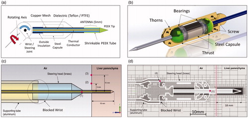
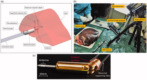
Figure 2. (a) Schematic description of the proposed procedure and its (b) laboratory setup, (c) real prototype in a bent state.
To eliminate the joint between the coaxial cable and radiating element, the needle is simply obtained as a straight extension of the coaxial feeding cable, drastically simplifying the whole structure and reducing possible causes of impedance mismatch. The end section of the needle, which must be inserted into the tissue, is coated with a thin layer of PEEK to increase its stiffness and robustness. PEEK is a biocompatible semicrystalline thermoplastic with excellent mechanical and chemical resistance properties that are retained at high temperatures. Electrical properties are relative permittivity 3.5, dissipation fact 1.5 × 10⁻³. PEEK has a glass transition temperature of ∼143 °C and melts at ∼343 °C. Its thermal resilience permits multiple sequential insertions into the liver parenchyma without structural damage. Furthermore, the high mechanical flexibility of the feeding coaxial cable allows a wide angle for the steering of the device head, permitting it to reach different parts of the liver through the same trocar entrance.
Experimental tests were conducted using the joint blocked because the steering was not necessary when operating on an explanted liver not enclosed in the abdominal wall ().
We performed the ablation procedure following a previously established resection line on the parenchyma capsule set at 10 mm along the pitch of the sequential ablations. The angle of insertion was maintained perpendicular to the organ capsule and aligned with the gravity vector. All the experimental tests were performed on an explanted bovine liver by setting the MW generator at its maximum output power of 120 W. In addition, we continuously monitored the procedure to capture thermal data by using a thermocouples analyser and a FLIR Thermal-CAM A320 (FLIR Systems, Inc., Wilsonville, OR), as shown in .
Numerical simulations
The numerical simulations were performed using two solvers. The first numerical simulation was conducted using the CST MICROWAVE STUDIO (https://www.cst.com) based on the finite element integration technique, which is a consistent discretization scheme for Maxwell’s equations in their integral form [Citation26]. The second part of the analysis was performed using Solidworks Flow Simulation (SFS) software (SolidWorks, Waltham, MA), which is a full 3D computation fluid dynamics (CFD) simulator capable of performing thermal analysis in fluids and solids considering conductive, convective, and irradiation exchange. This commercial solver on SFS is extremely flexible and works on the governing Navier–Stokes equation in its integral form with a discrete numerical technique based on the finite volume method [Citation27]. This method permits to analyse the flow behavior in internal cavities, such as vessels; in our specific case, the method considers the variation of the convection coefficient of the air surrounding the applicator. The air is treated as a free-flowing fluid, subject therefore to the effect of gravity. In fact, if heated, the fluid modifies its speed range by amplifying the convective exchange coefficient.
This choice was driven by the physical phenomena involved in the sequential ablation protocols: during the ablation pulse (Power ON) called the hot phase (HPh). The transient thermal analysis was performed using the CST Microwave Studio software, considering the simplifying hypothesis that electromagnetic (Maxwell) and thermal (Bio-Heat) equations are not coupled through the temperature dependence of the complex permittivity of the tissue. In the next phase (Power OFF), called cold phase (CPh), EM-radiated fields do not exist and the SFS permits concentration of computational resources based on the CFD analysis, considering with a higher flexibility in mesh refinement to more accurately analyse the geometrical complexity of the device. At the end of the HPh, we assumed a negligible delay time for extracting the needle from the ablated tissue and placing it in the next position. The transferred thermal field obtained from CST results defined the initial conditions for the CPh on SFS.
Near the MW antenna, the evolution of tissue temperature due to a high pulsed energy is very difficult to predict owing to vaporization, carbonization phenomena, and tissue deformation. To reduce the numerical burden on the CST simulator, we assumed an analysis domain constituted by a time- and space-invariant homogeneous isotropic liver tissue. The boundary condition of a perfectly matched layer was applied to the border of the domain. Based on our consultation with the surgical team, we set the drilling (insertion) depth of the radiating antenna in the liver tissue at 18 mm.
shows the CST model used for the HPh simulation in which the wrist joint was eliminated to reduce the mechanical complexity. This simplified model allowed us to estimate the time-dependent temperature evolution both in the tissue and device head. For the subsequent comparison with the results of the experimental tests, points 2 and 3 () were taken as reference.
The SFS analysis domain is depicted in . The geometrical heterogeneity was preserved and the mesh was refined according to the adaptive control of the solver that automatically identifies the most critical areas during computational calculation to reach the highest quality in terms of thermal distribution during the CPh.
The physical properties of the bovine liver, are listed in , and were used in both the simulation solvers.
Table 1. Physical properties of hepatic tissue at 2.45 GHz frequency+.
To reduce model complexity and computational time, the ball bearings were assumed as full steel cylinders; therefore, the numerical thermal results required experimental verification.
Ex vivo tests
The ablation tests were performed using a fresh bovine liver transported to the lab in a portable cooler. The tissue was maintained at a temperature of 5 °C to prevent damage during transport, and then it was slowly brought back to room temperature of 20 °C before initiating the experiments.
The tests were conducted at room temperature to obtain a series of thermally comparable test results. If the liver was heated to 37 °C, it would gradually return to 20 °C, and all the tests performed during the session would not be comparable.
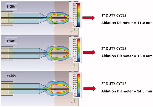
The input reflection coefficient of the antenna was continuously monitored to assure a matching better than −12 dB that corresponds to a reflected less than 10%. Depth of insertion was decided in order to produce the maximum coagulation volume inside the tissue reducing the heat dissipation between the antenna and the environment. Different applications need different depths and different needle sizes. In this work we evaluate this new device with an insertion depth of 18 mm in the tissue, that it could be changed in range of 20% with a tolerable mismatch: our future papers will analyse with accuracy the other effects correlated to the insertion depth. The procedures were tested using three protocols to determine which protocol produces the best ablation sizes while minimizing operating phase times and avoiding device overheating. The CPh was set at 30 s and was not varied for each protocol, whereas The HPh was set at 20, 30, and 40 s, as show in .
Table 2. Protocol duty cycle.
During all the experiments, we monitored the liver surface (capsule) temperature by using a thermal camera and the supporting aluminum cylinder temperature by using a thermocouple (). We tested the three simulated protocols separately, and measured ablation diameters at the end of each test. Finally, we tested the entire sequence of hepatic resection comprising eight sequential ablations on predefined equidistant (10 mm) points.
Results
CST simulations
shows the HPh results on the three references points of obtained through CST analysis.
Figure 3. Temperature evolution results obtained through the CST simulator.
It is worth noting that the probe at point 1 is subject to more heat sink effect caused by conduction as it is in direct contact with the metal part. In contrast, point 2, being closer to the antenna and not in direct contact with the metal armor, dissipates heat only because of the effect of convection with the air on the surface of the parenchyma, thus resulting in higher temperatures at the end of the procedures.
At the end of HPh, we collected the corresponding ablation diameters on the liver surface, considering the region of tissue enveloped by the 60 °C isothermal curve (blue), as shown in . This threshold was selected to match a secure coagulative necrosis temperature.
Figure 4. Isothermal distributions on the Y–Z plane of protocols coupled thermal EM simulations.
SFS simulations
The HPh behavior at the end of the CST simulation was assumed as the initial condition for SFS CPh simulation. By using the SFS software, we obtained the CPh temperature evolution shown in and at points 1 and 4 (), respectively.
Figure 5. Temperature evolution at Point 1() for different protocols (HPh: red boxes, CPh: blue boxes).
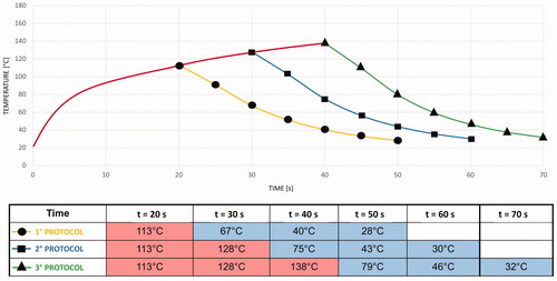
Figure 6. Temperature evolution at Point 4 () for different protocols (HPh: red boxes, CPh: blue boxes).
The red curve in represents the thermal data captured during the HPh by using the CST simulator. As expected, the needle temperature rapidly decreased because its thermal inertia was very low. The aluminum cylinder, with higher thermal inertia, showed a gradual increase in temperature during the application of all the protocols.
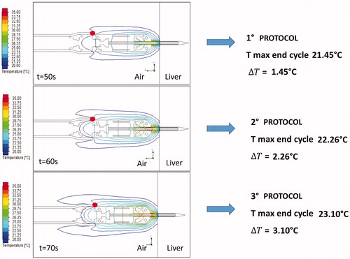
At the end of the CPh, the thermal field showed a symmetrical polar distribution around the Z axis. shows the thermal behavior results for the three simulated protocols, highlighting the maximum temperature and temperature gradient at point 4.
Figure 7. Isothermal distributions on the Y–Z plane of the thermal field on SFS.
Ex vivo test results
As a result of localized overheating, uncooled applicators showed limitations for the continuous power supply. In this study, the metallic mass of the device worked as an efficient heat sink and thermal stabiliser, increasing the durability and resilience of the applicator even at high power levels.
By using the newly developed device, we performed 120 ablations without any apparent degradation and input impedance mismatch. Single ablation procedures by using the three protocols were repeated eight times (total n = 24), and eight sequential ablations were repeated four times (total n = 96).
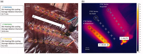
The superficial ablation diameters for single and sequential procedures were almost the same because they essentially depend on the energy transferred to the tissue during the power-on phase of each protocol. For the first protocol (2.4 KJ pulse), the mean diameter was 9.2 mm with a variance of 0.22 mm; for the second protocol (3.6 KJ pulse), the mean diameter was 12.7 mm with a variance of 0.35 mm; and for the third protocol (4.8 KJ pulse), the mean diameter was 14.6 mm with a variance of 0.58 mm (). The diameters were also confirmed by matching the measurements of the 60 °C isothermal line on the thermal camera images with an error range of ±0.25 mm (). The difference between mean diameter values measured by thermal camera and the manually measured values is related to the difficulties in estimating optically the edge of coagulation.
Figure 8. Protocols ablation series: (a) difference in the superficial radius dimensions in each protocol; (b) Thermal image at the end of eight sequential ablations using the 1°-protocol.
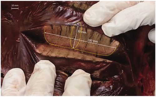
After each sequential ablation procedure, the liver was cut along the predefined resection line to assess measurements and quality of ablation. For the 1°, 2°, and 3° protocols, we measured coagulated areas of approximately 90 × 25 mm, 100 × 30 mm, and 105 × 33 mm, respectively.
As a first gross assessment, a surgeon evaluated the quality of the coagulated area. The resection line was free of tissue charring and carbonization, and presented the best homogeneous area of well coagulated tissue with 2° protocol application ().
Figure 9. Coagulated area after eight ablations: dimensional references refer to the 2° protocol.
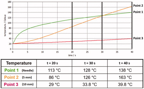
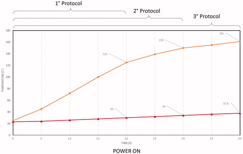
Temperature measurements acquired through the thermal camera were collected for each protocol on single and sequential ablations to validate CST simulations. The temperature was measured at points 2 and 3 (). During the application of the first, second, and third protocols, the temperature ranges at point 2 were 20–125, 20–150, and 20–161 °C, respectively. During the application of the first, second, and third protocols, the temperature ranges at point 3 were 20–30, 20–34, and 20–37.8 °C, respectively. However, the maximum temperature varied for different protocols, and the temperature gradient measured at points 2 and 3 was the same for all the protocols ().
Figure 10. Mean statistical temperature evolution measured using the thermal camera: orange and red curves represent temperature evolution at points 2 and 3, respectively.
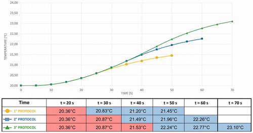
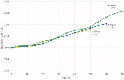
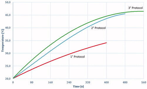
shows the average temperature evolution measured using the thermocouple at point 4 () for different protocols.
Figure 11. Average temperature evolution measured using the thermocouple: the yellow, blue, and green lines represent the temperature evolution for 1°, 2°, and 3° protocols.
Discussion
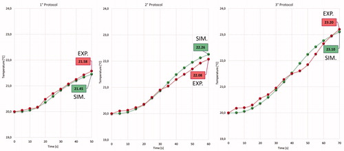
Our main objective was to validate the electromagnetic and thermal models of the developed uncooled MW tissue coagulator, confirming its fundamental characteristics of safety, effectiveness, and robustness, and defining the optimal protocol to achieve the best coagulative results. Accordingly, we compared the simulated and experimental thermal behaviors at points 2 and 3 of , as shown in .
Figure 12. Comparison of results of simulated protocols at points 2 and 3 for the Power-ON phase.
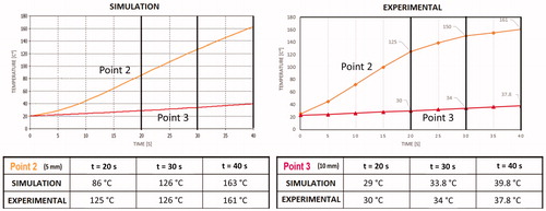
The discrepancies between simulated and experimental behaviors at point 2 can be explained based on the high complexity of the heating process. Indeed, numerical modeling could not simulate liquid migration and tissue-state changes (e.g. vaporization). However, the thermal behavior at point 3 () is well-predicted because these phenomena do not occur in the metal parts of the applicator.
Moreover, at point 4 (), the simulated and experimental curves almost perfectly match. This result validates the simplification assumed for the numerical simulation and highlights the quality of the coupled simulation using CST and SFS ().
Figure 13. Comparison between results of simulated protocols (green) and experimental protocols (red) at Point 4.
Regarding the surgical aspects, the new MW tissue coagulator has dimensions compatible with laparoscopic and robotic interventions because it can be inserted into a conventional laparoscopic trocar of 12-mm diameter. The capability of the steerable head is an essential innovation that allows surgeons to perform an entire surgical resection by using the same trocar entrance, avoiding multiple percutaneous insertions [Citation28]. The steerable head with 1 DOF and the added rotational DOF along the trocar’s axis could be very helpful during laparoscopic and robotic procedures. In the near future, to increase the device usability and flexibility, there may be a need to add another DOF similar to that of other surgical tools used in literature [Citation29].
Following surgical team requirements, the tool has the main characteristic of not exceeding 70 °C at the joint surface despite the absence of forced internal cooling. The reduced heating of the device is due to the optimal thermal coupling between the steering head and supporting aluminum tube that allows an efficient transfer of heat from the needle to the outside of the trocar. This is supported by the fact that a pulsed procedure is employed to achieve the best duty cycle between the ablation and cooling phases.
The lack of cooling allows a dramatic reduction of the mechanical complexity of the device as already described, making it the ideal tool for laparoscopic intervention and integration with a robotic platform. The maximum temperature allowed for the steerable head was set at 60 °C to leave a wide margin of safety for adjacent organs and prevent iatrogenic internal damage during surgery. As shown in and , during the power-on phase, while hepatic surface temperature is very high (reaching 161 °C at point 2 when using the third protocol), the surface temperature of the aluminum cylinder does not exceed 50° C even after multiple ablation series because the temperature behavior tends to reach thermal equilibrium.
Figure 14. Temperature evolution during the eight sequential ablation measured on point 4 (): 1° protocol (Red); 2° protocol (Blue); 3° protocol (Green).
Another important safety issue is related to the lateral spreading of heat. The tool should be able to create a coagulated area of approximately 10-mm diameter without excessively heating the adjacent parenchyma to preserve a healthy liver. and show hepatic thermal results during the ex vivo tests, showing that while the needle registered a very high temperature gradient (up to 161 °C in a few seconds), creating an effective mean coagulated area of approximately 10 mm, the temperature at 10 mm from the needle centre does not exceed 40 °C during the entire heating process. This temperature level is perfectly compatible with optimal cell viability. This could be verified in the future by using in vivo tests.
During liver surgery, sparing of the parenchyma is considerably important to preserve as much of the liver as possible, guarantee liver efficiency, and make subsequent interventions. Within the limits of a no perfused model, the dimensions of the coagulated areas demonstrated the effectiveness of the device during the three protocols and ablation series. The tool, used at its maximum power of 120 W, achieved a homogeneous coagulated area with a mean diameter of 10 mm for the single ablation test and mean of 30 × 100 mm in the sequential ablation tests. These values are in line with the requested dimensions obtained from the surgical team. Specimen examination along the resection line showed that the MW tool generated a homogeneous coagulated area. We observed an incipient carbonization of tissue near the antenna shaft only when using the third and longest protocol; this possibly indicates slightly excessive delivered energy. This phenomenon could disappear in a perfused tissue owing to the heat-sink effect.
We expect that this ex vivo result will be confirmed through an in vivo test, demonstrating the possibility of combining a good haemostatic effect, achieved in a short time, with a surgical safety margin to achieve a very low lateral damage of a healthy liver.
Conclusions
We demonstrated that numerical electromagnetic and thermal simulations are effective in developing a MWA device optimized for laparoscopic and robotic procedures. An exhaustive ex vivo test on a bovine liver allowed validation of the numerical results in the case of both spot and sequential ablations in a nonperfused tissue. We expect that on the perfused liver, the results could be relatively similar because the high impulsive energy achieved in the power-on phase of the needle is capable of causing an almost instantaneous coagulation despite the heat-sink effect produced by the vasculature. Future work will include the following:
the modeling of a needle to immerse in a time-variant perfused tissue;
a series of ex vivo tests on excised bovine or swine liver, where the perfusion is sustained using an external pump;
in vivo testing on pigs by using a device integrated on a robotic platform.
The new MW device is easily integrated with laparoscopic and robotic tools, and shows a thermal dynamic behavior that is compatible with a safe transection procedure capable of creating a stable, effective, and reproducible coagulated area for bloodless liver excision.
Acknowledgements
This work was supported by Regione Toscana in the framework of the IMEROS Project within the ‘PAR FAS 2007–2013, bando FAS Salute 2014’.
Disclosure statement
No potential conflict of interest was reported by the authors.
References
- Forner A, Reig M, Bruix J, et al. Hepatocellular carcinoma. Lancet. 2018;391:1301–1314.
- Toso C, Mentha G, Kneteman NM, et al. The place of downstaging for hepatocellular carcinoma. J Hepatol. 2010;52:930–936.
- Cha C. Surgical therapy for hepatocellular carcinoma: formulating a rational approach. J Clin Gastroenterol. 2013;47:S30–S36.
- Qi X, Tang Y, An D, et al. Radiofrequency ablation versus hepatic resection for small hepatocellular carcinoma: a meta-analysis of randomized controlled trials. J Clin Gastroenterol. 2013;48:1–7.
- Omata M, Cheng AL, Kokudo N, et al. Asia–Pacific clinical practice guidelines on the management of hepatocellular carcinoma: a 2017 update. Hepatol Int. 2017;11:317–370.
- Korean Liver Cancer Study Group (KLCSG) and National Cancer Center, Korea (NCC) KLCSG-NCC Korea practice guideline for the management of hepatocellular carcinoma. Gut Liver. 2014;9:267–317.
- Jennifer SA, Catherine T. Frenette management of hepatocellular carcinoma: current status and future directions. Gut Liver. 2015;9:437–448.
- Roayaie S, Jibara G, Tabrizian P, et al. The role of hepatic resection in the treatment of hepatocellular cancer. Hepatology. 2015;62:440–451.
- Vitale A, Burra P, Frigo AC, et al. Survival benefit of liver resection for patients with hepatocellular carcinoma across different Barcelona Clinic Liver Cancer stages: a multicentre study. J Hepatol. 2015;62:617–624.
- Poon RT, Fan ST, Lo CM, et al. Improving survival results after resection of hepatocellular carcinoma: a prospective study of 377 patients over 10 years. Ann Surg. 2001;234:63.
- Di Carlo I. (Ed.). Open laparoscopic and robotic hepatic transection. Tools and methods. Springer; 2012.
- Otsuka Y, et al. What is the best technique in parenchymal transection in laparoscopic liver resection? Comprehensive review for the clinical question on the 2nd International Consensus Conference on Laparoscopic Liver Resection. J Hepatobiliary Pancreat Sci. 2015;22:363–370.
- Kaneko H, Otsuka Y, Tsuchiya M, et al. Application of devices for safe laparoscopic hepatectomy. HPB. 2008;10:219–224.
- Curro G, Bartolotta M, Barbera A, et al. Ultrasound-guided radiofrequency-assisted segmental liver resection. A new technique. Ann Surg. 2009;250:229–233.
- Sasaki K, Matsuda M, Hashimoto M, et al. Liver resection for hepatocellular carcinoma using a microwave tissue coagulator: experience of 1118 cases. WJG. 2015;21:10400.
- Zhou XD, Tang ZY, Yu YQ, et al. Microwave surgery in the treatment of hepatocellular carcinoma. Semin Surg Oncol. 1993;9:318–322.
- Tabuse K, Katsumi M, Kobayashi Y, et al. Microwave surgery: hepatectomy using a microwave tissue coagulator. World J Surg. 1985;9:136.
- Brace CL. Microwave tissue ablation: biophysics, technology, and applications. Critic Rev Biomed Eng. 2010;38:1.
- Biffi Gentili G, Ignesti C. Dual applicator thermal ablation at 2.45 GHz: a numerical comparison and experiments on synchronous versus asynchronous and switched-mode feeding. Int J Hyperthermia. 2015;31:528–537.
- Berber E, Akyildiz HY, Aucejo F, et al. Robotic versus laparoscopic resection of liver tumours. HPB (Oxford). 2010;12:583–586.
- Reuter NP, Martin RCG. Microwave energy as a precoagulative device to assist in hepatic resection. Ann Surg Oncol. 2009;16:3057–3063.
- Francone E, et al. Precoagulation-assisted parenchyma-sparing laparoscopic liver surgery:rationale and surgical technique. Surg Endosc. 2017;31:1354–1360.
- Percivale A, et al. Microwave assisted liver resection: clinical feasibility study and preliminary results. Minerva Chir. 2012;67:415–420.
- Adebar TK, Greer JD, Laeseke PF, et al. Methods for improving the curvature of steerable needles in biological tissue. IEEE Trans Biomed Eng. 2016;63:1167–1177.
- Lum MJ, Trimble D, Rosen J, et al. Multidisciplinary approach for developing a new minimally invasive surgical robotic system. The First IEEE/RAS-EMBS International Conference on Biomedical Robotics and Biomechatronics; 2006 Feb 20; Pisa, Italy. p. 841–846.
- Costa JR, Gutermann J. Introduction to antenna and near field simulation in CST microwave studio software. Lisbon, IT: IEEE Communications Society Portugal Chapter; 22 March 2010.
- Matsson JE. An introduction to solidworks flow simulation. SDC Publications; 2013.
- Shiina S, Hata Y, Niwa Y, et al. Multiple-needle insertion method in percutaneous ethanol injection therapy for liver neoplasms. Gastroenterol Jpn. 1991;26:47–50.
- Seibold U, Kubler B, Hirzinger G. Prototype of instrument for minimally invasive surgery with 6-axis force sensing capability. ICRA 2005. Proceedings of the 2005 IEEE International Conference on Robotics and Automation; Barcelona, Spain; 2005.