
Abstract
Purpose: Tissue-mimicking phantoms (TMPs) are synthetic materials designed to replicate properties of biological tissues. There is a need to quantify temperature changes following ultrasound or magnetic resonance imaging-guided high intensity focused ultrasound (MR-HIFU). This work describes development, characterization and evaluation of tissue-mimicking thermochromic phantom (TMTCP) for direct visualization and quantification of HIFU heating. The objectives were to (1) develop an MR-imageable, HIFU-compatible TMTCP that reports absolute temperatures, (2) characterize TMTCP physical properties and (3) examine TMTCP color change after HIFU.
Methods and materials: A TMTCP was prepared to contain thermochromic ink, silicon dioxide and bovine serum albumin (BSA) and its properties were quantified. A clinical MRI-guided and a preclinical US-guided HIFU system were used to perform sonications in TMTCP. MRI thermometry was performed during HIFU, followed by T2-weighted MRI post-HIFU. Locations of color and signal intensity change were compared to the sonication plan and to MRI temperature maps.
Results: TMTCP properties were comparable to those in human soft tissues. Upon heating, the TMTCP exhibited an incremental but permanent color change for temperatures between 45 and 70 °C. For HIFU sonications the TMTCP revealed spatially sharp regions of color change at the target locations, correlating with MRI thermometry and hypointense regions on T2-weighted MRI. TMTCP-based assessment of various HIFU applications was also demonstrated.
Conclusions: We developed a novel MR-imageable and HIFU-compatible TMTCP to characterize HIFU heating without MRI or thermocouples. The HIFU-optimized TMTCP reports absolute temperatures and ablation zone geometry with high spatial resolution. Consequently, the TMTCP can be used to evaluate HIFU heating and may provide an in vitro tool for peak temperature assessment, and reduce preclinical in vivo requirements for clinical translation.
Introduction
Tissue-mimicking phantoms (TMPs) are synthetic materials designed to mimic the properties of biological tissues, and are commonly used to evaluate, calibrate, characterize and assess medical devices, including thermal therapy applicators. TMPs are also used in preclinical research as an alternative to ex vivo tissues and organs, as TMPs possess several advantages. These include superior availability and shelf life, high structural uniformity and customizability. In addition, TMPs provide a test environment for quality assurance (QA), operator training and optimization of therapy protocols without necessitating animal or human patients.
High intensity focused ultrasound (HIFU) is a therapeutic modality useful for a wide variety of clinical applications, and is capable of noninvasive, volumetric tissue heating to induce targeted and localized thermal ablation, mild hyperthermia and/or mechanical fractionation [Citation1–4]. HIFU is generally performed under magnetic resonance imaging (MR-HIFU) or ultrasound imaging (US-HIFU) guidance [Citation5–9]. A suitable TMP for HIFU applications should be MR and US compatible and imageable, and possess similar physical, acoustic and thermal properties as human tissues. These properties include mass density, speed of sound, acoustic attenuation, thermal conductivity and thermal diffusivity. An ideal TMP to characterize and optimize HIFU devices, parameters and sonication protocols, and to perform QA, should also provide a direct indication of temperature elevation or absolute temperature as well as recapitulate volumetric, spatial heating patterns.
Several HIFU TMP formulations based on agar, gelatin, or polyacrylamide have been reported that often include additives to adjust TMP thermal and acoustic properties to be comparable to human soft tissues [Citation10–15]. For example, the TMP acoustic attenuation and speed of sound may be adjusted via the addition of silicon dioxide particles, condensed milk, bovine serum albumin (BSA), corn syrup, glass beads, intralipid, graphite or propanol [Citation16–19]. Nevertheless, phantoms made with these materials typically do not provide a direct means for quantifying absolute temperatures or changes in temperature during or following HIFU heating.
Accurate and quantitative evaluation of HIFU-generated temperature elevation and heating patterns generally require the insertion of thermocouples or fiber-optic temperature probes, or the use of MRI-based temperature mapping methods [Citation8,Citation20–22]. However, probe placement at or adjacent to the HIFU focus interferes with the acoustic field, and can disrupt HIFU energy delivery and cause damage to the probe tip, resulting in inaccurate measurement of temperature [Citation23,Citation24], necessitating the need for thermal models to estimate HIFU focal zone temperatures. On the other hand, MRI thermometry is not always available, feasible or cost-effective, and US-HIFU devices or preclinical HIFU devices may not be MRI compatible, prohibiting the use of MRI for immediate and direct temperature assessment.
One approach to visualize thermal lesions in a TMP is by incorporation of BSA due to its coagulation and characteristic opacification upon heating (also observed via changes in MRI signal intensity and/or T2 relaxation time) [Citation17,Citation25,Citation26]. While the coagulation threshold temperature can be adjusted by altering the pH of the phantom [Citation17], BSA-based TMPs generally do not report on absolute temperatures.
Thermochromic materials possess the ability to change color based on temperature. The change in color can be permanent or reversible, and with or without intermediate stages (colors). Several different materials may be used to achieve color changes over a range of temperatures including liquid crystals, leuco dyes or inks [Citation27–29]. For example, a heat sensitive phantom utilizing thermochromic liquid crystals has been recently developed for HIFU QA [Citation30]. This phantom consists of a layer of thermochromic material on top of an absorbing disc, but is not tissue-mimicking and does not inform on volumetric spatial heating patterns. In addition, a tissue-mimicking thermochromic phantom (TMTCP) material that reports on HIFU heating patterns has been described [Citation31]. This TMTCP incorporates a thermochromic material to produce a reversible change upon heating. However, the reversible nature of the color change requires rapid analysis in order to inform on temperatures before color reversal. Furthermore, the color change threshold (50 °C) of this phantom is low for thermal ablation and the color change process is affected by a hysteresis effect.
Our team previously reported a TMTCP gel formulation that permanently changes color upon heating. We characterized its ability to provide quantitative and absolute measurements over a range of temperatures and evaluated its applicability in radiofrequency ablation [Citation27,Citation28]. In this study, we tailored the TMTCP gel formulation for HIFU use and evaluated its applicability in characterization of HIFU devices, sonication parameters and heating protocols. Specifically, the objectives of this study were to: (1) Develop an MR-imageable and HIFU-compatible TMTCP material; (2) characterize its physical, thermal, and acoustic properties as well as its pre- and post-HIFU T2 relaxation time; and (3) examine TMTCP performance by analyzing HIFU-mediated heat deposition and spatial distribution through MRI and visual assessment of color change using two different HIFU systems.
Materials and methods
TMTCP preparation
The acrylamide-based TMTCP material was prepared as previously described with the addition of silicon dioxide and BSA to impart ultrasound attenuation and MRI signal effects (coagulation of BSA results in T2 relaxation time change) [Citation27]. Briefly, degassed, de-ionized water was mixed under a fume hood with an aqueous solution of 40% (w/v) acrylamide/bis-acrylamide (VWR International, Secaucus, NJ). Thermochromic ink (MB Magenta NH 60 °C concentrate, 5% v/v; LCR Hallcrest, LLC, Glenview, IL) that changes color from white to magenta was added to this mixture. BSA (3% w/v; Sigma Aldrich, Milwaukee, WI), and silicon dioxide (1.1% w/v; Sigma Aldrich, Milwaukee, WI) were also added. Finally, ammonium persulfate (APS, Sigma Aldrich, Milwaukee, WI) and N, N, N’, N’-tetramethylethylenediamine (TEMED, Sigma Aldrich, Milwaukee, WI) were added to initiate polymerization and to act as a catalyst, respectively. All ingredients were kept and mixed at room temperature, and the solution was stirred until ingredients were completely dissolved (∼15–20 min). This solution was then poured into 200 mL cylindrical molds, 706 mL Petri dishes, or 4 mL glass vials, sealed, cooled overnight and kept at 4 °C until use. Preparation of a TMTCP batch generally took 30–40 min. The standard TMTCP formulation for HIFU use is summarized in .
Table 1. TMTCP formulation for HIFU experiments.
Measurement of TMTCP properties
In preparation for ultrasonic attenuation and speed of sound measurements, TMTC phantoms were formed inside custom-constructed, 200 mL cylindrical plastic molds with taut, acoustically transparent Mylar sheets secured at each end. Speed of sound and attenuation measurements were performed using an ultrasonic time-delay spectrometry (TDS) system as previously described by Gammell et al. [Citation32]. Briefly, a 13-mm diameter, 10-MHz planar source transducer (Valpey Fisher Corp., Hopkinton, MA) transmitted a down-swept sine wave signal from 10 to 0 MHz in 0.1 s. A 6-mm diameter, 5-MHz planar receiving transducer (Valpey Fisher Corp., Hopkinton, MA), located 30 cm from the transmitter, distinguished arrivals with different propagation delays by their frequency offset relative to the transmitted signal using a narrowband swept filter.
The attenuation (insertion loss) was measured in three TMTCP samples, as described by Madsen et al. [Citation33]. The spectra (in dB) transmitted through the custom molds filled with deionized water and TMTCP material were subtracted to eliminate reflection losses at the anterior and posterior Mylar interfaces, the latter located 1 cm from the receiver. Speed of sound measurements was obtained in the same three TMTCP samples by using the temperature dependent speed of sound in water as the substitution reference [Citation34]. Measurements were taken at four spatially separate locations in the phantom (5 mm apart) at ambient temperature (26.3 °C), and each signal was averaged 64 times.
Thermal conductivity and thermal diffusivity of TMTCP were measured from three samples using a thermal property analyzer (KD-2 Pro, Decagon Devices, Pullman, WA). In addition, mass density of the TMTCP material was determined using the Archimedes’ principle. Briefly, phantom samples (N = 5; 2 cm diameter) cut from the 200 mL cylindrical phantoms were submerged in water and the density was measured in triplicate using a balance equipped with a density measurement kit (Mettler Toledo, VWR International, Batavia, IL). Finally, acoustic impedance was determined by multiplying the density and the speed of sound of TMTCP material [Citation35]. For all property measurement results, the average ± one standard deviation is provided.
Characterization of TMTCP color change
Color vs. temperature calibration of the TMTCP material was performed as previously described [Citation28]. Briefly, capped glass vials containing 4 mL of TMTCP gel were submerged in a water bath in triplicate and incubated for 10 min at temperatures ranging from 35 to 70 °C, as measured by calibrated optical temperature probes (diameter = 0.56 mm, Luxtron 3100, LumaSense Technologies, Santa Clara, CA). The vials were subsequently removed from the water bath and allowed to cool to room temperature (25 °C) before color analysis.
Vials containing TMTCP gel were then photographed at a standard color temperature of 5500 K under controlled lighting conditions using a portable photography light box (SANOTO 16 × 12 in. Softbox MK40, Whittier, CA) and a Canon Digital EOS T5 SLR camera. The photographs were color-corrected using the white background of the photography box as a reference prior to extraction of red, green and blue (RGB) color channel values using a custom MATLAB script (R2013a, MathWorks, Natick, MA). The RGB components were plotted as a function of temperature to produce a calibration curve.
Clinical and preclinical HIFU systems
A clinical MR-HIFU system Sonalleve version 2 (Profound Medical Inc., Mississauga, Canada) was used for volumetric HIFU exposures (). The Sonalleve version 2 system delivers spatiotemporally controlled ultrasound energy and consists of a therapy control workstation, RF generators and control electronics, and a treatment table that houses the positioning system and a 256-element phased-array ultrasound transducer (14 cm focal length). The transducer is immersed in an oil tank, sealed with a thin, plastic, acoustically transparent membrane to allow HIFU beam propagation to the target (.
Figure 1. HIFU systems utilized in TMTCP experiments. (A) The Sonalleve V2 clinical tabletop MR-HIFU system. (B) The TIPS preclinical benchtop US-HIFU system.
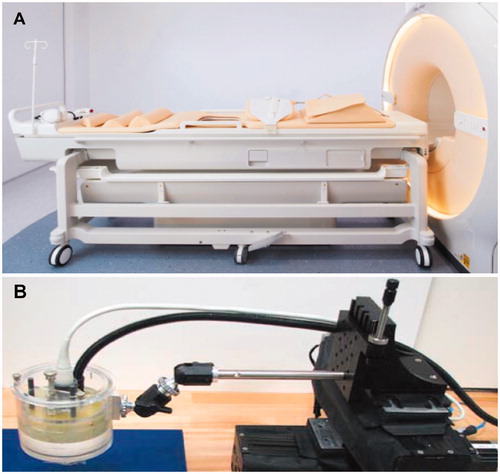
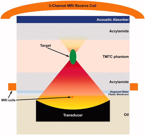
Figure 2. Schematic representation (not depicted to scale) of HIFU targeting in TMTCP using the Sonalleve V2 clinical MR-HIFU system. A similar configuration, but without the MRI coils, was used with the TIPS preclinical US-HIFU system.
A preclinical benchtop US-HIFU system (Therapy Imaging Probe System [TIPS], Philips Research, Cambridge, MA) was also used for HIFU exposures (). The TIPS system includes an 8-element annular ultrasound transducer (8 cm focal length) as well as a motion control system capable of precise spatial targeting.
Experimental setup and HIFU sonication parameters
TMTC phantoms (diameter 15 cm, height 4 cm) were prepared for HIFU sonications. These TMTCPs were positioned on the clinical MR-HIFU treatment table between two pieces of acrylamide gel at room temperature (. Acrylamide has relatively low ultrasound attenuation (0.08–0.14 dB/cm at 1 MHz) and has been proposed as a coupling media for focused ultrasound therapy [Citation36]. Degassed water and an acrylamide layer were used for acoustic coupling between the plastic membrane and the TMTC phantom, as well as between the TMTC phantom and an acoustic absorber (. Nine circular regions of 12 mm in diameter were targeted, using sonication frequency of 1.2 MHz, acoustic power of 160 W and electronic steering of the HIFU focus along concentric circle trajectories [Citation8]. A cool-down time of 5 min was applied after each sonication, and the transducer positioning system was utilized to move between the targets. A temperature feedback algorithm with a target mean temperature of 65 °C was applied, resulting in consistent sonication duration of approximately 40 s for all sonications.
Additionally, we performed pulsed boiling histotripsy (BH) sonications using acoustic power of 450 W, 10 ms long pulses and 30 pulses per trajectory point. BH is a HIFU technique that is capable of precise mechanical fractionation of target tissue with minimal surrounding heating [Citation2,Citation3,Citation37]. Furthermore, as representative examples, HIFU sonications were performed in TMTCP embedded with either a rubber blood vessel-mimic with water flow or plastic rib mimic (VeroWhitePlus, Stratasys, Ltd., Edina, MN; acoustic attenuation = 3.0 dB/cm at 1 MHz, speed of sound = 2539 m/s) [Citation38]. The blood vessel-mimic was created using Penrose tubing, while the rib-mimic was created by using a CT-scan -based 3D printed section of human ribcage. The mimics were placed within the TMTC phantom mold during preparation, after which the TMTCP was allowed to gel, as described earlier [Citation39].
For experiments on the TIPS preclinical HIFU system, TMTCPs were sandwiched between two pieces of acrylamide gel, fixed onto an acoustic absorber and positioned underneath the TIPS transducer. This allowed for acoustic coupling by a thin layer of degassed water. Sonications were then performed using ultrasound frequency of 1.0 MHz, electric power of 30 W and sonication durations of 60, 120 and 180 s. For each duration setting, four separate locations (2 cm apart; square pattern) were targeted and the motion control system was utilized to move between targets.
Post-HIFU, we made multiple cuts with a surgical monofilament suture, prudently, to expose the phantom layer by layer. Once the sonicated region was exposed, we also made a transverse cut (90°), exposing the volumetric shape of the sonicated region.
MRI-based quantification of temperatures and T2 relaxation times
For HIFU exposures using the Sonalleve version 2 clinical MR-HIFU system, a clinical 1.5 T MRI scanner (Achieva, Philips, Best, Netherlands) was used for exposure planning, real-time thermometry utilizing the proton resonance frequency shift (PRFS) method [Citation40], and to visualize sonicated volumes using T2-weighted imaging and quantitative T2 mapping. A clinical 5-element RF receive coil was used in the experiments. The coil consists of two elements integrated into and around the acoustic window in the treatment table (below the TMTCP), and of another three elements positioned above the TMTCP (.
Standard T1- and T2-weighted MRI were acquired for planning the target locations in TMTCP and to visualize sonicated volumes, respectively, while multi-plane thermometry was performed during HIFU sonications using a dynamic, RF-spoiled, fast field echo-echo planar imaging (FFE- EPI) sequence. Two imaging slices were acquired; one coronal and one sagittal slice automatically positioned perpendicular and parallel to the beam axis, with the slices crossing at the center of the target region. The thermometry sequence parameters were: TR 54 ms, TE 19 ms, matrix size 144 × 144, field-of-view (FOV) 200 × 200 mm2, slice thickness 7 mm and flip angle 19.5°, resulting in voxel size of 1.4 × 1.4 × 7.0 mm, with an acquisition time of 2.5 s per dynamic frame.
Before and after TMTCP water bath heating at 65 °C for 2 h (to trigger complete and uniform color change and BSA coagulation), T2 maps of four cylindrical 200 mL phantoms were acquired to quantify pre- and post-heating MRI T2 relaxation times using a two-channel clinical RF receive coil (SENSE Flex M, Philips, Best, the Netherlands) at two different field strengths (1.5 T and 3.0 T, Achieva, Philips, Best, the Netherlands). T2 maps of coronal stacks consisting of 6 slices per phantom were acquired using a multi-echo 2D turbo spin echo pulse sequence with the following parameters: 16 echo times ranging from 50 to 450 ms, FOV 100 × 100 mm2, in-plane acquisition resolution 2.2 × 4.0 mm2, slice thickness 5 mm with a slice gap of 3.0 mm, TR 3400 ms, two signal averages and a flip angle of 90°.
Results
Properties of TMTCP
Unheated TMTCP mass density, speed of sound, acoustic attenuation, acoustic impedance, thermal conductivity and diffusivity and T2 relaxation times were measured (). Pre-heating TMTCP properties were found to be similar to those in human soft tissues such as liver, kidney, brain and muscle [Citation41,Citation42]. Post-heating T2 relaxation times were measured to be 97 ± 5 ms at 1.5 T and 86 ± 5 ms at 3.0 T.
Table 2. Unheated TMTCP properties.
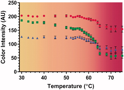
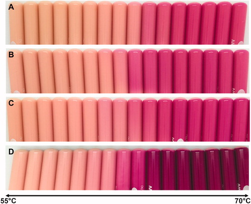
In addition, TMTCP color change was assessed over a range of temperatures. The greatest color change occurred above 64 °C (. Color changes were not detected for temperatures below 45 °C, while there was a gradual change between 45 and 64 °C. Additionally, shows color vs. temperature calibration curves derived by quantifying the RGB color channel values from TMTCP photographs. The curves are overlaid on a computer-generated color swatch, which aids visual assessment of temperature change in the TMTCP. There was minimal change in color intensity at temperatures between 30 and 45 °C and between 65 and 75 °C, with the green color channel displaying the greatest dynamic range between 30 and 75 °C.
Figure 3. Color of TMTCP samples after water bath heating to temperatures between 30 and 75 °C. Color changes are visible after incubating at temperatures above 45 °C.
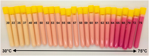
Figure 4. Color vs. temperature calibration curves derived by quantifying RGB-color intensity values of the TMTCP samples as a function of temperature between 30 and 75 °C, overlaid on a computer-generated color swatch. The color swatch aids visual assessment of temperature change in the TMTCP. The circles, squares and triangles represent red, green and blue color channels, respectively. The error bars indicate one standard deviation of intra-phantom or analysis-based variability, not inter-phantom variability.
Formulation dependence of TMTCP color change
TMTCP color post-heating was examined for formulations with or without silica, BSA or sodium chloride that provide ultrasound attenuation, MR-imageability and electrical conductivity, respectively. demonstrates the effect of different phantom formulation ingredients on TMTCP color change properties. Our standard formulation () demonstrated substantial color change at temperatures above 64 °C (). The formulation without sodium chloride demonstrated greater color change at temperatures above 63 °C, with similar color as the standard formulation at temperatures between 55 and 70 °C (). Phantom formulation without silica also revealed the greatest color change at 63 °C (). The formulation without BSA demonstrated its greatest change in color at 62 °C, as well as the highest color intensity of all TMTCP formulations ().
Figure 5. TMTCP color change as a function of temperature (1 °C increments) and phantom formulation: (A) standard formulation, (B) standard formulation without sodium chloride, (C) standard formulation without silica and (D) standard formulation without BSA.
Correspondence of TMTCP color change with MRI
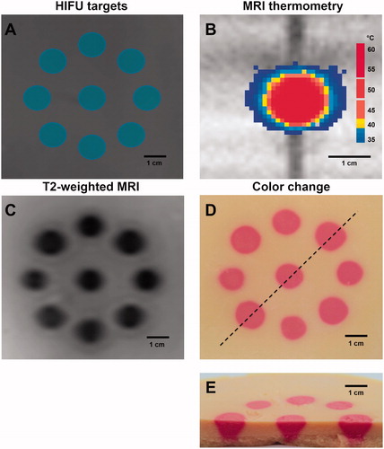
Co-localization of phantom color change, temperature elevation and T2 signal intensity changes was evaluated. Using the clinical Sonalleve version 2 MR-HIFU system, we planned a pattern with nine discrete target regions – each 12 mm in diameter (). Utilizing MRI-based temperature feedback control, HIFU sonications resulted in mean temperatures above 65 °C at the targeted regions (). Post-HIFU, nine hypointense regions approximately 12 mm in diameter were visible on T2-weighted MRI, corresponding to locations of TMTCP color changes () with high spatial precision relative to the sonication plan. Ablative temperatures were reflected in the TMTCP color, with nine regions displaying a uniform change to magenta (). Ovoid regions of color change approximately 30 mm in length were visible in the phantom along the ultrasound-axis ().
Figure 6. (A) HIFU target planning within a TMTCP performed on T1-weighted MRI. (B) Real-time MRI thermometry during HIFU sonication. (C) Hypointense regions (due to BSA coagulation) on T2-weighted MRI. (D) Photograph of TMTCP cross-section perpendicular to the HIFU beam path, showing permanent color changes with high spatial precision relative to the plan. The dashed line represents the cut to expose volumetric nature of color change. (E) Photograph of a bisected TMTCP showing color changes perpendicular to and along the HIFU beam path.
TMTCP assessment on a preclinical US-HIFU system
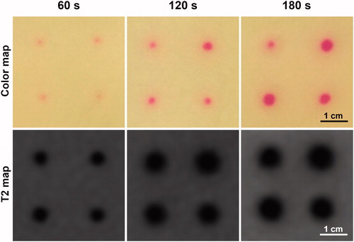
TMTCP extensibility to other devices was assessed by performing HIFU sonications on a preclinical ultrasound-guided HIFU system. Four spatial locations in each TMTCP were targeted, resulting in consistent color change at the target locations (. Sonications of 60 s produced small regions of color change at low color intensity, while 180 s sonications displayed the largest spatial dimensions and greatest intensity of color. Ovoid regions of lower T2 relaxation times, which enlarged with increasing sonication duration, were observed in 3.0 T MRI T2 maps (.
Figure 7. Representative TMTCP cross-section photographs and MRI T2 maps perpendicular to HIFU beam for 60, 120 and 180 s sonications on the TIPS US-HIFU system.
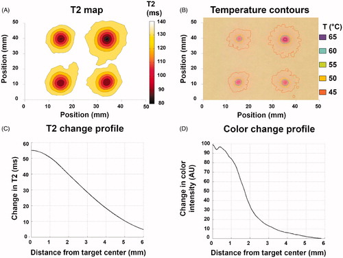
Finally, T2 relaxation time change and color change profiles were computationally derived based on T2 maps and TMTCP photographs. Representative maps for 120 s sonications are shown in for T2 and color, respectively. Temperature contours derived from the color map and temperature vs. color calibration () are also shown in . Maximum T2 change from baseline was approximately 55 ms at the center of each target region, gradually decreasing at locations further away from the targets (). Correspondingly, the green color intensity change was approximately 100 units at the center of each target, gradually reducing to zero further away from the targets (). The T2 transition from the target center to the periphery was more gradual compared to the color intensity transition.
Figure 8. (A&B) Computationally derived T2 and temperature contours based on MRI T2 maps and TMTCP color maps, respectively, following 120 s sonications on the TIPS preclinical HIFU system. (C&D) Representative examples of T2 and color change radial line profiles centered on the target. Profiles correspond to the upper left-hand-corner sonication location in A&B.
TMTCP HIFU applications
As an example of HIFU heating characterization, we performed sonications in TMTCP with the intent of producing both sparse and contiguous heating patterns () on the TIPS preclinical US-HIFU system. In both cases, we found locations with spatially precise color change and a sharp transition zone with high spatial accuracy relative to the plan, demonstrating the TMTCP utility in optimizing HIFU parameters and assessing targeting accuracy.
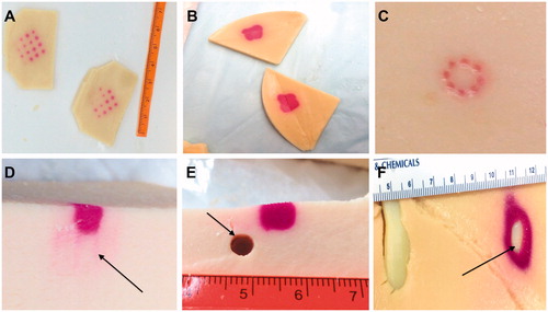
Figure 9. Example applications for TMTCP in HIFU use: (A&B) Assessment of targeting accuracy, sonication grid patterns, sparsity or contiguity of the heated region and achieved temperatures; (C) Assessment of volumetric HIFU histotripsy and the resulting heating; (D) Assessment of side lobes (arrow) and near-field heating; (E) Assessment of heating patterns in close proximity to a vessel mimic (arrow), i.e., a heat sink; and (F) Assessment of heating and heat diffusion in the presence of TMTCP-embedded rib-mimics (arrow).
As an additional example, we evaluated the TMTCP applicability in assessing BH sonications using the Sonalleve version 2 clinical HIFU system. We sonicated an 8-point circular pattern using HIFU parameters that resulted in high acoustic pressures in situ, and found localized mechanical fractionation and color changes limited to the sonication foci, with minimal extra-focal color change, consistent with BH sonications (). This suggests that TMTCP may be applied in BH parameter optimization, and in evaluation of BH mechanical fractionation and heating.
TMTCP was also utilized to visualize HIFU side lobes and near-field heating (). While the main color change region corresponded to focal energy deposition, color changes around the focal region and along the beam-axis were also observed, suggesting the role of side lobes in off-target heating, possibly due to nonrandom transducer element placement.
Finally, we showcased simplified HIFU ablation examples in close proximity to a large, high-flow vessel and of a liver segment situated under the rib cage by performing HIFU sonications in presence of TMTCP-embedded rubber vessel-mimic or plastic rib-mimic (). No color change was apparent immediately adjacent to the vessel-mimic, indicating a heat sink effect. On the other hand, substantial color changes were observed next to the rib-mimic, demonstrating that its acoustic properties, which deviate from those of TMTCP, result in extensive off-target heating ().
Overall, these results and observations highlight TMTCP applicability in characterization of different HIFU devices, applications and sonication parameters.
Discussion
The success of thermoablative therapies depends on precise spatial targeting and controlled temperature elevation within target tissues. In particular, HIFU thermal ablation has required MRI thermometry for sonication parameter optimization, assessment of targeting accuracy and assurance of appropriate temperature elevation for coagulative necrosis [Citation8,Citation43–45]. Temperature probes proximal to the HIFU focal zone have been used for ultrasound-guided HIFU applications. However, given the 3D nature of the focal acoustic pressure field and frequent utilization of volumetric heating concepts, such as electronic steering of the focal point, the accuracy of volumetric temperature estimates depends on the number of probes and their location [Citation24].
We have previously developed a TMTCP comparable to liver tissue for characterization of radiofrequency thermal ablation [Citation28]. Herein, a HIFU-compatible TMTCP was developed, its color assessed as a function of temperature, and its performance characterized on two different HIFU systems. Post-HIFU TMTCP color changes were correlated with MRI thermometry and T2 maps, demonstrating the applicability of TMTCP in MR-HIFU use.
Currently, most available TMPs cannot be used to accurately assess the spatial location and volume of the heated region post-HIFU. We witnessed an abrupt color change when TMTCP temperatures surpassed 64 °C. This observation is particularly valuable in optimizing HIFU sonication parameters for tissue thermal ablation (55–65 °C) [Citation46]. In addition, the TMTCP provides a permanent and stable change in color, allowing immediate or delayed assessment of HIFU-generated heated volumes ( and ). RGB color intensities were quantified from photographs of heated TMTCP samples (). Based on this color vs. temperature calibration, photos of TMTCP can be used for automated or semi-automated computational temperature estimates () to, e.g., validate MRI or US-based thermometry techniques.
The MRI compatibility of TMTCP is particularly valuable since a considerable number of HIFU treatments are performed under MRI guidance [Citation44,Citation46]. TMTCP formulation with BSA provides permanent T2 relaxation time changes upon HIFU heating, allowing post-HIFU MRI-based verification of ablative temperatures. TMTCP pre-heating T2 relaxation times were comparable to human kidney and brain tissues. Post-heating, 57 and 43% T2 decrease were observed at 1.5 T and 3.0 T, respectively, suggesting a wide dynamic range in T2 maps and T2-weighted MRI of the TMTCP. Accordingly, we observed BSA denaturation and corresponding T2 changes at all targeted locations that correlated spatially with regions of color change. This suggests that both MRI T2 maps and TMTCP color maps can be used to validate targeting accuracy and assess heating patterns, independent of the utilized MR-HIFU or US-HIFU device. depicts T2 and color change as a function of distance from the focus, and suggests that BSA coagulation begins at a lower temperature, and occurs more gradually than color change. However, the BSA coagulation threshold and degree of coagulation (T2 shortening) as a function of temperature or thermal dose may need to be characterized in more detail to allow for more accurate volumetric comparison and correlation of T2 maps and color maps.
HIFU sonications were also performed on a preclinical, MRI-incompatible, US-guided HIFU system without real-time thermometry capabilities to verify TMTCP applicability to other devices. We observed no appreciable TMTCP echogenicity changes on b-mode ultrasound post-heating when compared to pre-heating. For experiments in which echogenicity changes are desirable, it may be of interest to further adjust and optimize the TMTCP formulation to provide a post-heating echogenicity change. The TMTCP, however, provides quantitative information on temperatures, volumetric heating patterns and targeting accuracy via color change. This allows for cost-effective device calibration and parameter optimization for various clinical HIFU applications without the need for real-time MRI-based thermometry. Example applications may include HIFU augmentation of immunotherapy, where generation of sparse heating patterns may yield better outcomes [Citation47]. If specific temperature immune-effects are better characterized, perhaps the TMTCP may be used to optimize HIFU-assisted immunotherapies. Similarly, HIFU ablation in close proximity to critical anatomical structures may carry risk, as off-target heating may not be predictable and should be avoided [Citation21]. As showcased in this work, patient-specific, 3D-printed anatomic structure mimics embedded within a TMTCP might facilitate simulation or planning for specific high-risk HIFU applications.
TMTCP temperature vs. color assessment for modified phantom formulations was performed to provide additional flexibility for users that do not have access to an MRI scanner or do not plan to use TMTCP for radiofrequency ablation-related work. For example, by preparing TMTCP without BSA or NaCl that provide MR-imageability and electrical conductivity, respectively, the phantom manufacturing can be simplified and made more economical.
Limitations of TMTCP should be considered. First, while the TMTCP provides a gradual color change at temperatures between 45 and 63 °C, substantial color changes only occur at temperatures above 64 °C. Although beneficial in HIFU ablation assessment, the TMTCP formulation may need to be adjusted for better evaluation of mild hyperthermia and sub-ablative temperatures. Alternatively, the use of other thermochromic inks with different color and color-change properties could be considered. Second, as the TMTCP color change is permanent, TMTCPs are essentially for singular use. However, thin exchangeable and disposable TMTCP slabs can be sandwiched between reusable, anthropomorphic materials in order to reduce costs or preparation time, as demonstrated in this study. Such phantoms with ablate-able and disposable modules fitting into anthropomorphic phantoms may have roles for training and simulation, especially for MRI-guided HIFU, or US-guided RF or microwave ablation. Similarly, small TMTCP can be embedded in a larger, reusable and non-thermochromic phantom. Third, as previously described, the TMTCP only reports absolute temperatures and not the cumulative thermal dose (i.e., time-temperature relationship) that is considered a better descriptor of tissue coagulative necrosis [Citation28]. To fully assess HIFU parameters and protocols applied in the clinic, the TMTCP ambient temperature should be maintained at 37 °C during experiments. Finally, although the TMTCP acoustic attenuation was measured in this study, it may additionally be valuable to measure the relative contribution of absorption and scattering to the degree of power deposition (i.e., temperature elevation). This assessment could inform further optimization of the phantom formulation and its tissue-mimicking properties. Similarly, the phantom formulation may benefit from optimization and characterization specifically for non-thermal HIFU therapy approaches (e.g., histotripsy) by adjusting the formulation to closely match tissue properties, such as elasticity and pressure threshold for cavitation.
Conclusion
A novel MR-imageable and HIFU compatible TMTCP that permanently changes color upon heating were developed. The TMTCP facilitates characterization of HIFU devices, sonication parameters, and heating protocols without the need for real-time MRI or thermocouple-based thermometry. The HIFU-optimized TMTCP can provide quantitative information on absolute temperatures, ablation volume geometry, temperature uniformity and spatial targeting accuracy, based on TMTCP color and/or T2 change. Consequently, the TMTCP can be used to evaluate HIFU device- and sonication parameter-specific heating characteristics in a controlled, predictable and spatially uniform environment through simple visual or computational methods. Although yet to be demonstrated, such methodologies may have important training and treatment planning implications as well.
Acknowledgments
The authors thank Drs. Subha Maruvada and Yunbo Liu for characterization of TMTCP acoustic and thermal properties.
Disclosure statement
Dr. Ari Partanen is a paid consultant for Profound Medical Inc. Dr. Bradford Wood is NIH Principal Investigator on related Cooperative Research and Development Agreements HIFU-related with Philips and with Profound Medical Inc. (under negotiation). The other authors have no additional relevant conflicts of interest to disclose. The authors alone are responsible for the content and writing of the article. The mention of commercial products, their source or their use in connection with material reported herein is not to be construed as either an actual or implied endorsement of any products by the US Government nor the National Institutes of Health.
Additional information
Funding
References
- Partanen A, Yarmolenko PS, Viitala A, et al. Mild hyperthermia with magnetic resonance-guided high-intensity focused ultrasound for applications in drug delivery. Int J Hyperthermia. 2012;28:320–336.
- Eranki A, Farr N, Partanen A, et al. Boiling histotripsy lesion characterization on a clinical magnetic resonance imaging-guided high intensity focused ultrasound system. PLoS One. 2017;12:e0173867.
- Eranki A, Farr N, Partanen A, et al. Mechanical fractionation of tissues using microsecond-long HIFU pulses on a clinical MR-HIFU system. Int J Hyperthermia. 2018;34:1213–1224.
- Illing R, Kennedy J, Wu F, et al. The safety and feasibility of extracorporeal high-intensity focused ultrasound (HIFU) for the treatment of liver and kidney tumours in a Western population. Br J Cancer. 2005;93:890–895.
- Wu F, Zhou L, Chen WR. Host antitumour immune responses to HIFU ablation. Int J Hyperthermia. 2007;23:165–171.
- Huisman M, Lam MK, Bartels LW, et al. Feasibility of volumetric MRI-guided high intensity focused ultrasound (MR-HIFU) for painful bone metastases. J Ther Ultrasound. 2014;2:16.
- Kim YS, Keserci B, Partanen A, et al. Volumetric MR-HIFU ablation of uterine fibroids: role of treatment cell size in the improvement of energy efficiency. Eur J Radiol. 2012;81:3652–3659.
- Köhler MO, Mougenot C, Quesson B, et al. Volumetric HIFU ablation under 3D guidance of rapid MRI thermometry. Med Phys. 2009;36:3521–3535.
- Mikhail AS, Partanen A, Yarmolenko P, et al. Magnetic resonance-guided drug delivery. Magn Reson Imaging Clin N Am. 2015;23:643–655.
- Kim J, Kim M, Park Y. Development of an agar phantom adaptable for visualization of thermal distribution caused by focused ultrasound. Piscataway (NJ): IEEE; 2011. p. 1372–1375.
- Lai CY, Kruse D, Seo JW, et al. A phantom for visualization of three-dimensional drug release by ultrasound-induced mild hyperthermia. Med Phys. 2013;40:083301.
- Pichardo S, Kivinen J, Melodelima D, et al. Suitability of a tumour-mimicking material for the evaluation of high-intensity focused ultrasound ablation under magnetic resonance guidance. Phys Med Biol. 2013;58:2163–2183.
- Dunmire B, Kucewicz JC, Mitchell SB, et al. Characterizing an agar/gelatin phantom for image guided dosing and feedback control of high-intensity focused ultrasound. Ultrasound Med Biol. 2013;39:300–311.
- Farrer AI, Odéen H, de Bever J, et al. Characterization and evaluation of tissue-mimicking gelatin phantoms for use with MRgFUS. J Ther Ultrasound. 2015;3:9.
- Choi MJ, Guntur SR, Lee KI, et al. A tissue mimicking polyacrylamide hydrogel phantom for visualizing thermal lesions generated by high intensity focused ultrasound. Ultrasound Med Biol. 2013;39:439–448.
- Madsen EL, Frank GR, Dong F. Liquid or solid ultrasonically tissue-mimicking materials with very low scatter. Ultrasound Med Biol. 1998;24:535–542.
- McDonald M, Lochhead S, Chopra R, et al. Multi-modality tissue-mimicking phantom for thermal therapy. Phys Med Biol. 2004;49:2767–2778.
- Partanen A, Mougenot C, Vaara T. Feasibility of agar‐silica phantoms in quality assurance of MRgHIFU. AIP Conf Proc. 2009;1113(1):296–300.
- Dabbagh A, Abdullah BJ, Ramasindarum C, et al. Tissue-mimicking gel phantoms for thermal therapy studies. Ultrason Imaging. 2014;36:291–316.
- Dasgupta S, Banerjee RK, Hariharan P, et al. Beam localization in HIFU temperature measurements using thermocouples, with application to cooling by large blood vessels. Ultrasonics. 2011;51:171–180.
- Civale J, Clarke R, Rivens I, et al. The use of a segmented transducer for rib sparing in HIFU treatments. Ultrasound Med Biol. 2006;32:1753–1761.
- Rieke V, Butts Pauly K. MR thermometry. J Magn Reson Imaging. 2008;27:376–390.
- Horder MM, Barnett SB, Vella GJ, et al. In vivo heating of the guinea-pig fetal brain by pulsed ultrasound and estimates of thermal index. Ultrasound Med Biol. 1998;24:1467–1474.
- Hynynen K. The threshold for thermally significant cavitation in dog’s thigh muscle in vivo. Ultrasound Med Biol. 1991;17:157–169.
- Bouchard LS, Bronskill MJ. Magnetic resonance imaging of thermal coagulation effects in a phantom for calibrating thermal therapy devices. Med Phys. 2000;27:1141–1145.
- Brodin NP, Partanen A, Asp P, et al. A simple method for determining the coagulation threshold temperature of transparent tissue-mimicking thermal therapy gel phantoms: validated by magnetic resonance imaging thermometry. Med Phys. 2016;43:1167–1174.
- Negussie AH, Partanen A, Mikhail AS, et al. Thermochromic tissue-mimicking phantom for optimization of thermal tumor ablation. Int J Hyperthermia. 2016;32:239–243.
- Mikhail AS, Negussie AH, Graham C, et al. Evaluation of a tissue-mimicking thermochromic phantom for radiofrequency ablation. Med Phys. 2016;43:4304–4311.
- Smith C, Sabatino D, Praisner T. Temperature sensing with thermochromic liquid crystals. Exp Fluids. 2001;30:190–201.
- Qureshi F, Larrabee Z, Roth C, et al. Thermochromic phantom for therapeutic ultrasound daily quality assurance. J Ther Ultrasound. 2015;3:P72.
- Dabbagh A, Abdullah BJJ, Abu Kasim NH, et al. Reusable heat-sensitive phantom for precise estimation of thermal profile in hyperthermia application. Int J Hyperthermia. 2014;30:66–74.
- Gammell PM, Maruvada S, Harris GR. An ultrasonic time-delay spectrometry system employing digital processing. IEEE Trans Ultrason, Ferroelect, Freq Contr. 2007;54:1036–1044.
- Madsen EL, Dong F, Frank GR, et al. Interlaboratory comparison of ultrasonic backscatter, attenuation, and speed measurements. J Ultrasound Med. 1999;18:615–631.
- Marczak W. Water as a standard in the measurements of speed of sound in liquids. J Acoust Soc Am. 1997;102:2776–2779.
- Christensen DA. Ultrasonic bioinstrumentation. New York (NY): John Wiley and Sons; 1988.
- Prokop AF, Vaezy S, Noble ML, et al. Polyacrylamide gel as an acoustic coupling medium for focused ultrasound therapy. Ultrasound Med Biol. 2003;29:1351–1358.
- Canney MS, Khokhlova VA, Bessonova OV, et al. Shock-induced heating and millisecond boiling in gels and tissue due to high intensity focused ultrasound. Ultrasound Med Biol. 2010;36:250–267.
- Alles EJ, Nikitichev D, Desjardins AE, editors. Fabrication and characterisation of miniature parabolic acoustic lenses. 2015 IEEE International Ultrasonics Symposium (IUS). Piscataway (NJ): IEEE; 2015.
- Farr N, Partanen A, Kothapalli SVVN, et al. Tissue-mimicking thermochromic rib phantom for characterization of intercostal HIFU sonications and beam-shaping methods. 5th international symposium on focused ultrasound. J Ther Ultrasound. 2016;4(1):31.
- Quesson B, de Zwart JA, Moonen CT. Magnetic resonance temperature imaging for guidance of thermotherapy. J Magn Reson Imaging. 2000;12:525–533.
- Stanisz GJ, Odrobina EE, Pun J, et al. T1, T2 relaxation and magnetization transfer in tissue at 3T. Magn Reson Med. 2005;54:507–512.
- Duck FA. Physical properties of tissue: a comprehensive reference book. London: Academic Press Limited; 1990.
- Quesson B, Merle M, Köhler MO, et al. A method for MRI guidance of intercostal high intensity focused ultrasound ablation in the liver. Med Phys. 2010;37:2533–2540.
- Sharma KV, Yarmolenko PS, Celik H, et al. Comparison of noninvasive high-intensity focused ultrasound with radiofrequency ablation of osteoid osteoma. J Pediatr. 2017;190:222–228. e1.
- Yarmolenko PS, Eranki A, Partanen A, et al. Technical aspects of osteoid osteoma ablation in children using MR-guided high intensity focussed ultrasound. Int J Hyperthermia. 2018;34:49–58.
- Hesley GK, Gorny KR, Henrichsen TL, et al. A clinical review of focused ultrasound ablation with magnetic resonance guidance: an option for treating uterine fibroids. Ultrasound Q. 2008;24:131–139.
- Liu F, Hu Z, Qiu L, et al. Boosting high-intensity focused ultrasound-induced anti-tumor immunity using a sparse-scan strategy that can more effectively promote dendritic cell maturation. J Transl Med. 2010;8:7.