
 ?Mathematical formulae have been encoded as MathML and are displayed in this HTML version using MathJax in order to improve their display. Uncheck the box to turn MathJax off. This feature requires Javascript. Click on a formula to zoom.
Abstract
Purpose: To optimize treatment schemes using 2450-MHz microwave ablation (MWA), a novel conformal coverage method based on bipolar-angle mapping is proposed that determines whether a liver tumor is completely encompassed by thermal coagulation zones.
Materials and methods: Firstly, three-dimensional (3-D) triangular mesh data of liver tumors were reconstructed from clinical computed tomography (CT) slices using the Marching cubes (MC) algorithm. Secondly, characterization models of thermal coagulation zones were established based on finite element simulation results of 40, 45, 50, 55, and 60 W ablations. Finally, coagulation zone models and tumor surface data were mapped and fused on a two-dimensional (2-D) plane to achieve conformal coverage of liver tumors by comparing the corresponding polar radii.
Results: Optimal parameters for ablation treatment of liver tumors were efficiently obtained with the proposed conformal coverage method. Fifteen liver tumors were obtained with maximal diameters of 12.329–78.612 mm (mean ± standard deviation, 39.094 ± 19.447 mm). The insertion positions and orientations of the MWA antenna were determined based on 3-D reconstruction results of these tumors. The ablation patterns and durations of tumors were planned according to the minimum mean standard deviations between the ablative margin and tumor surface.
Conclusion: The proposed method can be applied to computer-assisted MWA treatment planning of liver tumors, and is expected to guide clinical procedures in future.
1. Introduction
Primary liver tumor is the 6th most common malignancy worldwide with approximately 745,000 deaths annually [Citation1]. Microwave ablation (MWA) has emerged as an alternative treatment for liver tumors and is increasingly utilized in the inactivation of tumor cells [Citation2–6]. The effects of MWA treatment depend on therapeutic temperature. Generally, coagulation necrosis will occur instantly at temperatures of 55 °C or higher [Citation7,Citation8]. For liver tumors, a temperature of 54 °C is often regarded as the thermal coagulation threshold [Citation9,Citation10]. In tumor ablation procedures, it is necessary that thermal coagulation zones are sufficiently wide to cover all the tumor tissue as well as a 5–10 mm safety margin [Citation11]. A safety margin over 5 mm could reduce local tumor progression (LTP) significantly. Therefore, in this work, we analyze the conformal treatment of liver tumors by an isothermal surface of 54 °C (IS-54).
Image-guided MWA technology is a precise method of selectively and locally inducing coagulation necrosis of tumors inside the body [Citation12,Citation13]. Preoperative MWA planning based on two-dimensional (2-D) medical images (computed tomography (CT) scans, magnetic resonance imaging (MRI) scans, ultrasonic images) of patients, and temperature distribution simulation models is critical to the optimal success of ablative therapies [Citation14]. The core mission of tumor MWA treatment planning is to ensure the conformal ablation of liver tumors and the minimum damage to healthy tissue. Preoperative planning typically involves the proper insertion positions of the antenna into the targeted tumor, as well as the requisite ablation power and ablation duration (typically 5–20 min) to achieve a thermal coagulation zone. However, MWA clinical applications remain hindered by a lack of reliable, automatic, and personalized treatment planning [Citation15].
Three-dimensional (3-D) surface results of liver tumors are advantageous for displaying spatial relationships. In this study, 3-D surface results were quantitatively analyzed to obtain the coordinates of the gravity center (GC), the length of the maximum diameter (MD), and the orientation of the maximum diameter through the gravity center. Using the evolving properties of MWA coagulation zones over time, IS-54 surfaces for 40, 45, 50, 55, and 60 W were characterized by characteristic length growth models and shape variation factors. The 3-D surface results of liver tumors and IS-54 were then projected and mapped onto a 2-D plane. The purpose of this study was to simply and efficiently achieve conformal coverage of liver tumors by IS-54 and output the optimal MWA treatment parameters for clinicians.
2. Materials and methods
2.1. Surface reconstruction of liver tumors
Surface images of liver tumors were produced to obtain the accurate dimensional measurements required for treatment planning. Among various medical imaging modalities, CT is often used to acquire patient-specific anatomical data of liver tumors due to its higher signal-to-noise ratio and better spatial resolution [Citation16]. The experimental data of this study include two datasets. The first dataset consists of 3 CT scans from the General Hospital of PLA (Beijing, China), where each CT series contains 512 × 512 × 60 voxels and the size of each voxel is 0.703 mm × 0.703 mm × 2.5 mm. The second dataset consists of 12 CT scans from the public dataset 3Dircadb1 (http://www.ircad.fr/research/3dircadb), where each CT series contains 512 × 512 × (74–260) voxels and the size of each voxel is (0.57–0.87) mm×(0.57–0.87) mm×(1–4) mm.
Liver tumors in these datasets were manually segmented by clinical experts. 3-D surface results of liver tumors were reconstructed by the MC algorithm based on these segmented data and then output as STL files. These STL files were read and analyzed using a VC++ 6.0 platform to derive the position and size information of liver tumors.
2.2. Finite element method (FEM) simulation of MWA and experimental validation
Ex vivo porcine livers were employed in this study because they exhibited similar properties to human livers. 2-D planar axis-symmetry FEM models for 40, 45, 50, 55, and 60 W ablations were built. The FEM models were designed to have a length of 200 mm and a width of 100 mm and were meshed by the free meshing method. The temperature distributions within ex vivo porcine livers were obtained by solving the Helmholtz harmonic wave equation (EquationEquation (1)(1)
(1) ) [Citation17] and the Pennes bio-heat transfer equation (EquationEquation (2)
(2)
(2) ) [Citation18]. Because there was no metabolism or blood perfusion in the ex vivo porcine liver, the Pennes bio-heat transfer equation was simplified to EquationEquation (4)
(4)
(4) .
(1)
(1)
(2)
(2)
(3)
(3)
(4)
(4)
where
is the relative dielectric constant of biological tissue;
is the relative dielectric constant of vacuum;
is the tissue conductivity (S/m);
is the electric field intensity (V/m);
is the relative permeability (
=1);
is the free space wave number;
is the tissue density (kg/m3);
is the specific absorption rate (W/kg); T is temperature (°C);
is time (s);
is the specific heat capacity (J/kg/°C);
is the thermal conductivity (W/m/°C);
is the blood perfusion rate (1/s);
is the metabolic heat (W/kg); and the subscript
represents the blood property.
The initial temperature and the boundary conditions of ex vivo porcine livers in these models were set to 21 °C. The power-feeding point was modeled using a power port-boundary condition and the water-cooled effects of MW antenna were characterized by the convective heat transfer coefficient (set to 2400 W/m2/°C). The temperature-dependent forms of the characteristic parameters [Citation19] were employed in the FEM models, as represented by EquationEquations (5)–(9):
(5)
(5)
(6)
(6)
(7)
(7)
(8)
(8)
and
(9)
(9)
where
is temperature (°C);
and
represent the temperature-dependent functions of specific heat capacity (J/kg/°C), tissue water content (kg/m3), thermal conductivity (W/m/°C), relative dielectric constant, and electrical conductivity (S/m), respectively.
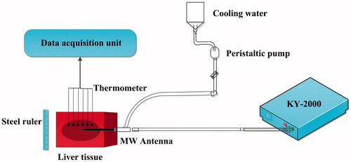
To verify the accuracy of FEM models, 20 sets of ex vivo pig liver experiments were conducted under the same conditions. The experimental setup included a cooled-shaft microwave unit of 2450-MHz (KY-2000; Kangyou Microwave Energy Sources Institute, Nanjing, China), a peristaltic pump (BTDI-100; Baoding Longer Precision Pump, Inc, Hebei, China), thermometers (YWY-2; Kangyou Microwave Energy Sources Institute, Nanjing, China), a steel ruler, and ex vivo pig livers (). This study used MWA power settings of 40, 45, 50, 55, and 60 W. The positions of the thermometers were disposed at V1 (10 mm, −5 mm), V2 (10 mm, −15 mm), V3 (10 mm, 0 mm), V4 (20 mm, 5 mm), V5 (25 mm, 5 mm), and V6 (10 mm, 10 mm). These thermometers were used to measure the temperature changes to validate the temperature prediction accuracy of the FEM models. In addition, a steel ruler was used to measure the size of thermal coagulation zones after MWA.
Figure 1. MWA experimental setup for validation.
2.3. Characterization of IS-54 evolution
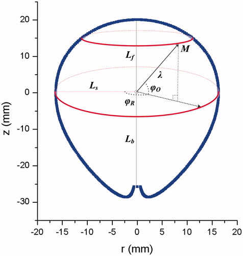
In previous studies, IS-54 on the r-z plane was often expressed by characteristic lengths, whose growing functions with time take logarithmic forms [Citation20]. These characteristic lengths generally include the long-axis and short-axis diameters of thermal coagulation zones. The ablated zone was sectioned along the antenna shaft, and the diameter of the zone along the antenna insertion axis was measured as the long-axis diameter. The short-axis diameter was orientated perpendicular to the long-axis diameter. According to the water-cooled properties of this MW antenna, the forward long-axis length backward long-axis length
and short-axis radius
are taken as the characteristic lengths
() to more accurately characterize the change of coagulation zone size. Previous experiments have demonstrated that
can be represented by power functions (similar to logarithmic forms), as illustrated in EquationEquation (10)
(10)
(10) :
(10)
(10)
where
are the coefficients of the characteristic length growth models.
Figure 2. The schematic view of characteristic lengths. is the forward long-axis length,
is the backward long-axis length,
is the short-axis radius,
is the rotation polar-angle,
is the offset polar-angle, and
is the polar radius. The origin is disposed at the MW emission point. The blue line indicates the thermal coagulation zone.
The changing size of the thermal coagulation zones over time was obtained from the FEM models and was then fitted by 1stOpt (7 D-Soft High Technology, Inc., Beijing, China), which is a mathematical optimization analysis toolbox. The Levenberg-Marquardt (LM) optimization algorithm was used to fit functions. Because the growth patterns of thermal coagulation zones in the initial MWA stage were irregular, this study predominantly analyzed the growth model after 100 s of ablation. Based on the properties of the MW antenna, the forward IS-54 and the backward IS-54 were separately modeled using the selected characteristic lengths [Citation21]:
(11)
(11)
(12)
(12)
where
and
are the coefficients of the forward IS-54 and the backward IS-54, respectively;
and
are the forward shape variation factor and the backward shape variation factor, respectively. These shape variation factors are used to deal with the minor variability of IS-54 shapes over time and also take the form of power functions:
(13)
(13)
(14)
(14)
where
and
are the coefficients of the shape variation factors.
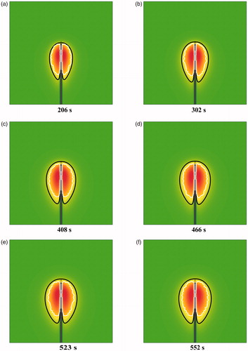
Based on the FEM data at some discrete time (100 s, 150 s, 200 s, etc), the IS-54 models were precisely obtained from EquationEquations (10)–(14). Then, to validate the effectiveness and applicability of this modeling method, the derived IS-54 models were compared with the FEM data at some other time (206 s, 302 s, 408 s, 466 s, 523 s, and 552 s).
2.4. Conformal coverage algorithm for treating physical liver tumors
Any point, M, on the 3-D thermal coagulation zone models or physical liver tumors can be characterized by a polar presentation: polar radius rotation polar-angle
[0, 2π], and offset polar-angle
[-π/2, π/2], as shown in . Conformal coverage of liver tumors by IS-54 can be achieved by comparing the corresponding polar radii in the case of
alignment and
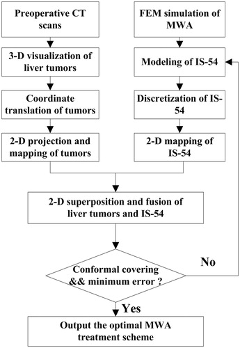
alignment. As such, a novel conformal coverage algorithm based on bipolar-angle mapping is proposed in this study ().
Figure 3. Work flowchart of the conformal coverage algorithm.
2.4.1. 2-D Projection and mapping of physical liver tumors
Preoperative CT slices of liver tumors after manual segmentation were loaded to form 3-D volume data. Then, 3-D surface reconstructions of ROI (region of interests) were conducted using the MC algorithm. The surface rendering results of liver tumors were quantified to derive the length of the tumor maximum diameter (), the coordinate of the tumor gravity center (
), and the orientation vector of the maximum diameter through the gravity center (
), where
indicates the tumor’s size,
is the insertion position of the MW antenna [Citation22], and
represents the insertion direction of the MW antenna. If the 3-D surface result of the tumor was composed of
points (
), then
and
were computed as follows:
(15)
(15)
(16)
(16)
(17)
(17)
where
represents the index of the tumor points, and point
is the endpoint of the maximum diameter through the gravity center.
To ensure that the gravity center of the tumor was located at the origin (i.e. the microwave emission point), coordinate translation was performed as follows:
(18)
(18)
To reduce the computational loads, 3-D coordinates of the tumor were projected into 2-D coordinates
on the r-z plane, as illustrated in EquationEquation (19)
(19)
(19) :
(19)
(19)
Because the maximum diameter was required to align with the insertion direction of the MW antenna, coordinate rotation of the tumor was performed according to EquationEquation (20)(20)
(20) :
(20)
(20)
where
is the intersection angle between the maximum diameter and the z axis.
After coordinate transformation of the tumor surface data, the polar radius was mapped based on bipolar-angles
and
(EquationEquation (21)
(21)
(21) ), where
[0, 2π] was designated as the horizontal axis and
[-π/2, π/2] was designated as the vertical axis.
(21)
(21)
2-D projection and mapping of physical liver tumors was then achieved through the above process.
2.4.2. Bipolar-angle mapping of IS-54
IS-54 models for 40, 45, 50, 55, and 60 W power levels were built according to EquationEquations (10)–(14). The offset angle [-π/2, π/2] of IS-54 was discretized into 1800 equal parts in order to align with discrete values of 3-D tumor surface results. However, discretization of
was not required due to the rotational symmetry of IS-54. 2-D bipolar-angle mapping of IS-54 models was achieved based on
and
where the corresponding polar radius
was represented by color brightness. The color brightness was enhanced with increasing
2.4.3. Superposition and fusion of liver tumors and IS-54
2-D projection views of the liver tumors and IS-54 on the r-z plane were superimposed and their bipolar-angle maps were fused together in order to intuitively learn the conformal coverage conditions of the liver tumors.
2.4.4. Conformal coverage of liver tumors by IS-54
IS-54 gradually grows with MWA duration. As shown in , when the minimum difference of corresponding polar radii was equal to only 5 mm (this value could be changed based on the specific safety margin requirement, which was set to 5 mm in this study), conformal coverage was accomplished; i.e., the safety margin was guaranteed and the optimal ablation time was obtained. Therefore, the objective function was defined as follows:
(22)
(22)
Figure 4. Conformal coverage illustration of liver tumor by IS-54. The blue dots indicate the mesh nodes of the tumor surface. is the forward long-axis length,
is the backward long-axis length,
is the short-axis radius,
is the offset polar-angle,
represents the polar radius of IS-54, and
represents the polar radius of the tumor surface model. The origin is set at the MW emission point.
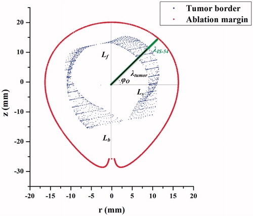
When the objective function was satisfied, the corresponding lost function was computed. The lost function was defined as the standard deviation (SD) between the ablative margin (AM) and the tumor surface:
(23)
(23)
By changing power levels, the corresponding SD was computed. The suitable MWA parameters (ablation power, ablation duration) were output based on the minimum SD. In addition, the gravity center of the tumor was designated as the insertion position of the MW antenna and the orientation vector of the maximum diameter through the gravity center (
) determined the insertion orientation of the MW antenna. According to this algorithm, optimal MWA treatment schemes could be determined.
3. Results
3.1. 3-D Reconstruction results of liver tumors
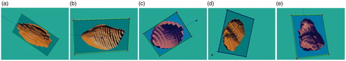
In order to test the applicability of the conformal coverage algorithm, 15 liver tumors with different shapes and different sizes were obtained and reconstructed, as shown in . The 3-D surface data as STL files were quantitatively analyzed using the VC++ 6.0 platform to output the gravity center coordinates, the maximum diameter lengths, and the maximum diameter vectors through the gravity centers of these tumors, where the upper-left corner of the first CT slice was designated as the origin.
Figure 5. Surface reconstruction results of liver tumors.
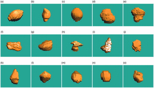
The maximal diameter of these tumors ranged from 12.329 mm to 78.612 mm (mean ± SD, 39.094 ± 19.447 mm). The detailed data of these surface results are listed in . Based on this detailed information, the physical tumors were precisely characterized.
Table 1. Detailed data of tumor reconstruction results.
3.2. FEM simulation results and experimental verification
Twenty sets of experiments were conducted on ex vivo porcine livers under 40, 45, 50, 55, and 60 W power levels, respectively. The FEM simulation results of MWA temperature distributions and coagulation zones were then validated using these experimental data.
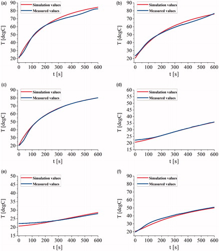
shows the temperature comparison plots of the measurements and the simulations at several verification points. The average of the maximum errors, the average errors, and the average standard deviations between simulation temperatures and measurements at V1, V2, V3, V4, V5, and V6 were 2.879 °C, 1.126 °C, and 0.836 °C, respectively.
Figure 6. The temperature comparison plots of the measurements and the simulations at (a) the point V1, (b) the point V2, (c) the point V3, (d) the point V4, (e) the point V5, and (f) the point V6.
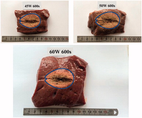
According to gross pathologic examination, the ablation zones included a central “white coagulation zone” surrounded by a “red hemorrhagic zone” [Citation23]. The white coagulation zone was generally accepted to represent coagulated tissue and was consistent with irreversible cell death [Citation24]. The characteristic lengths were measured to validate the simulation size of the thermal coagulation zones. The errors between the measurements and the simulation data were within ±5%. The comparison of characteristic lengths for the coagulation zones demonstrates that the FEM models can accurately simulate the actual ablation effects of ex vivo porcine livers and effectively indicate the changes of thermal coagulation zones. shows some sectional images of porcine livers after 600 s of MWA at 45, 50, and 60 W power levels, where the blue line represents IS-54 obtained from FEM models. It is clear that FEM data can effectively reflect the changes of thermal coagulation zones. Therefore, this study successfully derived the characterization functions of IS-54 over time based on FEM models.
Figure 7. The sectional images of porcine livers after 600 s at 45, 50, and 60 W power levels. IS-54 indicated by the blue line was overlain onto the pathology images of the ablated livers.
3.3. Characterization of IS-54 evolution
According to FEM model data and the function forms of IS-54 (EquationEquations (10)–(14)), the corresponding coefficients of IS-54 models were fitted by 1stOpt, as summarized in and . It was demonstrated in this study that the shape variation characteristics of IS-54 at 40, 45, 50, 55, and 60 W were extremely similar. Therefore, and
for different power levels employed the same power function forms. The expressions of
and
were fitted by 1stOpt, as shown by EquationEquations (24)
(24)
(24) and Equation(25)
(25)
(25) :
(24)
(24)
(25)
(25)
Table 2. Characteristic length growth models at various ablation powers.
Table 3. Corresponding coefficients of IS-54.
Therefore, the precise mathematical functions of IS-54 curves could be obtained, where thermal coagulation zone sizes were determined by the characteristic length growth models and the shape changes of these zones were dependent on the shape variation factors.
The shapes and sizes of IS-54 simulation isotherms and the prediction curves were generally in good agreement. At 206 s, 302 s, 408 s, 466 s, 523 s, and 552 s, the standard deviations between the simulations and the predictions were 0.777 mm, 0.772 mm, 0.799 mm, 0.817 mm, 0.818 mm, and 0.881 mm, respectively. Furthermore, the paired student t-test in SPSS (SPSS Inc., Chicago, USA) was used to identify differences between these results, and the p values were .0835, .670, .635, .894, .110, and .725, respectively. All p values were greater than .05, so there was no statistically significant difference. In summary, these IS-54 characterization functions were able to perfectly predict changes in the thermal coagulation zones over time. 3 D thermal coagulation zone models were then obtained based on the rotation operation of IS-54.
3.4. Determining liver tumor treatment schemes using the conformal coverage algorithm
Selection of the treatment scheme in tumor MWA depends on correct localization of the MW antenna and suitable energy applications by KY-2000. The insertion position and direction of the MW antenna is determined by the gravity center of the liver tumor and the orientation vector of the maximum diameter through the gravity center, respectively. The energy applications rely on ablation power and ablation duration.
3.4.1. R-z projection results of physical liver tumors
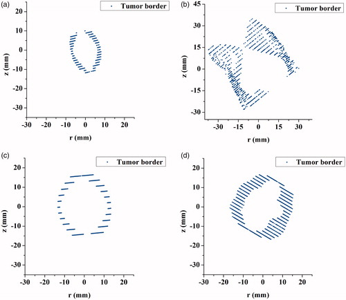
According to EquationEquations (18)–(20), the surface reconstruction results of liver tumors were processed to achieve the r-z projection, coordinate translation, and coordinate rotation operations. illustrates r-z projection views for cases 1–4, in which the gravity centers of the tumors have been translated to the origin and the maximum diameters through the gravity centers of the liver tumors are aligned with the insertion direction of the MW antenna. The projection results of physical liver tumors were then overlain on r-z plan views of IS-54, as shown in . Through the combined 2-D image, we qualitatively observed whether IS-54 completely covered the original tumor for each tumor node in all directions.
Figure 8. R-z projection views of liver tumors. The blue dots indicate the mesh nodes of the tumor surfaces. The gravity centers of the tumors have been placed at the origin.
3.4.2. Mapping results of liver tumors and IS-54
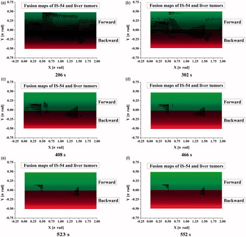
In order to accurately quantify the conformal coverage conditions of liver tumors, 2-D mapping of tumor surface results and IS-54 were performed based on bipolar-angles and
as shown in , where the red regions represent the backward color maps of IS-54, the green regions represent the forward color maps of IS-54, and the color brightness reflects the lengths of polar radii of IS-54. The color brightness of these maps increased over time due to the increasing polar radii of IS-54. The maximum brightness in forward and backward IS-54 were close to
of π/2 and -π/2, respectively. On the condition of bipolar-angle alignment of IS-54 and liver tumors, the tumor nodes protruding from the IS-54 safety margin are displayed as black dots on the IS-54 maps. As such, tumor maps and IS-54 maps (using case 4 under 60 W as an example) were fused together. IS-54 gradually evolved and increased with time, so the black dots on the fusion maps gradually decreased in number.
Figure 9. Fusion maps of IS-54 and liver tumors. The red regions represent the backward color maps of IS-54, and the green regions represent the forward color maps of IS-54. The black dots indicate the tumor nodes protruding from IS-54 safety margin.
3.4.3. Treatment schemes based on the conformal coverage algorithm
As shown in , when the black dots on the fusion maps completely disappeared, conformal coverage was accomplished. At different heating powers, reasonable ablation parameters of liver tumors were derived based on EquationEquation (22)(22)
(22) and the SD of errors were calculated based on EquationEquation (23)
(23)
(23) . Finally, the optimal treatment schemes of liver tumors were output according to the minimum SD.
Figure 10. MWA planning interface based on conformal coverage algorithm. The upper-left part of the figure shows the plan projection view of the tumor model and IS-54, the upper-right part shows the fusion map of the tumor model and IS-54, the lower-left part is the selection module of thermal ablation modes and the input module of liver tumor models, and the lower-right part is the output module of optimal treatment parameters.
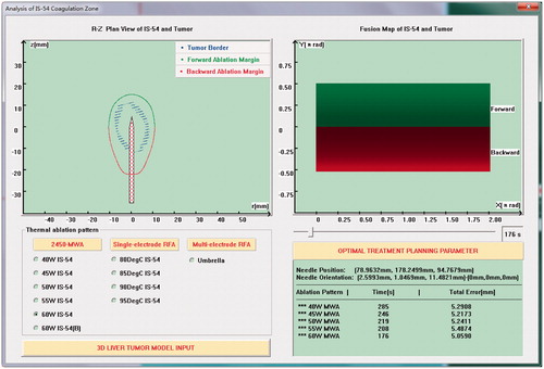
Because KY-2000 is suitable for the treatment of single tumors within 50 mm, some tumors in this study could not be treated by the ablator and hence the corresponding ablation parameters were not calculated. The specific ablation parameters of cases 1–15 are shown in .
Table 4. Ablation parameters of liver tumors.
In addition, details of the insertion position and direction of the MW antenna are listed in . The cross-sectional views of cases 1–5 are illustrated in , which indicate that the MWA antenna was inserted to the gravity center positions and was aligned with the maximum diameters through the gravity centers.
Figure 11. The cross-sectional views of liver tumors and MW antenna. The blue lines indicate the insertion positions and orientations of the MW antenna.
4. Discussion
For thermal ablation treatments, patients with a safety margin of greater than 5 mm have a lower probability of developing LTP [Citation25]. For a highly precise estimate, specific IS-54 models of ex vivo porcine livers were established in this study and CT images of patients were used to derive quantitative data of tumors. 2-D projection images and fusion maps of physical tumors and IS-54 were then obtained. Projection images enabled a qualitative comparison to assist in determining the approximate ablation duration and reducing the computational loads. Fusion maps provided a quantitative comparison of physical tumors and IS-54. The major contribution of this study is the new conformal coverage method based on these fusion maps that can determine the treatment parameters in real time and enhance the effectiveness of clinical MWA. Moreover, point-to-point rigid registration of tumor data and IS-54 is not necessary.
An advantage of this bipolar-angle mapping method is that it can achieve conformal ablations of all tumors. In previous studies using combined 3-D images of physical tumors and ablation zones [Citation25,Citation26], not all cases could achieve a 5-mm safety margin. Some conformal coverage methods have been proposed based on comparisons of specific lengths [Citation27,Citation28]; thus, the precision requires improvement. The largest 3-D sphere fitting thermal coagulation zone has often been used for planning purposes [Citation29]. Moreover, some tumor maps have been derived to achieve parameterization of the tumor surface, including spherical map [Citation30] and cylindrical map [Citation22]. To reduce the high computational load, a tumor pseudo-cylindrical map has been proposed for reliable therapy assessment and as an interactive navigation tool; however, this map is not suitable for concave tumors and deskewing is compulsory [Citation22].
Based on the proposed conformal coverage algorithm, it is easy to obtain the optimal MWA treatment parameters when the maximum diameters of the liver tumors are much smaller than the treatment limit of KY-2000 (<50 mm); for example, the 1st, 13th and 14th liver tumors shown in . However, if the size of the liver tumor is close to 50 mm, then conformal treatment is difficult to achieve. This is due to the considerations of the 5-mm safety margin and the specific morphology of the liver tumors (e.g. the 5th, 6th, 9th and 15th cases). When the size of the liver tumors is larger than 50 mm, the effective treatment parameters cannot be obtained (e.g. the 2nd, 7th and 10th cases). In addition, if the shapes of the liver tumors are similar to that of IS-54 (a pear-like shape), there are smaller ablation errors; i.e. less damage to normal tissue (e.g. the 1st, 3rd, and 13th cases). For some irregular and larger tumors, MWA conformal treatments can be achieved by applying higher powers [Citation31], infusing saline into the tissue surrounding the MW antenna [Citation32], or using multiple applicators [Citation33] to increase the ablation zone sizes.
In this study, the coagulation zone sizes were measured solely on the 54 °C isotherm, because the isotherm could be simply and quickly derived. In order to verify the validity of the temperature threshold method, IS-54 was compared with existing coagulation zone models based on thermal equivalent doses, including the Arrhenius model and CEM43 model [Citation34–36].
The Arrhenius model is the most widely used method for evaluating thermal coagulation zones, which is given as follows:
(26)
(26)
(27)
(27)
where
is the tissue death fraction (%),
is the tissue death index,
is time (s),
is the frequency factor (s−1),
is the activation energy for the irreversible coagulation reaction (J/mol),
is the universal gas constant (8.314 J/mol/K), and
is the absolute temperature (K). For healthy liver tissue,
s−1,
J/mol/K [Citation37]. When
(i.e.
), the biological tissue is considered to have undergone complete thermal coagulation.
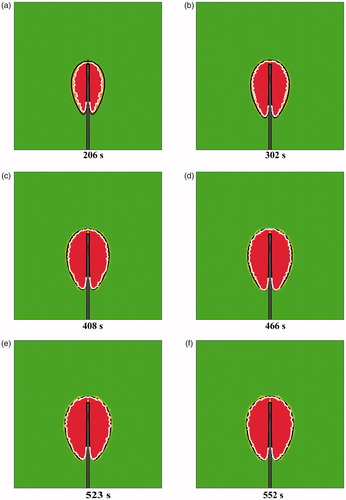
shows a comparison between the IS-54 model and the Arrhenius thermal damage model for different MW durations. The red region represents the thermal coagulation zone, the black line represents the IS-54 model and the white line represents the Arrhenius thermal damage model. The Arrhenius thermal damage model has a non-smooth outline and is slightly smaller than IS-54. However, with time, the Arrhenius thermal damage model becomes approximately the same as IS-54; thus, the shape and size changes of the Arrhenius thermal damage model are similar to those of IS-54 for different MWA durations. Therefore, the modeling method of IS-54 is also suitable for the Arrhenius thermal damage model. This further verifies the effectiveness of the proposed method.
Figure 12. A comparison between the IS-54 and the Arrhenius thermal damage model at (a) 206 s, (b) 302 s, (c) 408 s, (d) 466 s, (e) 523 s, and (f) 552 s. The red region represents the thermal coagulation zone, the black line represents the IS-54 model, and the white line represents the Arrhenius model.
It is hypothesized that the CEM43 model is effective for the in vivo MWA condition. To this end, IS-54 was compared with the CEM43 model, which is defined as:
(28)
(28)
where CEM43 is the cumulative equivalent minutes at 43 °C (min);
is a dimensionless factor, and is set to 0.25 and 0.5 for temperatures below and above 43 °C, respectively;
is time (s); and
is temperature (°C).
The lethal thermal dose threshold for livers is 240 CEM43; i.e., CEM43=240 min [Citation38]. compares the IS-54 model and the 240 CEM43 thermal damage model under different MWA durations. The aurantius region represents the thermal coagulation zone, the black line represents the IS-54 model, and the white line represents the 240 CEM43 thermal damage model. IS-54 is significantly larger than the 240 CEM43 thermal damage model, which is attributable to the fact that actual blood perfusion of liver is not considered in the FEM simulation models. Therefore, in future work, the IS-54 model based on FEM simulation data of in vivo livers should be further derived for an effective comparison with the 240 CEM43 model. Despite this, the 240 CEM43 thermal damage model also exhibits time-evolution characteristics. Therefore, in the evaluation of the 240 CEM43 thermal damage model, the characteristic length growth model and the shape variation factor can also be used to characterize the shape and size changes of the thermal coagulation zones, although the modeling forms may be different from IS-54. In addition, compared with the 240 CEM43 thermal damage model, the IS-54 model is relatively simple and requires a significantly shorter calculation time. Hence, the IS-54 model was employed in the proposed conformal coverage algorithm.
Figure 13. A comparison between the IS-54 and the 240 CEM43 thermal damage model at (a) 206 s, (b) 302 s, (c) 408 s, (d) 466 s, (e) 523 s, and (f) 552 s. The aurantius region represents the thermal coagulation zone, the black line represents the IS-54 model, and the white line represents the 240 CEM43 model.
This study only considered the homogeneous tissue model instead of healthy and tumorous tissue models, which enables a direct comparison with existing experimental studies. If the tumor is located very near to the liver boundary or the blood vessel, a geometrically-accurate surface model of the liver or blood vessel should be reconstructed and truncated around the tumor to reduce the high computational demand [Citation39]. The geometrically-truncated model can then be mapped on the bipolar-angle map of the tumor and IS-54. In order to ensure the liver boundary or the blood vessel is not ablated, the polar radius of IS-54 must be less than the corresponding polar radius of the liver boundary or blood vessel. As such, the liver capsule and the blood vessel will not be destroyed according to the proposed conformal coverage algorithm.
Nevertheless, this study has several limitations. Firstly, post-interventional CT images are not acquired and, therefore, a comparison to post-interventional data cannot be performed. Secondly, the physical constraints of antenna insertion are not considered [Citation40–42]. Thirdly, the characterization models of IS-54 were derived based on ex vivo porcine livers and the proposed correlation might change if there is a large blood vessel in close proximity to the target. Heat sinks caused by large blood vessels during treatment would lead to incomplete thermal coagulation [Citation43,Citation44]. In future work, an FEM simulation model including large vessels can be established to derive the growth models of specific characteristic lengths (e.g. the distance from the MW antenna to large vessels) and the functional expressions of thermal coagulation zones. In addition, tumor deformation during microwave ablation was not considered, which is another limitation of this study. The IS-54 model would, therefore, overestimate the actual treated tissue and the safety margin would be larger than the fixed 5 mm due to tissue contraction [Citation45,Citation46]. However, the tissue contraction during MWA could be evaluated using CT images [Citation47] or measured using small specimens of ex vivo liver [Citation48]. The precise evaluation results were then employed to amend the characteristic length growth models and shape variation factors of IS-54. In addition, by changing the objective function (EquationEquation (22)(22)
(22) ), the proposed conformal coverage method can be extended to cover different conditions, not a fixed 5 mm pretreatment margin.
5. Conclusion
This study presents a conformal coverage method for liver tumors during MWA. Using 2-D bipolar-angle mapping of IS-54 models and tumor surface data, MWA treatment schemes can be quickly and precisely formulated. Therefore, the proposed method can be applied to computer-assisted MWA treatment planning of liver tumors. In future study, in vivo properties of tumor tissues will be considered to obtain more accurate MWA treatment parameters. Furthermore, the effectiveness of this conformal coverage method should be validated through a comparison with clinical MWA results of liver tumors.
Acknowledgements
The authors would like to thank the anonymous reviewers for their constructive comments and suggestions.
Disclosure statement
The authors declare that they have no conflict of interest.
Additional information
Funding
References
- Meloni MF, Chiang J, Laeseke PF, et al. Microwave ablation in primary and secondary liver tumours: technical and clinical approaches. Int J Hyperthermia. 2017;33:15–24.
- De Cobelli F, Marra P, Ratti F, et al. Microwave ablation of liver malignancies: comparison of effects and early outcomes of percutaneous and intraoperative approaches with different liver conditions: new advances in interventional oncology: state of the art. Med Oncol. 2017;34:34–49.
- Wu X, Liu BL, Xu BK. Theoretical evaluation of high frequency microwave ablation applied in cancer therapy. Appl Therm Eng. 2016;107:501–507.
- Leung U, Kuk D, D'Angelica MI, et al. Long-term outcomes following microwave ablation for liver malignancies. Br J Surg. 2015;102:85–91.
- Ahmed M, Brace CL, Lee FT, et al. Principles of and advances in percutaneous ablation. Radiology. 2011;258:351–369.
- Brace CL. Radiofrequency and microwave ablation of the liver, lung, kidney, and bone: what are the differences? Curr Probl Diagn Radiol. 2009;38:135–143.
- Park WKC, Maxwell AWP, Frank VE, et al. Evaluation of a novel thermal accelerant for augmentation of microwave energy during image-guided tumor ablation. Theranostics. 2017;7:1026–1035.
- Deshazer G, Prakash P, Merck D, et al. Experimental measurement of microwave ablation heating pattern and comparison to computer simulations. Int J Hyperthermia. 2017;33:74–82.
- Liang P, Dong BW, Yu XL, et al. Computer-aided dynamic simulation of microwave-induced thermal distribution in coagulation of liver cancer. IEEE Trans Biomed Eng. 2001;48:821–829.
- Sun YY, Cheng ZG, Dong L, et al. Comparison of temperature curve and ablation zone between 915- and 2450-MHz cooled-shaft microwave antenna: results in ex vivo porcine livers. Eur J Radiol. 2012;81:553–557.
- Lopresto V, Pinto R, Farina L, et al. Microwave thermal ablation: effects of tissue properties variations on predictive models for treatment planning. Med Eng Phys. 2017;46:63–70.
- Zhang SY, Shang SQ, Han YQ, et al. Ex vivo and in vivo monitoring and characterization of thermal lesions by high-intensity focused ultrasound and microwave ablation using ultrasonic nakagami imaging. IEEE Trans Med Imaging. 2018; 37:1701–1710.
- Goldberg SN, Gazelle GS, Mueller PR. Thermal ablation therapy for focal malignancy: a unified approach to underlying principles, techniques, and diagnostic imaging guidance. Am J Roentgenol. 2000;174:323–331.
- Dodd GII, Soulen MC, Kane RA, et al. Minimally invasive treatment of malignant hepatic tumors: at the threshold of a major breakthrough. RadioGraphics. 2000;20:9–27.
- Lopresto V, Pinto R, Farina L, et al. Treatment planning in Microwave Thermal Ablation: clinical gaps and recent research advances. Int J Hyperthermia. 2017; 33:83–100.
- Lu XS, Xie QL, Zha YF, et al. Fully automatic liver segmentation combining multi-dimensional graph cut with shape information in 3D CT images. Sci Rep-UK. 2018;8:10700.
- Chiang J, Wang P, Brace CL. Computational modelling of microwave tumour ablations. Int J Hyperthermia. 2013;29:308–317.
- Pennes HH. Analysis of tissue and arterial blood temperatures in the resting humanforearm. J Appl Phys. 1948;1:93–122.
- Gao HJ, Wang XR, Wu SC, et al. 2450-MHz microwave ablation temperature simulation using temperature-dependence feedback of characteristic parameters. Int J RF Microw Comput Aided Eng. 2019;29:e21488.
- Hoffmann R, Rempp H, Erhard L, et al. Comparison of four microwave ablation devices: an experimental study in ex vivo bovine liver. Radiology. 2013;268:89–97.
- Gao HJ, Wang XR, Wu SC, et al. Characterization of 2450-MHz microwave thermal coagulation zone based on characteristic length growth model and shape variation factor. Int J RF Microw Comput Aided Eng. 2019;29:e21705.
- Rieder C, Weihusen A, Schumann C, et al. Visual support for interactive post-interventional assessment of radiofrequency ablation therapy. Comput Graph Forum. 2010;29:1093–1102.
- Ahmed M, Solbiati L, Brace CL, et al. Image-guided tumor ablation: standardization of terminology and reporting criteria - A 10-year update. J Vasc Interv Radiol. 2014;25:1691–1705.
- Wang Y, Sun YY, Feng L, et al. Internally cooled antenna for microwave ablation: results in ex vivo and in vivo porcine livers. Eur J Radiol. 2008;67:357–361.
- Jiang CL, Liu BX, Chen SL, et al. Safety margin after radiofrequency ablation of hepatocellular carcinoma: precise assessment with a three-dimensional reconstruction technique using CT imaging. Int J Hyperthermia. 2018;34:1135–1141.
- Kim YS, Lee WJ, Rhim H, et al. The minimal ablative margin of radiofrequency ablation of hepatocellular carcinoma (>2 and <5 cm) needed to prevent local tumor progression: 3D quantitative assessment using CT image fusion. Am J Roentgenol. 2010;195:758–765.
- Gao HJ, Yang CL, Zhao L, et al. Design and implementation of liver hyperthermia treatment planning system. J Beijing Univ Technol. 2010;25,4:17–20.
- Ai HM, Wu SC, Gao HJ, et al. Optimization algorithm for hepatic tumor microwave ablation. International Conference on Biomedical Engineering and Biotechnology, Macao, China, May 28–30, 2012, pp. 860–863.
- Bangard C, Wiemker R, Rösgen S, et al. Optimal visualization and 3D-asphericity quantification for postoperative result assessment of hepatic radiofrequency ablations. J Comput Ass Rad Surg. 2009;4:59–70.
- Shen L, Makedon F. Spherical Parameterization for 3D Surface Analysis in Volumetric Images. International Conference on Information Technology: Coding and Computing, Las Vegas, NV, USA, April 5–7, 2004, pp. 643–649.
- Goldberg SN. Radiofrequency tumor ablation: principles and techniques. Eur J Ultrasound. 2001;13:129–147.
- Haemmerich D, Tungjitkusolmun S, Staelin ST, et al. Finite-element analysis of hepatic multiple probe radio-frequency ablation. IEEE Trans Biomed Eng. 2002;49:836–842.
- Hall SK, Ooi EH, Payne SJ. A mathematical framework for minimally invasive tumor ablation therapies. Crit Rev Biomed Eng. 2014;42:383–417.
- Reddy G, Dreher MR, Rossmann C, et al. Cytotoxicity of hepatocellular carcinoma cells to hyperthermic and ablative temperature exposures: in vitro studies and mathematical modelling. Int J Hyperthermia. 2013;29:318–323.
- Zhang B, Moser MAJ, Zhang EM, et al. A review of radiofrequency ablation: large target tissue necrosis and mathematical modelling. Phys Medica. 2016;32:961–971.
- Diederich CJ. Thermal ablation and high-temperature thermal therapy: overview of technology and clinical implementation. Int J Hyperthermia. 2005;21:745–753.
- Singh S, Repaka R. Numerical study to establish relationship between coagulation volume and target tip temperature during temperature-controlled radiofrequency ablation. Electromagn Biol Med. 2018;37:13–22.
- Seror O, Lepetit-Coiffe M, Le Bail B, et al. Real time monitoring of radiofrequency ablation based on MR thermometry and thermal dose in the pig liver in vivo. Eur Radiol. 2008;18:408–416.
- Ooi EH, Lee KW, Yap S, et al. The effects of electrical and thermal boundary condition on the simulation of radiofrequency ablation of liver cancer for tumours located near to the liver boundary. Comput Biol Med. 2019;106:12–23.
- Zhai W, Xu J, Zhao Y, et al. Preoperative surgery planning for percutaneous hepatic microwave ablation. International Conference on Medical Image Computing and Computer-Assisted Intervention, New York, NY, USA, September 6–10, 2008, pp. 569–577.
- Seitel A, Engel M, Sommer CM, et al. Computer-assisted trajectory planning for percutaneous needle insertions. Med Phys. 2011;38:3246–3259.
- Liu P, Qin J, Duan B, et al. Overlapping radiofrequency ablation planning and robot-assisted needle insertion for large liver tumors. Int J Med Robotics Comput Assist Surg. 2019;15:e1952.
- Narayanan G, Froud T, Suthar R, et al. Irreversible electroporation of hepatic malignancy. Semin Interv Radiol. 2013;30:67–73.
- Serra C, Cucchetti A, Felicani C, et al. Assessment of radiofrequency ablation efficacy for hepatocellular carcinoma by histology and pretransplant radiology. Liver Transpl. 2019;25:88–97.
- Liu D, Brace CL. Numerical simulation of microwave ablation incorporating tissue contraction based on thermal dose. Phys Med Biol. 2017;62:2070–2086.
- Park CS, Liu C, Hall SK, et al. A thermoelastic deformation model of tissue contraction during thermal ablation. Int J Hyperthermia. 2018;34:221–228.
- Brace CL, Gagnon D, Borden Z, et al. Ablation-induced tissue contraction measured by CT: correlation with dehydration. World Conference on Interventional Oncology, New York, NY, USA, June 9–11, 2011.
- Farina L, Weiss N, Nissenbaum Y, et al. Characterisation of tissue shrinkage during microwave thermal ablation. Int J Hyperthermia. 2014;30:419–428.