
 ?Mathematical formulae have been encoded as MathML and are displayed in this HTML version using MathJax in order to improve their display. Uncheck the box to turn MathJax off. This feature requires Javascript. Click on a formula to zoom.
Abstract
Introduction: Irreversible electroporation (IRE) combined with a catheter-based electrode during endoscopy is a potential alternative treatment method for digestive tract tumors. The aim of this study was to investigate the electrical injury (EI) and thermal injury (TI) to the digestive tract via numerical analyses and to evaluate the role and impact of electrode configurations and pulse settings on the efficacy and outcomes of IRE.
Materials and methods: A finite element method was used to solve the numerical model. A digestive tract model having 4-mm-thick walls and two catheter-based electrode configuration models were constructed. The distributions of electric fields, temperature, electrical conductivity, tissue injury and limitation on the pulse number required for IRE were calculated and compared.
Results: Electrode length is an important geometric parameter for electrodes in the monopolar model (MPM), while electrode spacing affects the outcomes in the bipolar model (BPM). Increasing the pulse voltage reduces the pulse number required for tissue ablation, while increasing the risk of TI. In total, there were 6 NT-IRE protocols, 12 thermal-IRE protocols and 30 TI protocols. All of the NT-IRE protocols were set in BPMs with a voltage of 0.50 kV. With increasing electrode spacing, the minimum pulse number decreased. However, thermal effects were inevitable in the MPM.
Conclusions: The electrode configuration and pulse settings are adjusted to achieve NT-IRE synergistically. The BPM is more reliable for achieving NT-IRE in 4-mm-thick digestive wall. Future in vitro and in vivo studies are needed to support and validate this conclusion.
Introduction
Irreversible electroporation (IRE) is an emerging focal ablation technique based on the biological effects of microsecond-pulsed electrical fields [Citation1–3]. Although the underlying mechanism of cell death during IRE is not yet completely understood, there is general agreement that the balance of the transmembrane potential has been disrupted during IRE and thereby causing apoptosis or necrosis as a result [Citation4–6]. Depending on the specific effect on cell membrane, IRE is capable of producing lesions without thermal injury (TI) [Citation7]; thus, it preserves other tissue components such as macromolecules, connective tissue and tissue scaffold [Citation8]. Therefore, IRE is completely different from thermal-based techniques such as radiofrequency ablation (RFA) and microwave ablation [Citation5,Citation9]. Thus far, IRE has been approved for clinical use as a focal therapy for liver, pancreatic and prostate cancers [Citation10,Citation11].
Generally, RFA is not suitable for treatment of the gastrointestinal wall, bile duct, pancreatic duct or tumors adjacent to large blood vessels [Citation6,Citation12]. The most notable reason for this is that complete ablation by penetrative delivery of thermal energy can disrupt structural integrity, leading to perforation or bleeding, while conservative energy delivery lowers the efficacy of ablation. Moreover, the efficacy of thermal-based ablation will be affected by the heat-sink effect of blood flow from the adjacent large vessels. Therefore, IRE is suitable for sites that have contraindications for thermal-based treatment techniques [Citation13].
A needle-shaped electrode array that punctures the tissue surrounding the tumor is generally employed for IRE in clinical practice [Citation14]. However, needle-like electrodes are not suitable for hollow organs. Instead, a catheter-based electrode is suitable for preventing perforation or injury. Srimathveeravalli et al. reported the safety and efficacy of full-thickness ablation in the porcine rectum and urinary tract by intraluminal catheter-based IRE [Citation13,Citation15]. Ueshima et al. [Citation16] showed that transmural ablation of the normal porcine common bile duct was feasible without affecting the duct patency via catheter-based IRE under endoscopy. Ren et al. [Citation17] evaluated the safety and efficacy of IRE with a catheter-based electrode for gastric tissue ablation in rabbits. Consequently, IRE combined with a catheter-based electrode under endoscopy is a potential alternative method for minimally invasive treatment of digestive cancers or undesired tissues.
The geometric parameters and configuration of the electrodes are closely related to the outcomes of IRE [Citation18,Citation19]. Currently, there are no commercially available catheter-based electrodes for IRE in clinical practice. The electrodes used in animal studies were based on or modified from RFA catheters [Citation16,Citation20,Citation21]. Although experimental studies have demonstrated the safety and efficacy of these electrodes, the relationship between the electrode configuration and ablation zone remains undetermined. In addition, the outcome of IRE is also associated with pulse settings including pulse duration, total number of pulses, frequency and voltage [Citation5]. Notably, for an ideal treatment, it is of utmost importance to cover the entire target tumor with sufficient pulse energy and to reduce unnecessary injury to the surrounding normal tissue [Citation22,Citation23]. However, the pulse settings in previous catheter-based IRE are often set empirically or based on prior studies, which may cause unnecessary injury.
Numerical analysis is a useful and common method of investigating the electrode configuration and pulse settings in IRE [Citation1]. Generally, a numerical study for IRE should include both electrical and thermal analyses. High-voltage electric pulses constitute the energy source used to create an ablation lesion during IRE, which can be treated as an irreversible electrical injury (EI) to tissues [Citation24]. For electrical analysis, the electric field distribution and total energy delivered to the tissues need to be investigated. In vitro studies have reported that electric field strengths (EFS) greater than 500–750 V/cm is a lethal threshold for achieving IRE, which is unique to the cell type of interest and depends on the quantity of pulses (total energy) supplied to the tissue [Citation15,Citation25]. Because the physical mechanism of IRE is still under investigation, there is no widely accepted mathematical model for calculating the probability of cell death during IRE. Golberg et al. employed a statistical Peleg–Fermi model to correlate the probability of cell death in heterogeneous tissue with the pulse settings, which has been applied in several studies [Citation22,Citation23,Citation26]. Moreover, IRE produce Joule heating that may increase the temperature of the treatment area because of the resistance of the tissue [Citation2,Citation27]. With an increase in the number of pulses, tissue temperature increase and cell death may occur eventually due to hyperthermia [Citation28], which needs to be avoided during IRE. Therefore, thermal analysis should be considered to prevent thermal effects. A modified Pennes bioheat transfer equation was initially used to calculate the temperature distribution by electro-thermal coupling [Citation24,Citation29]. Subsequently, the Arrhenius equation was used to calculate the accumulated TI [Citation30].
In this study, we constructed two catheter-based electrode configuration models and performed numerical investigations involving electrical and thermal analyses of IRE of the digestive tract. Parametric studies were performed to evaluate the role and impact of electrode configurations and pulse settings on the efficacy and outcomes of IRE.
Materials and methods
Models of digestive tract and electrode
To simplify the calculations, a two-dimensional model of digestive wall containing the mucosa (ML), submucosa (SL) and muscularis propria (MP) was established in this study; the length of the model was selected to be 40.0 mm and the wall thickness was 4.0 mm. The thicknesses of the ML, SL and MP were 1.0, 1.0 and 2.0 mm, respectively (). The thickness of digestive tract was based on literature [Citation31–33].
Figure 1. Model of digestive tract and electrode configurations. (A) Geometric parameters of digestive tract model, tumor domain, and normal domain. (B) Schematic drawing of the monopolar model. (C) Schematic drawing of the bipolar model. ML: mucosal layer; SL: submucosal layer; MP: muscularis propria.
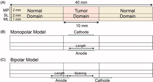
The tumor tissue was set at the middle of the model and was 10.0 mm in length. The other regions were defined as normal tissue () and were considered to have isotropic and homogeneous electrical and thermal properties, as obtained from previous studies [Citation22,Citation34–37] and an open database [Citation38] (). The parameters of the tumor were set similar to those of normal tissue due to lack of model data in literature.
Table 1. Electrical and thermal properties of biological tissue and electrode.
Two configurations of the catheter-based electrodes were considered: monopolar model (MPM) and bipolar model (BPM) ()). In the MPM, the anode and cathode electrodes were located inside and outside the digestive wall, respectively. In the BPM, the anode and cathode electrodes were both located inside the digestive tract. The electrode thickness was set to 0.2 mm, and the lengths of both the anode and cathode electrodes were set to the same value.
Calculation of electric field distribution
The electric field distribution was determined by solving the governing Laplace equation, as described in literature [Citation3,Citation39]:
(1)
(1)
where σ is the electrical conductivity of the tissue, and φ is the electrical potential at a specific location.
Calculation of temperature distribution
The temperature distribution was determined by solving a modified Pennes bioheat transfer equation [Citation24,Citation29,Citation40]:
(2)
(2)
(3)
(3)
where k is the thermal conductivity, T is the temperature, ωb is the blood perfusion rate, cb is the heat capacity of the blood, Ta is the arterial temperature, Qm is the metabolic heat generation of the tissue, QJoule is the Joule heating that accounts for resistive heating of tissue, ρ is the tissue density and ct is the heat capacity of tissue.
Tissue electrical conductivity
The tissue electrical conductivity was determined using the following equation to incorporate changes due to electroporation and thermal effect [Citation24,Citation26,Citation41,Citation42]:
(4)
(4)
where σ0 is the baseline electrical conductivity, A is the multiplication factor, α is the conductivity–temperature coefficient, T is the temperature, and T0 is the physiological temperature. flc2hs is a smoothed Heaviside function defined in Comsol software with a continuous second derivative. This function changes from zero to one over the range ± Erange, and Edelta is the value at which transition occurs [Citation43]. In fact, A, Erange and Edelta are specific to the tissue of interest. These data were chosen based on values commonly found in the literature [Citation34,Citation41]. The conductivity–temperature coefficient ranges from 0.01 to 0.03 1/K, and a value of 0.02 1/K was selected in this study.
Calculation of cell death probability during IRE
The Peleg–Fermi model was used to calculate cell death probability by EI during IRE, which was taken from a report by Golberg et al. [Citation26]:
(5)
(5)
where S is the proportion of surviving cells after IRE and E is the electrical field strength. Ec(n) and A(n) are two functions that depend on the number of pulses:
(6)
(6)
(7)
(7)
where E0 (399 600 V/m), A0 (144 100 V/m), k1 (0.03) and k2 (0.06) are the regression coefficients and are related to the pulse duration and cell type. Because there was no available data for digestive tumor, the regression coefficients were obtained from an in vitro study of prostate cancer cells [Citation44]. The probability of cell death due to EI can be calculated as follows:
(8)
(8)
When the value of the probability of EI in a certain region is greater than 0.99 (PEI > 0.99), it can be treated as IRE.
Calculation of TI probability during IRE
The TI was calculated using the Arrhenius rate equation [Citation22,Citation25,Citation30]:
(9)
(9)
where R is the universal gas constant (8.314 J/(mol·K)), ξ is the frequency factor (7.39 × 1039 1/s), Ea is the activation energy (2.577 × 10⁵ J/mol), T(t) is the temperature distribution at a specific time and τ is the heating time. The temperature distribution is calculated using EquationEquation (2)
(2)
(2) . The frequency factor and activation energy are tissue-specific parameters that describe different modes of TI [Citation45–47]. The probability of cell death due to TI can be calculated as follows:
(10)
(10)
When the value of the Probability of TI in a certain region was greater than 0.99 (PTI > 0.99), it can be treated as irreversible injury.
Boundary and initial conditions
The Dirichlet boundary condition is applied to the electrode–tissue interface. The anode electrode is set as having a positive potential, and the cathode electrode is set to zero:
(11)
(11)
(12)
(12)
where V0 is the potential difference across the electrodes. The outer boundary of the tissue were set as electrical insulating [Citation24,Citation34,Citation35,Citation41].
The initial temperature of the tissue and artery was set to 37 °C (310.15 K), which is the normal physiological body temperature. The internal boundaries between the tissue and electrodes were defined as thermally continuous. The external boundaries of the tissue and electrodes were defined as adiabatic to confine the heat generated during IRE within the tissue completely, depending on which the upper limits of Joule heating can be calculated [Citation24,Citation35,Citation48].
IRE and electrode parameters
Typically, a set of 100 pulses with 100 μs duration is delivered to the tissue during IRE. The voltage of each pulse ranges from 1.00 to 3.00 kV [Citation5]. In this study, the pulse voltage (V), electrode length (l), electrode spacing (d) and pulse number (N) were varied to investigate the tissue injury by a parametric study. In the MPM, the electrode length was the only parameter that changed in the electrode geometry. The base value, range and step length of each parameter is summarized in .
Table 2. Base value, range and step length of each parameter.
Numerical analysis
The finite element method was used to solve the numerical models in this study. The model and numerical analyses were constructed and executed using commercial COMSOL Multiphysics 5.4 software (COMSOL, Inc., Burlington, MA). A convergence test of the mesh model was performed to ensure validity and stability of the simulation [Citation24,Citation35]. The detailed data of the mesh model are summarized in the Supplementary Files.
The electric field distribution was calculated for a single pulse by performing a stationary study. The lethal threshold of EFS for IRE varies in tissues and may not be the same for normal and cancerous tissue. Owing to a lack of data for each layers in the digestive tract, the lethal threshold for IRE was taken as 500 V/cm for all the three layers as used in the small intestine from literature [Citation34]. If the value of EFS was greater than the threshold, it was treated as effective electric fields (EEF). The total area of the EEF in each model was calculated. For pulse setting, the pulse duration and frequency were set to 100 μs and 1 Hz. The effects of the electrode configuration and pulse voltage on the electrical and thermal injuries were calculated for 100 pulses to evaluate the time accumulated effects of the pulses. To evaluate each model quantitatively, the relative area ratio (RAR) was defined as the ratio of the valid area of a certain evaluation index to the total area of the domain. The RAR was calculated separately for the EEF, PEI > 0.99, and PTI > 0.99 of each domain.
To reduce unnecessary injury, the minimum number of pulses (Nmin) required to reach IRE in the tumor tissue was calculated in each model. The distributions of the electrical fields, temperature, electrical conductivity and tissue injury at Nmin were also calculated. Tissue will be affected thermally when the temperature exceeds the threshold of 43 °C for a while [Citation49]. Therefore, 43 °C was selected as the threshold for thermal effect. If the average temperature of tumor tissue at Nmin was less than 43 °C, it was considered as nonthermal-IRE (NT-IRE). If the average temperature of tumor tissue at Nmin was greater than 43 °C but the RAR of PTI > 0.99 was zero, it was considered as thermal-IRE (T-IRE). Other cases should be deprecated in case of TI. The results obtained using each configuration were compared. These data were analyzed in GraphPad 7.0 (GraphPad Software Inc., La Jolla, CA).
Results
Effects of electrode configuration and pulse settings on electric fields distribution
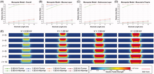
shows the effects of the electrode length and pulse voltage on electric field distribution in the MPM. As the electrode length increases, the RAR of EEF in the tumor tissue gradually increases from 0.81 at 5 mm to 1.00 at 8 mm when the voltage is 0.50 kV, which means complete coverage of EEF in the tumor tissue. Meanwhile, the RAR of EEF in the normal tissue increases from 0.00 at 5 mm to 0.03 at 8 mm and reaches 0.10 at 10 mm, indicating that more of the normal tissue was covered by the EEF. When the voltage is greater than 1.00 kV, the RAR of EEF in the tumor tissue is 0.98 at 5 mm, indicating that the voltage is sufficiently strong to cover the entire tumor tissue within the EEF. As the voltage increases, the RAR of EEF in the normal tissue increases and even reaches 0.23 at 10 mm electrode length. Generally, the RAR of EEF in different layers have the same variation trend (). Specifically, the EFS is greater in the SL and MP, which may be due to the difference in electrical properties. The distribution of EEF expands to the surrounding normal tissue on both sides with increasing electrode length or pulse voltage. Moreover, the regions near the edges of the electrodes present greater EFS than others.
Figure 2. Effects of electrode length and pulse voltage on the distribution of electric fields in monopolar model. (A) RAR of EEF in digestive tract for different electrode lengths and pulse voltages. (B) RAR of EEF in mucosa for different electrode lengths and pulse voltages. (C) RAR of EEF in submucosa for different electrode lengths and pulse voltages. (D) RAR of EEF in muscularis propria for different electrode lengths and pulse voltages. (E) Distribution of electric fields for different electrode lengths and voltages. EEF: effective electric field; ML: mucosal layer; MP: muscularis propria; SL: submucosal layer; RAR: relative area ratio; V: voltage; l: electrode length.
shows the effects of the electrode length and pulse voltage the distribution of electric fields with different electrode spacing in the BPM. It is obvious that increasing the electrode length does not affect the RAR of EEF and distribution of electrical fields in the tumor tissue, which means that electrode length is not the critical parameter. When the electrode spacing is 5 mm, the RAR of EEF in the tumor tissue is 0.43, 0.91, 1.00 and 1.00 at 0.50, 1.00, 1.50 and 2.00 kV, respectively (). Similarly, as the voltage increases, the RAR of EEF in the normal tissue increases from 0.00 to 0.07. Therefore, higher voltage will increase the coverage of electric fields in the normal tissue, which may cause more unnecessary injury. Because the anode and cathode electrode are directly in contact with the ML, the coverage of EEF expands from the ML to the other layers with increasing voltage. The EFS is greater in regions near the edges of the electrodes ().
Figure 3. Effects of electrode length and pulse voltage on the distribution of electric fields for different electrode spacing in bipolar model. (A–F) RAR of EEF in digestive tract for different electrode lengths and pulse voltages (d ranges from 5 to 10 mm). (G) Distribution of electric fields for different electrode lengths (V = 1.00 kV, d = 5 mm). (H) Distribution of electric fields for different pulse voltages (d = 5 mm, l = 5 mm). V: voltage; d: electrode spacing; l: electrode length; EEF: effective electric field; RAR: relative area ratio.
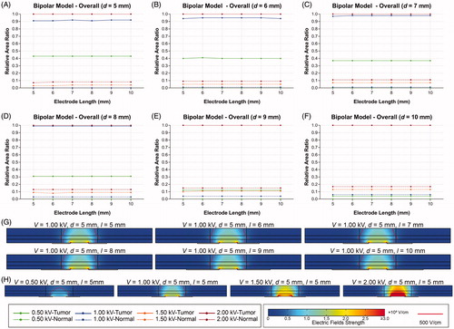
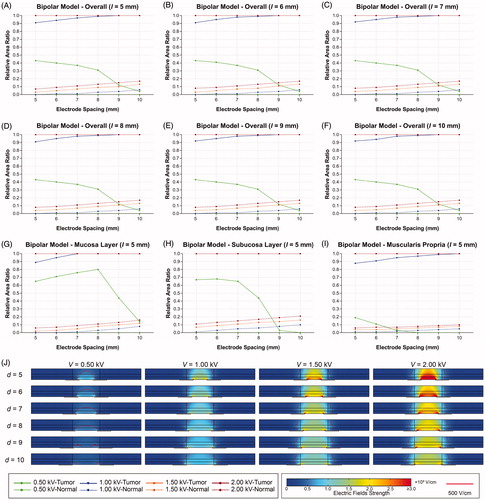
shows the effects of the electrode spacing and voltage on the distribution of electric fields in the BPM. The RAR of EEF gradually decreases from 0.43 to 0.04 as the electrode spacing increases from 5 to 10 mm at the voltage of 0.50 kV. The coverage of EEF is gradually reduced to the periphery of the electrode from the entire layers of tissue. When the voltage is greater than 1.00 kV, the RAR of EEF rapidly increases from 0.91 to 1.00 in the tumor tissue, and 0.00 to 0.20 in the normal tissue. The detailed data of EEF are summarized in the Supplementary Files.
Figure 4. Effects of electrode spacing and pulse voltage on electric field distribution in bipolar model. (A–F) RAR of EEF in digestive tract for different electrode spacing and pulse voltages (l ranges from 5 to 10 mm. (G) RAR of EEF in mucosa for different electrode spacing and pulse voltages. (H) RAR of EEF in submucosa for different electrode spacing and pulse voltages. (I) RAR of EEF in muscularis propria for different electrode spacing and pulse voltages. (J) Distribution of electric fields for different electrode spacing and pulse voltages. V: voltage; d: electrode spacing; l: electrode length; EEF: effective electric field; ML: mucosal layer; SL: submucosal layer; MP: muscularis propria; RAR: relative area ratio.
Effects of pulse number on electrical and thermal injuries of tissue
and show the variation trends of RAR of PEI > 0.99 and PTI > 0.99 for 100 pulses in the tumor tissue. In the MPM, increasing the voltage reduces Nmin as well as increases the risk of TI with the same electrode length. At the voltage of 0.50 kV, the EI increases much faster than the TI, and even no TI occurred at Nmin. However, the increasing rate of TI is significantly elevated when the voltage is equal or greater than 1.00 kV. TI even occurs earlier than EI when the voltage is greater than 1.00 kV. Increasing the electrode length will enlarge the distribution of EEF in the tumor tissue and reduce the Nmin, but the risk of TI increases as a result. The RAR of PEI > 0.99 increased in steps and the steepness of growth curve increased with the increasing of electrode length. However, the RAR of PTI > 0.99 increased monotonically after exceeding the TI threshold.
Figure 5. Effects of electrode length and pulse voltage on electrical and thermal injury by 100 pulses in the tumor tissue of the monopolar model. (A) l = 5 mm. (B) l = 6 mm. (C) l = 7 mm. (D) l = 8 mm. (E) l = 9 mm. (F) l = 10 mm. l: electrode length.
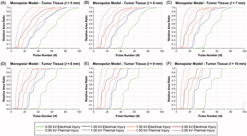
Figure 6. Effects of electrode spacing and pulse voltage on electrical and thermal injury by 100 pulses in the tumor tissue of the bipolar model. (A) d = 5 mm. (B) d = 6 mm. (C) d = 7 mm. (D) d = 8 mm. (E) d = 9 mm. (F) d = 10 mm. d: electrode spacing.
summarizes the RAR of PEI > 0.99, PTI > 0.99, average temperature of tissue, and outcomes at Nmin in the MPM. Despite no TI occurred when voltage is 0.50 kV, the average temperature were greater than 43 °C in the tumor tissue, which means that the thermal effect is inevitable in the MPM. When voltage is greater than 1.00 kV, the RARs of PTI > 0.99 at Nmin were 1.00 in each protocol. Therefore, these protocols were not acceptable for IRE.
Table 3. Relative area ratio of EI0.99, TI0.99, average temperature of tissue and outcomes at Nmin in the monopolar model.
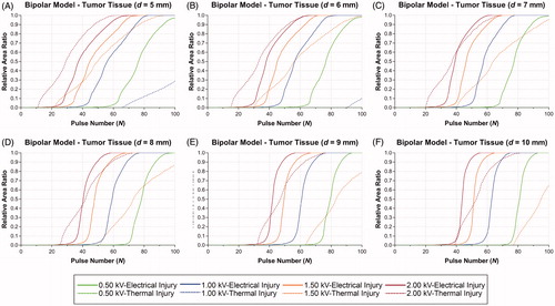
In the BPM, increasing the voltage can reduce Nmin but also increases the risk of TI in the tumor tissue at the same electrode spacing. When the electrode spacing was 5.0 mm, the EI increase much faster than TI at the voltage of 0.50 and 1.00 kV. Otherwise, TI occurs earlier than EI when voltage is equal or greater than 1.50 kV. While there is a cross point in growth curve of EI and TI at the voltage of 1.50 kV. With the increasing of electrode spacing, the distribution of EEF enlarged, which leads to the decreasing of the Nmin and risk of TI. In addition, the occurrence time of TI delayed, but the steepness of growth curve for EI was increased. In the BPM, the RAR of PEI > 0.99 and PTI > 0.99 increased monotonically, which was different from the MPM.
summarizes the RAR of PEI > 0.99, PTI > 0.99, average temperature, and outcomes at Nmin in the BPM. At 0.50 kV, the RARs of PTI > 0.99 are zero and the average temperature are below 43 °C, which means that the tissue is only affected by EI. Therefore, 0.50 kV is the ideal voltage for achieving NT-IRE in the BPM. At 1.00 kV, despite the RARs of PTI > 0.99 are zero, the average temperature of tissue are greater than 43 °C, therefore the tissue will be affected by thermal effect to some extent. When the voltage is 1.50 kV, the RARs of PTI > 0.99 were greater than zero except 10 mm in electrode spacing.
Table 4. Relative area ratio of EI0.99, TI0.99, average temperature of tissue, and outcomes at Nmin in the bipolar model.
Distributions of electrical and thermal injury
shows the distributions of the electrical conductivity, electric fields, temperature, EI and TI at Nmin. In the MPM (), the distribution of electric fields presents as inverted trapezoid, which may due to the differences in electrical properties among the three layers. The distribution of electrical conductivity was dynamically changed with electrical fields and temperature. Thus, electrical conductivity was elevated for regions located within the target area. With the increasing of voltage, the distribution of EEF expands from the center of the tumor tissue to around. Similarly, the hyperthermia region (within red line) enlarged as well, where the tissue will be affected by thermal effect and even lead to TI. The distribution of EI presents with similar shape with electrical fields. The transition region was narrow and the boundary was relatively clear. The distribution of TI presents with approximate rectangular shape. Moreover, the MP was more susceptible to be affected by thermal effect.
Figure 7. Distributions of electrical conductivity, electric fields, temperature and electrical and thermal injury at Nmin. (A) MPM V = 0.50 kV, l = 5 mm, N = 100. (B) MPM V = 1.00 kV, l = 5 mm, N = 81. (C) MPM V = 1.50 kV, l = 5 mm, N = 72. (D) MPM V = 2.00 kV, l = 5 mm, N = 63. (E) BPM V = 0.50 kV, d = 5 mm, N = 100. (F) BPM V = 1.00 kV, d = 5 mm, N = 82. (G) BPM V = 1.50 kV, d = 5 mm, N = 74. (H) BPM V = 2.00 kV, d = 5 mm, N = 68. EI: electrical injury; TI: thermal injury; OI: overall injury; V: voltage; l: electrode length; N: pulse number; σ: electrical conductivity; E: electric field; T: temperature.
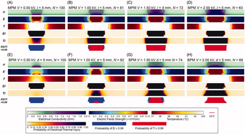
In the BPM ()), since the couple of electrodes were directly in contact with ML, tumor tissue in ML and between the electrodes present greater EFS than others. As a result, the electrical conductivity and temperature in ML were greater, which means ML was more susceptible to electrical and thermal effect. The distribution of EI was similar with the MPM. While the shape of TI was trapezoid that the width of injury in ML was larger than others.
Comparison of outcomes with different electrode configurations and pulse settings
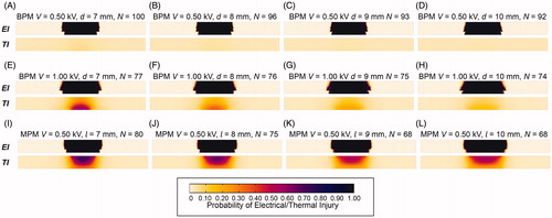
In total, 48 IRE protocols were investigated. There were 6 NT-IRE protocols, 12 T-IRE protocols and 30 TI protocols ( and ). All of the NT-IRE protocols were set in the BPM with a voltage of 0.50 kV. With the increasing of electrode spacing, the average temperature of tumor tissue and Nmin decreases (). For the T-IRE protocols, average temperature in the tumor tissue were greater than 43 °C, which means inevitable thermal effect following with IRE (). The distribution and intensity of thermal effect was different between this two models. For TI protocols, the RARs of PTI > 0.99 were greater than zero, which should be avoided for IRE. It is obvious that the risk of TI in the MPM is greater than the BPM. For the BPM, voltage of 0.50 kV was ideal for NT-IRE, and voltage of 1.00 and 1.50 kV were also acceptable with controllable thermal effect. While only 0.50 kV is acceptable in the MPM.
Figure 8. Distributions of electrical injury and thermal injury at Nmin in IRE protocols. (A) BPM V = 0.50 kV, d = 7 mm, N = 100; (B) BPM V = 0.50 kV, d = 8 mm, N = 96; (C) BPM V = 0.50 kV, d = 9 mm, N = 93; (D) BPM V = 0.50 kV, d = 10 mm, N = 92; (E) BPM V = 1.00 kV, d = 7 mm, N = 77; (F) BPM V = 1.00 kV, d = 8 mm, N = 76; (G) BPM V = 1.00 kV, d = 9 mm, N = 75; (H) BPM V = 1.00 kV, d = 10 mm, N = 74; (I) MPM V = 0.50 kV, l = 7 mm, N = 80; (J) MPM V = 0.50 kV, l = 8 mm, N = 75; (K) MPM V = 0.50 kV, l = 9 mm, N = 68; (L) MPM V = 0.50 kV, l = 10 mm, N = 68. V: voltage; d: electrode spacing; N: pulse number; σ: electrical conductivity; E: electric field; T: temperature; EI: electrical injury; TI: thermal injury; OI: overall injury.
At a voltage of 0.50 kV, Nmin was the same (N = 93) in the MPM (l = 5 mm) and the BPM (d = 6 mm) ( and ). Therefore, these two protocols were selected for further investigation. shows the changing trend and distribution of temperature during one pulse. In general, tumor tissues present heating and cooling phases during one pulse. The duration of the heating phase was associated with pulse duration, which was ultra-short compared to that for the cooling phase. At a voltage of 0.50 kV, the maximum temperature of the tissue-electrode boundary in the MPM was significantly greater than that in the BPM (44.72 °C versus 38.24 °C). Therefore, the accumulated heat in the MPM was greater than that in the BPM because of the equal duration of cooling phases. shows the temperature distribution after one pulse. shows the changing trend of the average temperature in the tumor tissue during 100 pulses. The average temperature of the tumor tissue in the MPM was greater than that in the BPM at Nmin (51.43 °C versus 38.03 °C).
Figure 9. Comparison of the monopolar model (l = 5 mm) and bipolar model (d = 6 mm) at a Voltage of 0.50 kV. (A) Changing trend of temperature during one pulse. (B) Distribution of temperature at the end of one pulse in the MPM (upper) and the BPM (bottom). (C) Changing trend of average temperature in the tumor tissue during 100 pulses. (D) RAR of EI0.99 and TI0.99 in different layers of the digestive tract for 100 pulses in the MPM (solid line) and the BPM (imaginary line). (E) Distribution of electrical injury at 25, 50, 75 and 100 pulses in the MPM (upper) and the BPM (bottom). (F) Distribution of thermal injury at 25, 50, 75 and 100 pulses in the MPM (upper) and the BPM (bottom). V: voltage; d: electrode spacing; l: electrode length; N: pulse number; MPM: monopolar model; BPM: bipolar model; ML: mucosal layer; SL: submucosal layer; MP: muscularis propria.
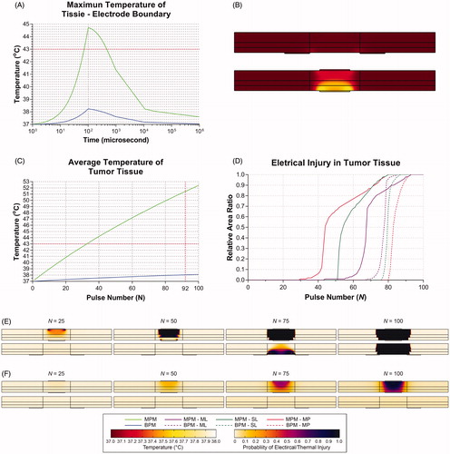
shows the RAR of PEI > 0.99 in the different layers of the digestive tract for 100 pulses. In the MPM and the BPM, Nmin is 93, 80 and 80 and 85, 87 and 93 for ML, SL and MP, respectively. shows the distribution of EI and TI at 25, 50, 75 and 100 pulses. MP was affected by EI before the other layers in the MPM, while it occurs first for ML in the BPM. Moreover, the thermal effect in the MPM is more significant than in the BPM.
Discussion
Catheter-based IRE under endoscopy is an attractive minimally invasive technique for tissue ablation in the digestive tract. To improve the safety and efficacy of the IRE, electrical and thermal analyses of the electrode configuration and pulse settings are necessary. In this study, the electrical and thermal injuries of IRE in the digestive tract were investigated on a 4-mm-thick digestive tract model using two catheter-based electrode configurations. Electrode length is the key geometric parameter of the electrode for electric field distribution in the tumor tissue in the MPM, while it plays no role in the BPM; meanwhile, electrode spacing affects the outcomes in the BPM. Increasing the pulse voltage reduces the pulse number required for tissue ablation, while it increases the risk of TI as well. Moreover, it is more susceptible to thermal effects in the MPM. Compared with the MPM, the BPM is more reliable and safer for achieving the NT-IRE in 4-mm-thick digestive wall.
Electric conductivity is a key parameter in the calculation of electric fields. Previous studies demonstrated that electric conductivity dynamically changes from the baseline to higher values in the steps depending on EFS and the temperature [Citation36,Citation41,Citation42]. An electro-thermal coupling function (EquationEquation (4)(4)
(4) ) was introduced to calculate the electrical conductivity during IRE by Garcia et al. [Citation43]. Thus, the distribution of electric fields may change because of the dynamically changed electrical conductivity during IRE. Despite that, it is necessary to perform stationary analysis for determining the electric field distribution to predict the ranges of the ablation zone.
The total energy delivered to the tissue depends on pulse duration and number [Citation23,Citation25]. The Peleg-Fermi model incorporates the EFS and pulse number to calculate the probability of cell death caused by EI during IRE [Citation26]. Garcia et al. performed a numerical investigation of EI and TI in electroporation-based therapies for the liver [Citation22]. In this manner, pulse parameters were optimized to achieve IRE successfully. It is obvious that increasing the pulse number will ensure sufficient EI. However, it will also increase the risk of TI that should be avoided for NT-IRE. Therefore, the minimum pulse number required for IRE and the occurrence time of TI should be calculated to prevent unnecessary injury to the tissue. The growth curve of the electrical and thermal injuries were calculated and evaluated in this study. This allowed the prediction of the limitation of the pulse number and the outcomes of the protocol and the suggestion of suitable protocols for the physician.
The thermal effect on the tissue is inevitable in conditions with greater EFS or under certain electrode configurations. The temperature rise is significant in areas near the electrode-tissue boundary or at the edge of the electrode; thus, thermal coagulation of the tissue may occur in this area [Citation28]. Despite this, the average tissue temperature and area of hyperthermia can be controlled by adjusting the electrode configuration or pulse settings. The risk of TI was reduced with an increase in electrode spacing in the BPM or the electrode length in the MPM under the same voltage.
Catheter-based electrodes were widely used in RFA and other techniques [Citation50]. In general, a grounding pad is required to fix the surface of the body as the cathode to return the current. Therefore, only anode electrode is required for endoscopic catheters. However, the relative position of the anode and the cathode is critical for forming electric fields in IRE. Currently, there are no studies that investigate electrode configuration and pulse settings in catheter-based IRE. In this study, two catheter-based IRE electrode models were constructed to evaluate the efficacy in the digestive tract. Owing to the anatomy of the digestive tract, the electrode can be placed inside or outside of the lumen by endoscopy to prevent perforation or mechanical injury.
The BPM demonstrated sufficient efficacy to cause EI to tumor tissue without TI at several voltage. Since a couple of electrodes were directly in contact with ML, EI and the thermal effect first occurred in ML and then extended to SL and MP with an increase in the pulse number. Tissue injury occurred earlier in MP than the others in the MPM. Therefore, the IRE depth can be controlled in selected layers for different types and stages of tumor owing to this time-order feature. The MPM can reduce the pulse number required for the IRE; however the thermal effect is inevitable during IRE especially in MP, which is the most important layer in forming gastrointestinal wall integrity [Citation51]. Therefore, the digestive wall faces the risk of perforation in the MPM.
For the endoscopic approach, the cathode electrode needs to be placed into the abdominal cavity by laparoscopy or open surgery in the MPM [Citation17], while a couple of the electrodes can be placed into the digestive tract together in the BPM [Citation15]. Therefore, the BPM is a more minimally invasive approach than the MPM. However, because the electrical and thermal analyses of the two configurations are based on numerical models, experimental studies should be performed in the future.
There were several limitations in this study. First, the thickness of the tumor was set to be the same as that of normal tissue. However, the tumor may have an irregular form and be larger and thicker. Even then, the results of electrical and thermal analyses will provide valuable guidance for electrode design and manufacture in the future. For tumors with a larger size, IRE can be performed by moving catheter for times. Second, the tissue was assumed to be isotropic and homogeneous, while the actual properties of tissue are more complex. Large blood vessels in the digestive wall may influence tissue conductivity through a potential electric-sink effect [Citation37]. Moreover, the electrical and thermal properties are different for normal and tumor tissues, which should be investigated in the future. Finally, this is a numerical study, and the results are based on theoretically analyses, which need to be further validated through an in vivo study in the future.
Conclusion
In this study, parametric study of electrical and thermal analyses of catheter-based IRE of the digestive tract were performed. The electrode configuration and pulse settings could be adjusted to achieve NT-IRE synergistically. Compared with MPM, BPM is more reliable for achieving NT-IRE in 4 mm-in-thickness digestive wall. These results are very helpful and of great clinical significance for catheter-based electrode configuration and treatment planning from a theoretical standpoint. Future in vitro and in vivo studies are needed to support and validate this conclusion.
Supplemental Material
Download PDF (1.5 MB)Supplemental Material
Download PDF (974.1 KB)Acknowledgements
We would like to thank the High Performance Computing (HPC) Platform of Xi’an Jiaotong University for the support of model construction and numerical analysis.
Disclosure statement
No potential conflict of interest was reported by the authors.
Data availability statement
The data that support the findings of this study are available from the corresponding author R. Wu and Y. Lv upon reasonable request.
Additional information
Funding
Related Research Data
References
- Davalos RV, Mir LM, Rubinsky B. Tissue ablation with irreversible electroporation. Ann Biomed Eng. 2005;33:223–231.
- Miller L, Leor J, Rubinsky B. Cancer cells ablation with irreversible electroporation. Technol Cancer Res Treat. 2005;4:699–705.
- Rubinsky B, Onik G, Mikus P. Irreversible electroporation: a new ablation modality - clinical implications. Technol Cancer Res Treat. 2007;6:37–48.
- Golberg A, Yarmush ML. Nonthermal irreversible electroporation: fundamentals, applications, and challenges. IEEE Trans Biomed Eng. 2013;60:707–714.
- Jiang C, Davalos RV, Bischof JC. A review of basic to clinical studies of irreversible electroporation therapy. IEEE Trans Biomed Eng. 2015;62:4–20.
- Chu KF, Dupuy DE. Thermal ablation of tumours: biological mechanisms and advances in therapy. Nat Rev Cancer. 2014;14:199–208.
- Yarmush ML, Golberg A, Serša G, et al. Electroporation-based technologies for medicine: principles, applications, and challenges. Annu Rev Biomed Eng. 2014;16:295–320.
- Maor E. Nonthermal irreversible electroporation for tissue decellularization. J Biomech Eng. 2010;132:091003.
- Hall SK, Ooi EH, Payne SJ. Cell death, perfusion and electrical parameters are critical in models of hepatic radiofrequency ablation. Int J Hyperthermia. 2015;31:538–550.
- Donadon M, Solbiati L, Dawson L, et al. Hepatocellular carcinoma: the role of interventional oncology. Liver Cancer. 2017;6:34–43.
- Stillström D, Nilsson H, Jesse M, et al. A new technique for minimally invasive irreversible electroporation of tumors in the head and body of the pancreas. Surg Endosc. 2017;31:1982–1985.
- Knavel EM, Brace CL. Tumor ablation: common modalities and general practices. Tech Vasc Interv Radiol. 2013;16:192–200.
- Srimathveeravalli G, Cornelis F, Wimmer T, et al. Normal porcine ureter retains lumen wall integrity but not patency following catheter-directed irreversible electroporation: imaging and histologic assessment over 28 days. J Vasc Interv Radiol. 2017;28:913–919.e1.
- Lee EW, Chen C, Prieto VE, et al. Advanced hepatic ablation technique for creating complete cell death: irreversible electroporation. Radiology. 2010;255:426–433.
- Srimathveeravalli G, Wimmer T, Monette S, et al. Evaluation of an endorectal electrode for performing focused irreversible electroporation ablations in the swine rectum. J Vasc Interv Radiol. 2013;24:1249–1256.
- Ueshima E, Schattner M, Mendelsohn R, et al. Transmural ablation of the normal porcine common bile duct with catheter-directed irreversible electroporation is feasible and does not affect duct patency. Gastrointest Endosc. 2018;87:300.e1–300.e6.
- Ren F, Li Q, Hu L, et al. Safety and efficacy of magnetic anchoring electrode-assisted irreversible electroporation for gastric tissue ablation. Surg Endosc. [Internet]. 2019; Available from: http://link.springer.com/10.1007/s00464-019-06800-3
- Yang Y, Zhang B, Moser M, et al. Analysis and optimization of determining factors in irreversible electroporation for large ablation zones without thermal damage. Biomed Biotechnol Eng. 2018. Available from: http://proceedings.asmedigitalcollection.asme.org/proceeding.aspx?doi=10.1115/IMECE2017-70810.
- Singal A, Ballard JR, Rudie EN, et al. A review of therapeutic ablation modalities. J Med Dev. 2016;10:040801.
- Srimathveeravalli G, Silk M, Wimmer T, et al. Feasibility of catheter-directed intraluminal irreversible electroporation of porcine ureter and acute outcomes in response to increasing energy delivery. J Vasc Interv Radiol. 2015;26:1059–1066.
- Lee JM, Choi HS, Chun HJ, et al. EUS-guided irreversible electroporation using endoscopic needle-electrode in porcine pancreas. Surg Endosc. 2019;33:658–662.
- Garcia PA, Davalos RV, Miklavcic D. A numerical investigation of the electric and thermal cell kill distributions in electroporation-based therapies in tissue. PLoS One. 2014;9:e103083.
- Yang Y, Moser MAJ, Zhang E, et al. Development of a statistical model for cervical cancer cell death with irreversible electroporation in vitro. PLoS One. 2018;13:1–18.
- Nickfarjam A, Firoozabadi S. Parametric study of irreversible electroporation with different needle electrodes: electrical and thermal analysis. Int J Hyperthermia. 2014;30:335–347.
- Hall SK, Ooi EH, Payne SJ. A mathematical framework for minimally invasive tumor ablation therapies. Crit Rev Biomed Eng. 2014;42:383–417.
- Golberg A, Rubinsky B. A statistical model for multidimensional irreversible electroporation cell death in tissue. Biomed Eng Online. 2010;9:1–9.
- Ruarus AH, Vroomen LGPH, Puijk RS, et al. Conductivity rise during irreversible electroporation: true permeabilization or heat? Cardiovasc Intervent Radiol. 2018;41:1257–1266.
- Faroja M, Ahmed M, Appelbaum L, et al. Irreversible electroporation ablation: is all the damage nonthermal? Radiology. 2013;266:462–470.
- Ghanbari P, Hajj M. Finite element analysis of tissue electropermeability through the application of electric pulses. Bioeng Biomed Sci. 2013;3:1–7.
- Shafiee H, Garcia PA, Davalos RV. A preliminary study to delineate irreversible electroporation from thermal damage using the Arrhenius equation. J Biomech Eng. 2009;131:074509.
- Yazar FM, Baykara M, Karaağaç M, et al. The role of conventional ultrasonography in the evaluation of antrum wall thickness in obese patients. Obes Surg. 2016;26:2995–3000.
- Rawlins L, Rawlins MP, Teel D. Human tissue thickness measurements from excised sleeve gastrectomy specimens. Surg Endosc. 2014;28:811–814.
- Abu-Ghanem Y, Meydan C, Segev L, et al. Gastric wall thickness and the choice of linear staples in laparoscopic sleeve gastrectomy: challenging conventional concepts. Obes Surg. 2017;27:837–843.
- Phillips M. The effect of small intestine heterogeneity on irreversible electroporation treatment planning. J Biomech Eng. 2014;136:091009.
- Yang Y, Moser M, Zhang E, et al. Optimization of electrode configuration and pulse strength in irreversible electroporation for large ablation volumes without thermal damage. Asme J Med Diagnos. 2018;1:021002.
- Beitel-White N, Bhonsle S, Martin RCG, et al. Electrical characterization of human biological tissue for irreversible electroporation treatments. 2018 40th Annu. Int. Conf. IEEE Eng. Med. Biol. Soc. [Internet]. IEEE; 2018; p. 4170–4173. Available from: http://www.ncbi.nlm.nih.gov/pubmed/30441274.
- Golberg A, Bruinsma BG, Uygun BE, et al. Tissue heterogeneity in structure and conductivity contribute to cell survival during irreversible electroporation ablation by “electric field sinks”. Sci Rep. [Internet]. 2015;5:8485. Available from: http://www.nature.com/articles/srep08485
- Hasgall PA, F Di Gennaro, Baumgartner C, et al. IT'IS Database for thermal and electromagnetic parameters of biological tissues, Version 4.0, May 15, 2018. DOI: 10.13099/VIP21000-04-0.
- Rubinsky B. Electrical field and temperature model of nonthermal irreversible electroporation in heterogeneous tissues. J Biomech Eng. 2009;131:071006.
- Pennes HH. Analysis of tissue and arterial blood temperatures in the resting human forearm. J Appl Physiol. 1948;1:93–122.
- Zhao Y, Bhonsle S, Dong S, et al. Characterization of conductivity changes during high-frequency irreversible electroporation for treatment planning. IEEE Trans Biomed Eng. 2018;65:1810–1819.
- Neal RE, Garcia PA, Robertson JL, et al. Experimental characterization and numerical modeling of tissue electrical conductivity during pulsed electric fields for irreversible electroporation treatment planning. IEEE Trans Biomed Eng. 2012;59:1076–1085.
- Garcia PA, Rossmeisl JH, Neal RE, et al. A parametric study delineating irreversible electroporation from thermal damage based on a minimally invasive intracranial procedure. BioMed Eng Online. 2011;10:34.
- Canatella PJ, Karr JF, Petros JA, et al. Quantitative study of electroporation-mediated molecular uptake and cell viability. Biophys J. 2001;80:755–764.
- Brown SL, Hunt JW, Hill RP. Differential thermal sensitivity of tumour and normal tissue microvascular response during hyperthermia. Int J Hyperthermia. 1992;8:501–514.
- Borrelli MJ, Thompson LL, Cain CA, et al. Time-temperature analysis of cell killing of BHK cells heated at temperatures in the range of 43.5 degrees C to 57.0 degrees C. Int J Radiat Oncol Biol Phys. 1990;19:389–399.
- Jacques S, Newman C, He XY. Thermal coagulation of tissues. Liver studies indicate a distribution of rate parameters, not a single rate parameter, describes the coagulation process. Am Soc Mech Eng. Heat Transf. Div. HTD. 1991;189:71–73.
- Maor E, Rubinsky B. Endovascular nonthermal irreversible electroporation: a finite element analysis. J Biomech Eng. 2010;132:031008.
- Dewhirst MW, Viglianti BL, Lora-Michiels M, et al. Basic principles of thermal dosimetry and thermal thresholds for tissue damage from hyperthermia. Int J Hyperthermia. 2003;19:267–294.
- Steel AW, Postgate AJ, Khorsandi S, et al. Endoscopically applied radiofrequency ablation appears to be safe in the treatment of malignant biliary obstruction. Gastrointest Endosc. 2011;73:149–153.
- Quero G, Saccomandi P, Kwak J-M, et al. Modular laser-based endoluminal ablation of the gastrointestinal tract: in vivo dose–effect evaluation and predictive numerical model. Surg Endosc. [Internet]. 2018; Available from: http://link.springer.com/10.1007/s00464-018-6603-4.