
 ?Mathematical formulae have been encoded as MathML and are displayed in this HTML version using MathJax in order to improve their display. Uncheck the box to turn MathJax off. This feature requires Javascript. Click on a formula to zoom.
Abstract
Purpose
We describe a modified Helmholtz induction coil, or Maxwell coil, that generates alternating magnetic fields (AMF) having field uniformity (≤10%) within a = 3000 cm3 volume of interest for magnetic hyperthermia research.
Materials and methods
Two-dimensional finite element analysis (2D-FEA) was used for electromagnetic design of the induction coil set and to develop specifications for the required matching network. The matching network and induction coil set were fabricated using best available practices and connected to a 120 kW industrial induction heating power supply. System performance was evaluated by magnetic field mapping with a magnetic field probe, and tests were performed using gel phantoms.
Results
Tests verified that the system generated a target peak AMF amplitude along the coil axis of ∼35 kA/m (peak) at a frequency of 150 ± 10 kHz while maintaining field uniformity to >90% of peak for a volume of ∼3000 cm3.
Conclusions
The induction coil apparatus comprising three independent loops, i.e., Maxwell-type improves upon the performance of simple solenoid and Helmholtz coils by providing homogeneous flux density fields within a large volume while minimizing demands on power and stray fields. Experiments with gel phantoms and analytical calculations show that future translational research efforts should be devoted to developing strategies to reduce the impact of nonspecific tissue heating from eddy currents; and, that an inductor producing a homogeneous field has significant clinical potential for deep-tissue magnetic fluid hyperthermia.
Introduction
Combining magnetic materials or magnetic fluids with low frequency (50–400 kHz) alternating magnetic fields (AMFs) to treat deep-seated tumors by focal heating has generated interest for several decades [Citation1–9]. Magnetic fluid hyperthermia (MFH) received European Union approval in 2010 for human use in the treatment of glioblastoma [Citation2]. Low- or radio-frequency (RF) AMFs are particularly advantageous for deep tissue applications because they provide high penetration with essentially no tissue attenuation or reflection; and, they generate less nonspecific tissue heating from interactions with tissue than do higher frequency electromagnetic (EM) fields [Citation10,Citation11]. Design of devices for biomedical applications employing low-frequency AMFs thus reduces to well-established engineering considerations for applicator or coil geometries to produce magnetic fields having desired flux density in a specified volume [Citation10,Citation12–15]. Preclinical and clinical experiences with MFH using low-frequency AMFs have established its viability as a treatment for cancer [Citation1–8,Citation16,Citation17].
Design considerations of the coil or inductor geometry must take into account the physics of energy transduction between a magnetic material and the potential for widespread tissue power deposition resulting from interactions with AMFs. Magnetic materials that have been most commonly used with low RF alternating fields in medicine include thermal seeds (small metallic bodies) and fluids containing magnetic nanoparticles, i.e., magnetic fluids or ‘ferrofluid’ [Citation1,Citation3–8,Citation16–25].
When exposed to an AMF, the heat generated by magnetic materials is typically dominated by magnetic hysteresis loss which depends upon the frequency and amplitude of the AMF, and on the magnetic and physical properties of the material [Citation5]. Depending upon the size (i.e., ∼>0.5 mm), conductivity, shape and orientation of the material additional interactions with the external magnetic field can generate heat. For nanometer-scale materials; however, orientation and induction heating effects are negligible, leaving magnetic hysteresis loss to be the primary heating mechanism [Citation5,Citation21].
Low-frequency AMFs (≤10 MHz) are essentially not attenuated by tissue (i.e., muscle-equivalent materials) having radii equal to the human torso, but they induce electric or Foucault currents in such materials to deposit generalized (nonspecific) Joule heating [Citation22,Citation23]. In this case, the heat generated depends upon physical properties and geometric orientation of the tissue exposed, its volume, and on AMF frequency and amplitude [Citation21–32]. A simplified description for tissue heating can be represented by a cylindrical body of uniform conductivity oriented normal to a uniform, unidirectional AMF to estimate the extent of nonspecific power density deposition that leads to tissue heating [Citation21,Citation22].
(1)
(1)
where
is electrical conductivity of the cylinder and r is its radius. While tissue does not attenuate low-frequency AMFs, local field intensity does depend upon the distance from the field source or induction coil. Thus, unless the inductor is designed to produce a uniform field within a volume encompassing the intended target, the field intensity illuminating a particular target volume of tissue depends critically on coil or inductor geometry and placement of the tissue relative to the inductor surface [Citation22].
Eddy current heating of a cylindrical body is thus proportional to the square of Hf and the square of radial distance r from the cylindrical axis [Citation22]. The upper limit of exposure of a human thorax was established from numerous experiments on humans with a single-turn coil operating at 13.56 MHz and varying field amplitudes to 35.8 A/m [Citation22]. From these measurements, Atkinson et al. concluded that extended exposure to low-frequency AMF is well tolerated if the product Hf ≤ 4.85 × 10⁸ A/m·s [Citation22]. They also recommend that for heating with thermal seeds, f ≤ 200 kHz [Citation22]. This upper limit of Hf has been generally accepted, but it should be noted that this limit applies to tissue volumes having diameter equivalent to a human thorax (or torso), and that higher limits can be tolerated for smaller diameter tissues, e.g., limbs or extremities. For all subsequent discussion, it will be assumed that f is fixed at ∼150 kHz, and that the upper limit of field intensity is ∼4 kA/m.
One strategy employed in coil design has been to accept field inhomogeneity in order to reduce power demands, and compensate by increasing field intensity or modifying target position within the inductor and introducing active tissue cooling [Citation33–40]. While this approach simplifies engineering and other device design considerations, clinical application can be more challenging. Inhomogeneous AMFs generate more spatially inhomogeneous energy deposition in the target, which introduces significant challenges for accurate thermal dose estimation and prescriptive treatment execution. Inconsistent or less predictable thermal dose deposition to target and normal tissues in these marginal cases may present clinically nonviable scenarios because these may increase risks to patient safety and reduce efficacy [Citation22,Citation41–43]. The issues presented by inductors generating inhomogeneous fields become more problematic for treating tumors deep within the body. In such cases, one must choose between setting the amplitude of continuous exposure at the safe limit of a volumetric average at the target of 4 kA/m through the cross-section of a torso normal to the direction of the magnetic field with equivalent diameter of ∼30 cm [Citation22,Citation23], thereby reducing the amplitude and heating of targeted deep-seated tumors because of field divergence. Or, field amplitude is raised at the inductor surface to increase amplitude at the target, but at the expense of increasing average volumetric field and thus increased tissue heating (EquationEquation 3(3)
(3) ). Taking these considerations into account, we sought to develop an inductor coil that generates homogeneous flux density AMFs in a substantial cylindrical volume, ∼3 × 103 cm3, as a scale model for testing the strategy that a homogeneous flux density can minimize overall tissue heating while maintaining flux density near the maximum safe limit deep within the body.
Many possible inductor configurations have been considered to generate homogeneous AMFs for hyperthermia with alternating electric currents (AC) [Citation12,Citation13,Citation25,Citation33,Citation35,Citation44,Citation45]. Three basic coil geometries are generally considered: (a) modified air- or solid-core solenoids, some containing additional counter-wound solenoids [Citation13,Citation33,Citation35]; (b) Helmholtz pairs [Citation12,Citation19,Citation44] and, (c) multiple solenoids having specific geometrical placement (e.g., Loney coils) [Citation46,Citation47].
The Helmholtz pair is a special case of coil design that provides uniform field in defined volume but the size of the test volume is also an important consideration when working with a Helmholtz coil [Citation33,Citation44]. External coils, consisting of two identical, coaxial, circular coils separated by a distance equal to the coil radius (Helmholtz pair) generating a nearly uniform magnetic field along the centerline between the coils can deliver local hyperthermia by producing a magnetic field of sufficient intensity in magnetically susceptible materials positioned in the uniform field volume, even if located deep within the body [Citation33]. Helmholtz coils generate these fields with high demands on power (i.e., high reactive power) and significant stray fields, thus limiting their practical utility for many applications [Citation5,Citation33]. For clinical, deep-tissue applications appropriate Helmholtz coils may require reactive power >108 VAR (Volt-Ampere Reactive, see Supplementary Material) for magnetic field strengths of order 101 kA/m. These and other drawbacks have motivated a focus on design and modification of solenoids for many biomedical applications.
Although well-described, Maxwell coils have received little attention for MFH applications [Citation44]. A Maxwell coil may be considered an improvement of a Helmholtz coil for some applications. It consists of three coils oriented on the surface of a virtual sphere [Citation44]. Maxwell coils have been explored for magnetic navigation/steering in blood vessels and magnetic propulsion applications [Citation45,Citation48,Citation49]. Byun et al. [Citation50] have reported induction heating cooker design with three exciting pancake coils, where they consider optimizing the size of the coils and distance between coils to produce uniform temperature.
In this work, we describe design, construction and characterization of a scale prototype modified Maxwell coil suitable for large animal experiments. The prototype device based on three magnetically connected induction coils was designed to generate AMF amplitudes up to 35 kA/m (peak) in a cylindrical volume of ∼3000 cm3 (∼15–20 cm diameter) at a frequency of approximately 150 kHz, while minimizing reactive power and overall power demand [Citation51]. Design and build of the coil set was conducted with a view to provide a template design and validation for future scale up of an inductor suitable to accommodate a human patient (∼60 cm diameter). Results obtained from field mapping and gel phantoms confirm computational and analytical design parameters. Future tests with the scale prototype are intended to provide in vivo validation with larger animal models to motivate construction of a human-scale prototype device.
Methods
Electromagnetic simulations
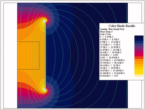
To determine the overall size of the inductor and the required electrical parameters, calculations for a single turn coil were made using 2D-FEA program FLUX 2D (Altair Hyperworks, Troy, MI). A finite element mesh was automatically generated once geometrical parameters and EM values were input. Axisymmetric conditions were assumed, enabling calculations to be performed explicitly using 1/4 of the full coil. The target AMF specifications used to constrain the inductor design included a requirement to generate a uniform (±10%) field having amplitude of about 35 kA/m at a frequency of about 150 kHz over a cylindrical volume having 10 cm length and 16 cm diameter. Generally, a greater volume of uniform field was given preference to higher field amplitude once the target field strength was achieved. When properly sized, a single turn coil (round or oval) is the optimal configuration to minimize the required reactive and active powers in a cylindrical volume greater than 1000 cm3. The length of the coil was varied to find the most favorable to minimize reactive power and maximize field uniformity in the volume of interest. The resulting distribution of magnetic field is shown in . Based upon these calculations, it was determined that the required voltage and current were approximately 1000 V(rms) and 10,000 A(rms), respectively. This means that total apparent power required was at least 10 MVA taking account additional kVA requirements in the circuit, with nearly 100% being reactive power (see Supplementary Material for discussion on reactive power) [Citation51].
Figure 1. 2D Finite element simulations of a single-turn induction coil. Computer simulation of magnetic field strength distribution in a single turn induction coil.
It has been previously described that use of copper rings with brazed copper cooling tubes successfully minimizes azimuthal magnetic field variation [Citation12,Citation13,Citation25]. A similar construction was used to simulate a three-piece induction coil set (a modified Maxwell coil). An expert-driven optimization technique was used to determine the induction coil(s) geometry to produce uniform AMF amplitude up to 35 kA/m in a cylindrical volume of at least 16 cm diameter by 10 cm in length and frequency of 150 ± 10 kHz and match to custom built modular heat stations and capacitors.
The need for multiple coils (and hence the Maxwell coil design) in the set was driven by magnetic energy limits for the individual heat stations [Citation51]. An additional benefit to increase system efficiency was realized by reducing overall dimensions and separation between each coil and capacitance network to reduce distance for current to travel. Losses in the heat station and other power delivery components were determined to exceed those in the coil winding itself, common for applications requiring high Q factor in this frequency range.
Maintaining ambient temperature in the region within the coil to within physiologic temperatures (<37 °C) during operation was a critical design consideration. With insertion of a water jacket to maintain air temperatures within the sample environment at acceptable levels, higher coil surface temperatures can be tolerated; however, moderate coil temperature during operation (∼<80 °C) was an imposed design constraint [Citation40]. An additional constraint for the physical coil diameter was an added 2 cm to accommodate a water jacket within the induction coil.
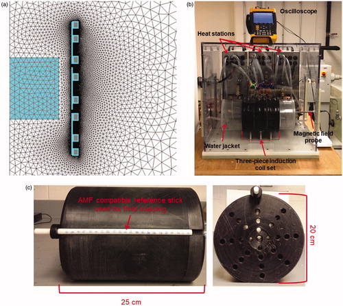
In a final set of simulations for an optimized three-piece induction coil set, the active portion of the coil set construction was simulated to be formed of copper sheets. Brazed water-cooled copper tubes could provide cooling to the copper sheet inductors; similar to the modified solenoid previously described [Citation13]. The number and placement of copper tubes was determined using 2D coupled EM and thermal simulations, to ensure a limited temperature rise in each copper turn. FLUX 2D was used to generate cross-sectional field amplitude data and electrical parameters of the simulated three-piece induction coil set for each adjustment to the design. Data were compared with results from preceding iterations to optimize the design until results were within performance specifications. The inductor design was constrained to an internal diameter of 20 cm to allow for the water jacket. The corresponding mesh consisted of 10,000 triangular elements (). The box in the center of the drawing represents the specified minimum volume of uniformity required.
Figure 2. 2D Finite element simulations of a three-piece induction coil set and image of prototype Maxwell inductor. (a) Coil and mesh diagram from 2D FEA for a three-piece induction coil set. (b) Image showing three-piece induction coil set, heat stations, oscilloscope, magnetic field probe and water jacket. (c) Image of the cylinder used for field mapping. Left photograph is the view along the length of the cylinder, and right shows radial view.
Fabrication of the capacitors, heat stations and the three induction coil set
Each heat station was grounded and contained a low inductance electric busbar for mounting the capacitors. The busbar consisted of four water cooled copper bars arranged in two sets of opposing buss having 16 mounting locations for capacitors. The capacitors on these rails were configured in one of at least two ways. The first possible configuration was to connect all capacitors in parallel when used, e.g., for lower voltage applications as dictated by the selected capacitor ratings. An alternative configuration includes eight sets of capacitors connected in parallel with each set having two capacitors in series. This alternative approach may be used primarily where the maximum voltage is higher than the rated values on the capacitors for the chosen frequency. The latter was chosen because it is more compatible with commercially available capacitors.
After selecting a configuration, the minimum number of capacitors for each heat station was determined. The most favorable capacitors available for this application were rated for 300 kVAR for continuous use over the desired frequency range. It was determined that a minimum of 34 capacitors was required to achieve 10,000 kVAR. Taking into account expected additional reactive power capability required from the coil leads and capacitor rails, three capacitor rails and resulting heat stations were used for full external compensation of the reactive power of the induction system.
Once preliminary calculations were completed, drafting of manufacturing drawings for the heat stations and coil set was conducted and parts were manufactured and assembled. Efforts were taken to minimize the width of each heat station to minimize the length of coil leads and resulting additional requirements for voltage and reactive power compensation. This led to an apparatus comprising three heat stations supplied by a common power source; and three inductors each connected to a heat station, wherein each inductor was configured to magnetically interact with the other inductors to generate high amplitude AMFs. Input terminals of the capacitor battery in the individual heat stations were connected in parallel by a common bus, and the common bus was connected to the power source. Input terminal was electrically connected to the power source and heat stations were energized by induced voltage from an inductor of an adjacent heat station. Each inductor included a single turn coil with substantially the same dimensions, having cooling tubes brazed to a copper plate.
Following fabrication each induction coil was mounted to an external heat station (AMF LifeSystems, LLC, Auburn Hills, MI) connected to a 120 kW, 135–440 kHz industrial induction power (AMF LifeSystems, LLC., Auburn Hills, MI) by a flexible cable (AMF LifeSystems, LLC.). The system was tuned to operate at ∼150 kHz by adjusting the capacitance of the matchbox or the power supply as well as by adjusting the series inductor inside the power supply [Citation51]. The apparatus is shown in .
The power supply, heat stations, cables and coils form a resonant circuit cooled with a closed-loop, circulating water system maintained at a temperature between 22 °C and 28 °C (Dry Cooler Systems, Inc., Auburn Hills, MI). The water system provides cooling from a 200-L reservoir with a flow rate of 100 L/min at 900 kPa.
Characterization of the three induction coil set
A commercial magnetic field probe (AMF Life Systems, LLC, Auburn Hills, MI) was used to characterize the field generated by the coil as previously described [Citation27]. A cylindrical mandrel with holes drilled along the length of the cylinder at various radial positions shown in was used to map the AMF amplitude inside the developed three induction coil set. A custom made rod with 1 cm markings shown in was used to position the magnetic field probe.
Water jacket
A water jacket was designed to maintain a set temperature in specified volume within the coil (sample environment) that would isolate the sample from thermal transfer with the coils during operation. The water jacket was manufactured at Center Line Models Inc. (St. Charles, IL). Briefly, the water jacket was constructed from concentric acrylic tube (inner tube: 6.25″ × 6.5″ × 24″ and outer tube: 7.25″ × 7.5″ × 24″) with internal helical baffles. The ends were sealed and two holes were drilled into the tube at opposite ends to connect adapters to which a circulating temperature controlled water bath was connected through a hose (range: 5–40 °C, pump: 60 HZ–13.2 L/min at 4.1 bar; THERMOFLEX 900) creating a closed-loop thermally regulated system. The water jacket is shown in .
Gel phantoms
Tissue eddy current heating from AMF was experimentally simulated using a gel phantom constructed from 1% w/w agar (Sigma Aldrich, Saint Louis, MO) containing 0.035 M NaCl for mimicking physiological electrical conductivity of muscle tissue at 150 kHz [Citation15,Citation40]. The aqueous solution was heated using a heat plate and a magnetic stirrer until all the agar powder was dissolved in the solution. The solution was transferred to a container and allowed to solidify at room temperature for ∼8 h. The solidified gel was wrapped in plastic sheet and stored in a refrigerator at 4 °C to avoid dehydration. On the day of the experiment, the gel phantom with a diameter ∼18 cm and length 10 cm was gently placed into the center of the coil inside the water jacket. Seven fiber optic temperature probes (FISO Technologies Inc, Quebec, Canada) were placed along the gel radius beginning at the gel center (r = 0 cm) and a depth of 5 cm, and at 1 cm separations toward the outer edge (r = 6 cm) to monitor the temperature. Once the gel phantom reached thermal equilibrium (± 1 °C for 15 min), it was exposed to an AMF amplitude of 3 kA/m at 150 ± 10 kHz for 20 min. Temperature rise due to eddy current heating was measured on a single phantom (n = 1).
Thermal simulations
Temperature distribution was also modeled computationally using a cylindrical phantom () to simulate heat generated in a gel phantom by induced eddy currents for comparison with experimental results. Temperature distribution in the computational phantom with AMF amplitude of 3 kA/m and frequency 150 kHz was modeled using the transient heat conduction equation
(2)
(2)
where
is the density,
is the specific heat,
is the temperature,
is the thermal conductivity,
is the heat produced due to eddy currents (EquationEquation 1
(1)
(1) ),
metabolic heating rate,
is density of blood,
is blood perfusion rate,
is heat capacitance of blood and
is arterial blood temperature. A temperature boundary condition was imposed on the cylindrical gel surfaces in contact with the water jacket ().
(3)
(3)
Figure 3. Finite element simulation model of gel phantom. Schematic of the geometric setup, mesh and boundary conditions.
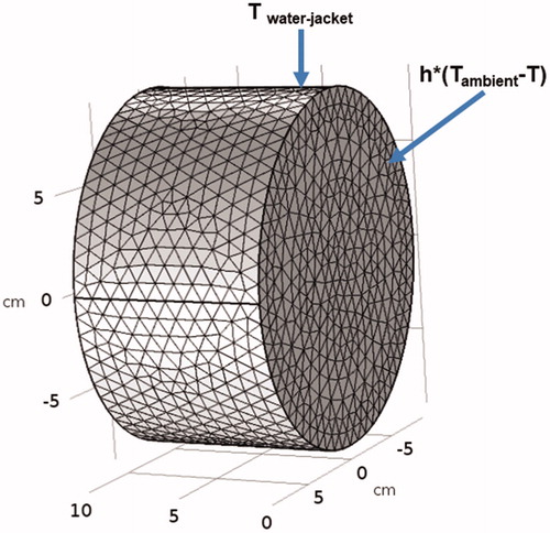
The two open surfaces in contact with ambient air were subjected to a convective heat flux boundary condition ():
(4)
(4)
where
is the ambient air temperature (20 °C) and
is the free convection heat transfer coefficient
The above equations are coupled with EquationEquation 2
(2)
(2) and were simultaneously solved using a commercially available finite element solver (COMSOL 5.3a, Burlington, MA, USA). Electrical properties were assumed to be independent of temperature. To make the computed temperature independent of the mesh and time step size, 43772 elements and a time step of 1 s were chosen based on a sensitivity analysis. AMF induced heating was modeled for duration of 20 min. The AMF distribution generated by the modified Maxwell coil and AMF tissue interaction with tissue equivalent homogeneous gel phantom were studied using simulations and experimental measurements.
Thermal simulations using a multilayer thermal regulatory model was used to compare the tissue heating due to the extrapolated human scale modified Maxwell coil and the commercial MFH®300F [Citation38] system. The heat transport mechanisms occurring in living tissues have been formulated using the bioheat equation (EquationEquation 2(2)
(2) ). A multi-layer cylindrical thermal regulatory model previously reported [Citation46] was used to compare the tissue heating caused by AMF distribution from an inhomogeneous (‘C-shape’) inductor, such as the MFH®300F [Citation38] and a uniform AMF (assuming a linear scaleup from the 20 cm modified Maxwell coil to a human size). AMF field distribution from MFH®300F was modeled using polynomial equation (EquationEquation 4
(4)
(4) in Reference Citation38). The parameters of the polynomial equation were selected to expose the center of the multi-layer cylindrical thermal regulatory model to AMF amplitude of ∼3.7 kA/m, near the Atkinson–Brezovich limit [Citation22,Citation23]. This results in AMF amplitude of 6–7 kAm at the superficial layers of the cylindrical thermal regulatory model. For the human scaled modified Maxwell coil, the multi-layer cylindrical thermal regulatory model uniform AMF amplitude 3.7 kA/m was used.
Results
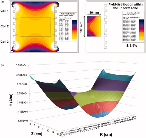
A three-piece Maxwell-type coil set was designed using Flux 2D FEA. Initial simulations were conducted using a single-turn coil to model initial parameters and constraints required to meet the desired specifications. Simulated magnetic field produced by the model single-turn coil is shown in . For the three piece coil set, turn dimensions were varied to achieve the desired magnetic field distribution (). The predicted magnetic field distribution is shown as axial cross-section in , and as a three-dimensional plot in . The individual turns were designed using copper sheets with brazed copper tubing to minimize power demand and reactive power. Field variability of ±3.5% was observed in the region of interest (radius 8 cm and length 10 cm; box at the center ). The parameters of the three-coil set and resulting magnetic field distribution are consistent with the single turn system represented in , which was optimized to produce a field using 1/3 of the total reactive power. Additionally, current, voltage and reactive power predicted through analytical calculations were in general agreement with finite element method (Flux 2D) results (Supplementary Material). Moreover, the analytical formulas provided approximate values to predict electrical circuit resistance (0.4 mΩ), inductance (0.12 μH) and capacitance for resonance (8.93 μF).
Figure 4. 2D Finite Element simulations of a three-piece induction coil set and measured magnetic field generated by the three-piece Maxwell-type induction system. (a) Computer simulation of predicted magnetic field strength distribution in a three-piece induction coil set. (b) Simulated magnetic field map for a three-piece induction coil set. (c) Measured AMF amplitude field map. (d) Measured AMF amplitude field map for 8.2 kA/m (rms) at center of the cylinder. Boxed area represents the area with ±10% in error margin.
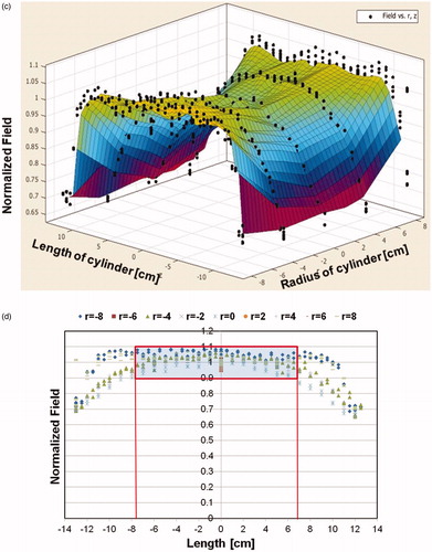
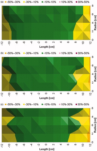
The prototype heat stations and coil sets are shown in . Measurements of magnetic field distribution were made using a magnetic field probe (), and with a solid cylinder bearing holes for placing the field probe (). Results from probe measurements of generated magnetic field amplitude at a setting of 8.2 kA/m (peak) in the coil center are shown in , at varying locations (radii and length) in the coil. A 2D representation is provided in showing field homogeneity within the desired volume. Measurements of field were consistent with those predicted by computational simulations, and field uniformity satisfied the design specification; validating the design process. Measurements of field uniformity (±10%) at multiple AMF amplitudes ranging from 7.5 kA/m(peak) to 15 kA/m(peak) are shown in . The measured field uniformity was observed in cylindrical volumes ≥2.7 × 103 cm3 for the AMF amplitudes under study. The cylindrical volume of the magnetic field uniformity decreased from 3.2 × 103 cm3 to 2.7 × 103 cm3 when the AMF amplitude increased from 7.5 kA/m(peak) to 15 kA/m(peak).
Figure 5. Measured magnetic field generated by Maxwell induction system is uniform. (a) Uniform magnetic field area (cylindrical volume of ∼3.2 × 103 cm3) of ±10% in error margin (in green) at 7.5 kA/m (rms). (b) Uniform magnetic field area (cylindrical volume of ∼2.9 × 103 cm3) of ±10% in error margin (in green) at 10 kA/m (rms). (c) Uniform magnetic field area (cylindrical volume of ∼2.7 × 103 cm3) of ±10% in error margin (in green) at 15 kA/m (rms).
To simulate the potential effects of eddy current heating on tissue exposed to the field, we inserted a gel phantom having tissue equivalent conductivity. Temperature probes placed on the radial axis along the diameter at 1 cm spacing provided a record of the distribution of power deposited during AMF exposure (). Temperature elevations of approximately 4 °C to 6 °C were observed at the outer edge of the gel phantom with exposure to AMF amplitude of 3 kA/m (). For radial locations, ≤4 cm temperature elevations were ≤1 °C.
Figure 6. Tests with gel phantoms demonstrate extent of nonspecific heating arising from eddy currents. (a) Schematic of the experimental setup of the tissue equivalent gel phantom exposed to an AMF amplitude of 3 kA/m (rms) generated by the three-piece Maxwell-type induction coil and cooled with water jacket at 20 °C for 20 min. Transient temperature measurements were carried out at six locations (denoted by ‘x’ in the figure) beginning at the gel center (r = 0) and at 1 cm increments toward the outer edge. (b) Temperatures measured in gel phantom with fiber optic probes when exposed to 3 kA/m field. Radial dependence of nonspecific heating in tissue mimicking gel phantom placed inside the circulating water jacket at room temperature is demonstrated. (c) 2D Temperature distribution at the center of the simulation geometry when exposed to an AMF amplitude of 3 kA/m (rms) at 150 kHz for 20 min. The FEA simulations of temperature distribution in gel phantom due to nonspecific heating arising from eddy currents predict similar trends as measured experimentally as shown in (b).
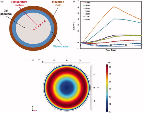
Thermal simulations predicted a radial dependence of the computed temperature rise () similar to the measured temperature rise observed in the gel phantom (). The cooling effect from the water jacket had a limited penetration ∼1–2 cm (). The maximum computed temperature rise of ∼6 °C was predicted closer to the outer edge of the gel, consistent with the experimentally measured temperature at r = 6 cm. The simple thermal model predicted similar trends to the experimentally measured heating due to eddy currents.
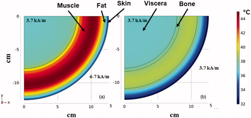
Simulations of temperature distribution resulting from exposure to an inhomogeneous field calculated using field parameters similar to those described for the MFH®300F demonstrate significantly higher eddy current heating of tissues to achieve a similar field amplitude at target depth of ∼12 cm. With an inhomogeneous field-emitting inductor, the surface of a patient is exposed to much higher AMF amplitudes because field intensity is non-uniform and high near the inductor surface leading to significantly higher total power deposition into the tissue. Superficial eddy current heating of tissues is more intense compared to uniform AMF (). The simulated heating from an inhomogeneous field inductor similar to the MFH®300F generates a maximum temperature of ∼45 °C () at the muscle-fat interface. On the other hand, for a similar target amplitude (∼3.7 kA/m) at the tumor the homogeneous AMF simulated for the human scale modified Maxwell coil generates a substantially lower maximum temperature <40 °C in the superficial layers ().
Figure 7. FEA simulations of temperature distribution in the multilayer cylindrical thermal regulatory model comparing nonspecific heating from nonuniform and uniform AMFs. Thermal distribution at the end of 20 min heating time at a fixed frequency of 150 kHz for (a) exposure to inhomogeneous fields as generated by MFH®300F with amplitude of ∼3.7 kA/m at target located ∼12 cm depth. (b) As in (a) but from uniform AMF from the human scale modified Maxwell coil.
Discussion
One approach for treating deep-seated tumors with MFH is to design coils that generate homogeneous AMFs having appropriate amplitude for large target volumes (∼103 cubic centimeters). AMFs can generate intense heating by hysteresis loss in magnetic materials; however, they can also deposit power via induced eddy currents in electrically conductive diamagnetic bodies such as human tissue (EquationEquation 1(1)
(1) ). Controlled, focal hysteresis heating and minimized induction heating of tissue is the desired outcome of MFH [Citation5,Citation20]. Over the past five decades various coil geometries for hyperthermia with ferromagnetic implants and magnetic nanoparticles have been tested. Inherent challenges encountered with MFH arising from the physics of low-frequency magnetic field interactions with tissues were identified early. In the first work published over 50 years ago, Gilchrist et al. [Citation52] accurately identified and described the challenges to translate this version of ‘nano-thermal medicine’ to the clinic [Citation4]. No heating experiments were conducted in live animals (dogs) because the authors believed their magnetic field coils were unsuited to produce the necessary field amplitudes for effective therapy. Since this early attempt, several advances in technology, engineering and magnetic nanostructured materials have provided new tools with which to develop MFH as a therapeutic modality [Citation3,Citation5].
Simple solenoids (sometimes called ‘air-core’ coils) have been a preferred choice for MFH because they are simple to produce, and they efficiently generate high peak-amplitude fields with limited stray fields extending outside the coil [Citation12,Citation13,Citation18–20,Citation25,Citation33,Citation34]. Simple solenoid coils, however produce a uniform magnetic field only in a limited volume within the coil, and non-uniform three-dimensional field gradients extending in both axial and transverse directions. Park et al. used a nine-turn solenoid to induce heating by eddy current losses in stainless-steel implants in rabbit livers [Citation53]. Stauffer et al. [Citation25,Citation33] designed and tested solenoids, including a double-layer reverse-wound solenoid to overcome field inhomogeneities in solenoids. This design also aimed to reduce the magnitude of electric fields generated between close windings of the solenoid, which can contribute to superficial heating. This electric field effect is a potential issue only for solenoids, and is not necessarily relevant for other geometries such as single-turn coils or Helmholtz pairs. Surface coils, such as spiral pancake coils [Citation12,Citation19,Citation34] deliver fields having amplitude that rapidly decays with distance normal to the coil plane. Such coils are able to provide sufficient field amplitude to generate effective heating for near-surface tumors (∼2 cm) [Citation12,Citation19,Citation54].
Solid core, i.e., solenoid wound around a material having high magnetic permeability (solid core), coils have also been explored with advanced development and validation in human clinical trials. Gneveckow et al. [Citation38] developed a clinical MFH therapy system (MFH®300F) consisting of a C-shaped high permeability ferrite core, around which two solenoid coils were wrapped. The patient is placed in the air gap of the core. The MFH®300F produces AMF intensities sufficient to generate therapeutic heating from magnetic material situated in target tissue located deep within a body (>5 cm). The device achieved the stated goal, but exposes the surface of patients to much higher field amplitudes because field intensity is non-uniform and high near the inductor surface. Thus, success comes with the cost that superficial eddy current heating of tissues may be more intense, and the non-uniform field reduces intensity at greater tissue depth (distance from inductor) (). The former constrains treatment to assure patient safety, while the latter affects thermal dosimetry and potency of treatment.
Loney coils are used to generate very uniform magnetic fields in a well-defined region within one (main) coil. Generally, Loney coils consist of a main coil and auxiliary so-called correcting, or shim, coils i.e., multiple solenoids having specific geometrical placement [Citation47]. Di Barba et al. modified the radii and axial separation of two coils, a main and a correcting coil, to minimize the magnetic field variation across a finite target region [Citation47,Citation55]. A more recent approach called ‘focused low-RF hyperthermia’ attempts to create a shielding effect with an external static magnetic field to minimize exposure of large volumes of tissue outside the target volume [Citation35]. A magnetic field free (weak field) region is created in the tumor (target) volume by using multiple (or array) DC coils and an AC coil(s) is used to project AMF to the target volume, while maintaining static magnetic field everywhere else.
Interstitial hyperthermia with magnetic materials offers the potential to deliver heat to a well-defined volume deep within a body that may otherwise present daunting challenges for other hyperthermia modalities [Citation1,Citation3–5]. Combining magnetic materials with low frequency (50–200 kHz) AMFs also provides an opportunity to perform multiple treatment sessions from a single injection or placement of magnetic material [Citation5,Citation17,Citation22,Citation24]. Providing a predictable thermal dose for prescriptive treatment depends, in part upon the AMF uniformity. Helmholtz coils generate uniform fields but they require high reactive power and they typically generate significant stray fields, limiting their practical utility for many applications [Citation12,Citation25,Citation33,Citation34]. To overcome these challenges, we explored a design of a system comprising modular coil components that separate the required reactive power into manageable values and when combined are able to generate a uniform field in a large volume (≥3.0 × 10³ cubic centimeters). Additional analytical calculations were helpful to estimate predicted electrical parameters and the results of these were compared with simulation results (Supplementary Material). While there was general agreement, some deviation was noted largely due to estimates of losses in electrical components. This highlights the potential complexities involved to develop high Q resonance circuits to deliver high current, emphasizing that simplifying assumptions in calculations should be avoided. It also emphasizes the need to measure field produced in coils, regardless of their geometry, rather than relying only on analytical calculations.
Prior efforts explored induction coil designs to generate AMFs for much smaller volumes (10 to 102 cm3) [Citation20,Citation33–35]. These requirements placed less demand on commercial components because the required power rarely exceeded 10 kilowatts, with reactive power demands <1 MVAR. To generate homogeneous AMFs for large target volumes (>∼103 cubic centimeters, or more) the reactive power may easily exceed 100 MVAR for higher magnetic field amplitudes. The developed prototype is based upon a set of heat stations connected in parallel receiving power from a common supply, and each had its own induction coil to minimize total reactive power. Thus, the developed system resolved relatively high reactive power demands to ∼12 MVAR with these innovations [Citation51].
With each heat station having its own induction coil, risks associated with insufficient electrical contact on the high current output leads arising from differences in mechanical tolerance among the components were reduced as the induction coils were magnetically coupled. Mutual inductance among the coils balanced voltage variations between pairs of inductors, thus compensating for inherent variations in input voltage drops associated with different capacitance values, inherently required to compensate for central versus the outer coils.
The developed system comprising three independent coil loops produced a homogeneous (±10%) AMF amplitude up to 35 kA/m in a cylindrical volume of ∼3000 cm3 at a frequency of approximately 150 kHz with low electric field strength, while minimizing reactive power and demands on the power supply (). While it is recognized that clinically relevant field amplitudes at this frequency are much lower, i.e., ≤4 kA/m for a human torso [Citation22,Citation23], achieving stable and homogeneous operation at much higher field amplitudes demonstrates the robust stability of this design in the scale prototype.
The developed prototype was designed to be scalable to a human-sized system (∼60 cm diameter). The current scale was intended to provide a system suitable for validation with both gel phantoms and larger animal studies sufficient to challenge its performance and to validate our hypothesis that an inductor producing a homogeneous flux density AMF could provide reliable MFH heat treatments for tumors located deep within a body. Studies with larger animal models are underway and incomplete; however, the presented measurements of field distribution and eddy current heating in gel phantoms demonstrate agreement with simulations, validating the latter for further optimization and for comparisons with other inductor geometries. Using these simulations, we have compared differences of eddy current heating between homogeneous (e.g., the Maxwell inductor) and inhomogenous (e.g., MFH®300F [Citation38]) AMFs that result if attempting to treat a tumor located ∼10 cm from the surface at a field amplitude of ∼4 kA/m. The simulations predict that homogeneous AMF significantly reduces tissue temperatures near the surface, while still maintaining constant field amplitude at the target. This potentially simplifies treatment planning compared MFH®300F, and enables treatment with much less risk of normal tissue damage. On the other hand, inductors relying on inhomogeneous fields, such as the MFH®300F expose the surface of patients to much higher AMF amplitudes, generating more volumetric eddy current power deposition, in order to achieve similar therapeutic field amplitude at a distance for heating targets located deep in the body (Supplementary Material and ).
Eddy current tissue heating has long been recognized as a limitation for MFH and other RF-based modalities that expose large volumes of a body to low frequency RF fields, yet there seems to have been relatively little effort devoted to developing strategies to compensate or avoid the issue [Citation10,Citation11,Citation22,Citation23,Citation30,Citation37,Citation55]. Another challenge of exposing large volumes of a body to AMF for MFH arises from stimulating nanoparticles deposited in non-targeted tissues and organs, i.e., liver [Citation41]. Inadvertent heating of nanoparticles accumulating in off-target healthy organs carries potential to increase treatment-related toxicities, particularly if high heating nanoparticle formulations are used. One approach to address both issues has been to use multiple coils having phase differences adjusted among them to reduce/amplify the AMF amplitude in specific tissue regions [Citation35]. Such approaches offer promise because they can enhance heat output of nanoparticles in targeted tissues, while reducing both eddy current and hysteresis heating in off-target tissues. On the other hand, such device configurations place demands on control and power systems increasing cost and complexity of equipment. Another approach is to modulate power and/or amplitude of the AMF in such a manner to enhance physical and biological heat transfer processes to moderate off-target heating without sacrificing much on-target heating [Citation7,Citation36,Citation56,Citation57]. Recently, the use of single, or only few turn coils, has been developed with length/diameter ratios between 0.25 and 0.75 to minimize nonspecific heating and limit illumination of particles outside the target regions while still providing a relatively large volume of uniform magnetic field [Citation58]. This system was tested on a full sized brain phantom filled with agar gel at clinically relevant fields (<6 kA/m at 133 kHz) in combination with a balloon filled with magnetic nanoparticles and demonstrated the capability to deliver a volumetric power density of 0.5 W/mL for treatment of surgically resected tumors [Citation59]. Wider clinical acceptance of MFH will likely require significant efforts to develop robust procedures for reducing the nonspecific eddy current and off-target hysteresis heating.
Conclusions
An induction coil apparatus comprising three independent loops, i.e., Maxwell-type that operates with power demand and reactive power capable to generate clinically relevant uniform AMF amplitudes in a cylindrical volume ≥ 2.7 × 103 cm3 at ∼150 kHz was developed. This design improves upon the performance of simple solenoid and Helmholtz coils by providing homogeneous flux density fields within a large volume while minimizing demands on power and stray fields. For MFH, a homogeneous flux density field provides advantages to reduce nanoparticle heating heterogeneity, and offers potential to decrease overall nonspecific eddy current heating, but at the expense of increased potential for off-target hysteresis heating. Further research is needed to develop methods to mitigate the nonspecific and off-target heating to enable wider clinical adoption of MFH.
Supplemental Material
Download PDF (377 KB)Disclosure statement
J.J., V.N., C.Y. and R.C.G. are/were employees of AMF Life Systems, Inc. at the time the work described was performed. R.I. is an inventor on nanoparticle patents, and all these patents are assigned to either The Johns Hopkins University or Aduro BioTech, Inc. R.I. consults for Imagion Biosystems, a company developing imaging with magnetic iron oxide nanoparticles. The contents of this article are solely the responsibility of the authors and do not necessarily represent the official view of the Johns Hopkins or NIH.
Additional information
Funding
References
- Johannsen M, Gneveckow U, Thiesen B, et al. Thermotherapy of prostate cancer using magnetic nanoparticles: feasibility, imaging, and three-dimensional temperature distribution. Eur Urol. 2007;52(6):1653–1662.
- Marchal S, Hor AE, Millard M, et al. Anticancer drug delivery: an update on clinically applied nanotherapeutics. Drugs. 2015;75(14):1601–1611.
- Kozissnik B, Bohorquez AC, Dobson J, et al. Magnetic fluid hyperthermia: advances, challenges, and opportunity. Int J Hyperthermia. 2013;29(8):706–714.
- Ivkov R. Magnetic nanoparticle hyperthermia: a new frontier in biology and medicine? Int J Hyperthermia. 2013;29(8):703–705.
- Dennis CL, Ivkov R. Physics of heat generation using magnetic nanoparticles for hyperthermia. Int J Hyperthermia. 2013;29(8):715–729.
- Dennis CL, Jackson AJ, Borchers JA, et al. Nearly complete regression of tumors via collective behavior of magnetic nanoparticles in hyperthermia. Nanotechnology. 2009;20(39):395103.
- Attaluri A, Kandala SK, Zhou H, et al. Magnetic nanoparticle hyperthermia enhances radiation therapy: a study in mouse models of human prostate cancer. Int J Hyperthermia. 2015;31(4):359–374.
- Attaluri A, Seshadri M, Mirpour S, et al. Image-guided thermal therapy with a dual-contrast magnetic nanoparticle formulation: a feasibility study. Int J Hyperthermia. 2016;32(5):543–557.
- Oliveira TR, Stauffer PR, Lee C-T, et al. Magnetic fluid hyperthermia for bladder cancer: a preclinical dosimetry study. Int. J. Hyperthermia. 2013;29(8):835–844.
- Barnes FS, Greenebaum B. Biological and medical aspects of electromagnetic fields. Boca Raton (FL): CRC Press, Taylor & Francis Group; 2006.
- Greenebaum B, Barnes FS. Bioengineering and biophysical aspects of electromagnetic fields. Boca Raton (FL): CRC Press, Taylor & Francis Group; 2006.
- Nemkov V, Ruffini R, Goldstein R, et al. Magnetic field generating inductor for cancer hyperthermia research. Compel. 2011;30(5):1626–1636.
- Bordelon D, Goldstein R, Nemkov V, et al. Modified solenoid coil that efficiently produces high amplitude AC magnetic fields with enhanced uniformity for biomedical applications. IEEE Trans Magn. 2012;48(1):47–52.
- Baronzio GF, Hager ED. Hyperthermia in cancer treatment: a primer. New York (NY): Landes Biosciences and Springer Science+Business Media, LLC; 2008.
- Solazzo SA, Liu Z, Lobo SM, et al. Radiofrequency ablation: importance of background tissue electrical conductivity – An agar phantom and computer modeling study. Radiology. 2005;236(2):495–502.
- Maier-Hauff K, Rothe R, Scholz R, et al. Intracranial thermotherapy using magnetic nanoparticles combined with external beam radiotherapy: results of a feasibility study on patients with glioblastoma multiforme. J Neurooncol. 2007;81(1):53–60.
- Maier-Hauff K, Ulrich F, Nestler D, et al. Efficacy and safety of intratumoral thermotherapy using magnetic iron-oxide nanoparticles combined with external beam radiotherapy on patients with recurrent glioblastoma multiforme. J Neurooncol. 2011;103(2):317–324.
- Thompson MT. Simple models and measurements of magnetically induced heating effects in ferromagnetic fluids. IEEE Trans Magn. 1998;34(5):3755–3764.
- Dughiero F, Corazza S. Numerical simulation of thermal deposition with induction heating used for oncological hyperthermia treatment. Med Biol Eng Comput. 2005;43(1):40–46.
- Candeo A, Dughiero F. Numerical FEM models for the planning of magnetic induction hyperthermia treatments with nanoparticles. IEEE Trans Magn. 2009;45(3):1658–1661.
- Dennis CL, Krycka KL, Borchers JA, et al. Internal magnetic structure of nanoparticles dominates time-dependent relaxation processes in a magnetic field. Adv Funct Mater. 2015;25(27):4300–4311.
- Atkinson WJ, Brezovich IA, Chakraborty DP. Usable frequencies in hyperthermia with thermal seeds. IEEE Trans Biomed Eng. 1984;31(1):70–75.
- Nyenhuis JA, Mouchawar GA, Bourland JD, et al. Energy considerations in the magnetic (eddy-current) stimulation of tissues. IEEE Trans Magn. 1991;27(1):680–687.
- Wust P, Gneveckow U, Johannsen M, et al. Magnetic nanoparticles for interstitial thermotherapy–feasibility, tolerance and achieved temperatures. Int J Hyperthermia. 2006;22(8):673–685.
- Stauffer PR, Cetas TC, Jones RC. Magnetic induction heating of ferromagnetic implants for inducing localized hyperthermia in deep-seated tumours. IEEE Trans Biomed Eng. 1984;31:235–251.
- Lin JC, Bernardi P. Computational methods for predicting field intensity and temperature change. In: Barnes FS, Greenebaum B, editors. Bioengineering and biophysical aspects of electromagnetic fields. 3rd ed. Boca Raton (FL): CRC Press, Taylor & Francis Group; 2007. p. 293–380.
- Liu F, Zhao H, Crozier S. On the induced electric field gradients in the human body for magnetic stimulation by gradient coils in MRI. IEEE Trans Biomed Eng. 2003;50(7):804–815.
- Wang Q, Deng ZS, Liu J. Theoretical evaluations of magnetic nanoparticle-enhanced heating on tumor embedded with large blood vessels during hyperthermia. J Nanopart Res. 2012;14:974–984.
- Szasz A, Szasz O, Szasz N. 2006 Physical background and technical realizations of hyperthermia. In: Baronzio GF, Hager ED, editors. Hyperthermia in cancer treatment: a primer. New York (NY): Landes Bioscience and Springer; 2006. p. 27–52.
- Black DR. Thermoregulation in the presence of radio frequency fields. In Barnes FS, Greenebaum B, eds. Biological and medical aspects of electromagnetic fields. 3rd ed. Boca Raton (FL): CRC Press, Taylor & Francis Group; 2006. p. 215–226.
- Cerchiari U. Hyperthermia, physics, vector potential, electromagnetic heating: a primer. In Baronzio GF, Hager ED eds. Hyperthermia in cancer treatment: a primer. New York (NY): Landes Bioscience and Springer; 2006. p. 3–18.
- Polk C. Introduction. In Barnes FS, Greenebaum B, editors. Biological and medical aspects of electromagnetic fields. 3rd ed. Boca Raton (FL): CRC Press, Taylor & Francis Group; 2006. p. xiii–xxvi.
- Stauffer PR, Sneed PK, Hashemi H, et al. Practical induction heating coil designs for clinical hyperthermia with ferromagnetic implants. IEEE Trans Biomed Eng. 1994;41(1):17–28.
- Ellinger DC, Chute FS, Vermeulen FE. Evaluation of a semi-cylindrical solenoid as an applicator for radio-frequency hyperthermia. IEEE Trans Biomed Eng. 1989;36(10):987–994.
- Tasci TO, Vargel I, Arat A, et al. Focused RF hyperthermia using magnetic fluids. Med Phys. 2009;36(5):1906–1912.
- Ivkov R, DeNardo SJ, Daum W, et al. Application of high amplitude alternating magnetic fields for heat induction of nanoparticles localized in cancer. Clin Cancer Res. 2005;11(19):7093s–7103s.
- Trakic A, Liu F, Crozier S. Transient temperature rise in a mouse due to low-frequency regional hyperthermia. Phys Med Biol. 2006;51(7):1673–1691.
- Gneveckow U, Jordan A, Scholz R, et al. Description and characterization of the novel hyperthermia- and thermoablation-system MFH®300F for clinical magnetic fluid hyperthermia. Med Phys. 2004;31(6):1444–1451.
- Jordan A, Wust P, Scholz R, et al. Magnetic fluid hyperthermia (MFH). In: Hafeli U, Zborowski M, Schutt W, editors. Scientific and clinical applications of magnetic carriers. New York (NY): Plenum Press; 1997. p. 569–595.
- Kumar A, Attaluri A, Mallipudi R, et al. Method to reduce non-specific tissue heating of small animals in solenoid coils. Int J Hyperthermia. 2013;29(2):106–120.
- Kut C, Zhang Y, Hedayati M, et al. Preliminary study of injury from heating systemically delivered, nontargeted dextran-superparamagnetic iron oxide nanoparticles in mice. Nanomedicine. 2012;7(11):1697–1711.
- Dewhirst MW, Jones E, Samulski T, et al. Hyperthermia. In: Kufe DW, Pollock RE, Weichselbaum RE, Bast RC, Gansler TS, eds. Cancer medicine. 6th ed. Hamilton (ON): BC Decker; 2003. p. 623–636.
- Dewhirst MW, Viglianti BL, Lora-Michiels M, et al. Basic principles of thermal dosimetry and thermal thresholds for tissue damage from hyperthermia. Int J Hyperthermia. 2003;19(3):267–294.
- Maxwell JC, Thompson JJ. A treatise on electricity and magnetism: pt. III magnetism. IV electromagnetism. London, UK: Clarendon Press for the University of Oxford; 1892.
- Cao Q, Han X, Zhang B, et al. Analysis and optimal design of magnetic navigation system using Helmholtz and Maxwell coils. IEEE Trans Appl Supercon. 2011;322(3):4401504.
- Fiala D, Lomas KJ, Stohrer M. A computer model of human thermoregulation for a wide range of environmental conditions: the passive system. J Appl Physiol. 1999;87(5):1957–1972.
- Di Barba P, Dughiero F, Sieni E. Magnetic field synthesis in the design of inductors for magnetic fluid hyperthermia. IEEE Trans Magn. 2010;46(8):2931–2934.
- Jeon S, Jang G, Choi H, et al. Magnetic navigation system with gradient and uniform saddle coils for the wireless manipulation of micro-robots in human blood vessels. IEEE Trans Magn. 2010;46(6):1943–1946.
- Ha YH, Han BH, Lee SY. Magnetic propulsion of a magnetic device using three square-Helmholtz coils and a square-Maxwell coil. Med Biol Eng Comput. 2010;48(2):139–145.
- Byun JK, Choi K, Roh HS, et al. Optimal design procedure for a practical induction heating cooker. IEEE Trans Magn. 2000;36(4):1390–1393.
- Goldstein R, Nemkov V, inventors; AMF Life Systems, LLC, assignee. Generating strong magnetic fields at low radio frequencies in larger volumes. WO2018009542A1. 2018 Jan 11.
- Gilchrist RK, Medal R, Shorey WD, et al. Selective inductive heating of lymph nodes. Ann Surg. 1957;146(4):596–606.
- Park BH, Koo BS, Kim YK, et al. The induction of hyperthermia in rabbit liver by means of duplex stainless steel thermoseeds. Korean J Radiol. 2002;3(2):98–104.
- Stigliano RV, Shubitidze F, Petryk JD, et al. Mitigation of eddy current heating during magnetic nanoparticle hyperthermia therapy. Int J Hyperthermia. 2016;32(7):735–738.
- DiBarba P, Dughiero F, Trevisan F. Optimization of the Loney's solenoid through quasi-analytical strategies: a benchmark problem reconsidered. IEEE Trans Magn. 1997;33(2):1864–1867.
- Soetaert F, Dupré L, Ivkov R, et al. Computational evaluation of amplitude modulation for enhanced magnetic nanoparticle hyperthermia. Biomed Engin/Biomedizinische Technik. 2015;60:491–504.
- Kandala SK, Liapi E, Whitcomb LL, et al. Temperature-controlled power modulation compensates for heterogeneous nanoparticle distributions: a computational optimization analysis for magnetic hyperthermia. Int J Hyperthermia. 2019;36(1):115–129.
- Goldstein R, inventor; AMF Life Systems, LLC, assignee. Induction coil for low radiofrequency applications in a human head. US Patent 10,286,223 B2. 2019 May 14.
- Stauffer P, Rodrigues DB, Goldstein R, et al. Dual modality implant for simultaneous magnetic nanoparticle heating and brachytherapy treatment of tumor resection cavities in brain. In: 2018 IEEE/MTT-S International Microwave Symposium – IMS. New York, NY: IEEE, 2018. p. 1285–1288.