
 ?Mathematical formulae have been encoded as MathML and are displayed in this HTML version using MathJax in order to improve their display. Uncheck the box to turn MathJax off. This feature requires Javascript. Click on a formula to zoom.
Abstract
Background
Trans-cranial MR guided focused ultrasound (tcMRgFUS) ablation targets are <5mm from critical neurological structures, creating a need for improved MR imaging and thermometry. The purpose of this study was to evaluate the performance of a dual-channel radiofrequency receive-only head coil designed specifically for integrated use in tcMRgFUS.
Methods
Imaging used a 3 T MRI and the ExAblate Neuro System (INSIGHTEC Inc., Israel). Sensitivity maps determined receive-only coil uniformity. The head coil was compared to the volume body coil at the level of the thalamus using 1) T2-weighted imaging and 2) multi-echo MR thermometry of volunteers in the transducer helmet. Thermal sonications (40 W, 24s) were acquired in a heating phantom. Thermal maps in were constructed to evaluate temperature uncertainty, focal heating, and temperature evolution.
Results
The normalized signal intensity showed up to a 35% variation. On T2wFSE images the SNR with the head coil is improved by 4x in the axial plane, and 3x in sagittal and coronal planes. The head coil provided better visualization of the thalamus and globus pallidus (axial), and of the anterior/posterior commissure, and brain stem/cerebellum (sagittal) compared to the body coil. MR thermometry showed a 4x gain in SNR in the thalamus. Thermometry showed a preserved focal spot with 20 °C temperature rise. The average temperature uncertainty (mean ± std) was reduced from σT = 0.96 °C ± 0.55 °C for the body coil to σT = 0.41 °C ± 0.24 °C for the head coil.
Conclusions
Greater SNR from the dual-channel head coil provides access to better treatment day visualization for treatment planning and higher precision intra-operative thermometry.
Introduction
Transcranial magnetic resonance guided high intensity focused ultrasound (tcMRgFUS) is an incisionless method used for thermal ablation that is currently being used to treat essential tremor (ET), Parkinson’s disease, obsessive-compulsive disorder, and neuropathic pain [Citation1–6]. Non-thermal uses of the technology are being investigated such as opening of the blood brain barrier or neuromodulation [Citation7–10].
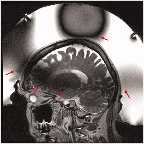
The quality of MR imaging plays a critical role in transcranial MR guided focused ultrasound. With only 2−5 mm separating the target from adjacent critical neurological structures, precise targeting of the lesion is imperative. In addition, accurate, precise MR thermometry is also vital as it provides essential intra-operative feedback on both treatment efficacy and safety. Due to the large hemispherical transducer array, MR imaging for tcMRgFUS at 3 Tesla has been limited to use of the magnet bore body coil. Furthermore, the presence of the transducer array, comprised of piezoelectric elements, acoustic matching layers, and front-end electronics, and water inside the volume body coil induce B0 and B1 field inhomogeneities that result in reduced overall image quality and areas of signal loss. The inhomogeneity of the B1 field produces spatially varying flip angles throughout the head and can reduce transmit/receive efficiency of the body coil by acting as a radiofrequency shield and supporting standing waves. shows a typical example using a T2-weighted Fast Spin Echo (FSE) sequence, used for planning in an 87-year-old patient treated for essential tremor by targeting the ventral intermediate nucleus of the thalamus. Dark areas of signal loss are observed in the anterior superior portion of the head, which asymmetrically continue through the thalamus to the posterior inferior portion of the head, and at the crown (, red arrows). In addition, the relatively low signal-to-noise ratio (SNR) of the body coil and lack of acceleration capabilities are a large hindrance to a) the spatial resolution that can be achieved, b) the available sequences for imaging, and c) the temporal resolution of thermometry. Specialized imaging coils designed for MR guided focused ultrasound have been explored both in pre-clinical applications and in human applications outside of the head [Citation11–13]. Although a split quadrature volume transmit/receive head coil and flexible printed receive coils have showed promising results in phantoms inside the hemisphere transducer array, no results in humans have been presented [Citation14,Citation15].
Figure 1. Transcranial MR guided focused ultrasound of an 87-year-old woman with essential tremor. Sagittal T2 weighted Fast Spin Echo (T2wFSE) treatment planning image of the brain acquired with the volume body coil shows the characteristic spatially varying signal loss through the thalamus and vertex (red arrows) due to the transducer array and water bath.
As more neurological applications are investigated using tcMRgFUS, there is a need for local coils to improve image quality and ensure adequate reception inside the transducer. Improved image quality may allow better visualization of anatomical brain features used for targeting, increase temporal resolution and spatial precision in real time temperature monitoring, reduce the total scan and treatment time, and allow use of new MR scans that are currently not available intra-operatively during tcMRgFUS treatments.
The purpose of this study was to evaluate the improved imaging performance provided by a two-channel radiofrequency (RF) receive-only head coil, developed by INSIGHTEC (Haifa, Israel) and designed specifically for use in transcranial MR guided focused ultrasound with the ExAblate Neuro system at 3 Tesla.
Materials and methods
Imaging was performed using a 3 T MRI scanner (MR750, GE Healthcare, Waukesha, WI) paired with the ExAblate Neuro System (INSIGHTEC, Inc, Haifa, Israel). The transcranial MRgFUS system consists of a 30 cm diameter, hemispheric, 1024-element phased array transducer operating at 650 kHz for ablation. The transducer helmet is integrated into an MRI table. All analysis was performed using MATLAB (The Mathworks, Inc., Natick, MA, USA).
Coil design
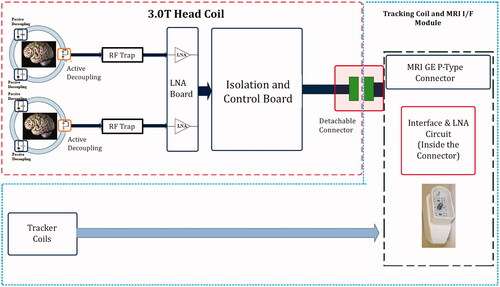
The head coil consisted of a 15.5 cm diameter receive-only dual-loop design. It was tuned for use at 3 T using a network analyzer. The coil was comprised of two flexible, identical loops that reside on either side of the patient’s head, by the ears (). The coils were covered by a silicone casing to render them waterproof and maintain low acoustic path attenuation. The coil is decoupled from the B1 transmit field by RF blocking circuits located on each of the coil elements. The RF blocking is achieved through a parallel resonance circuit at the system frequency (127.7 MHz), during transmission. The circuit imposes high impedance (>1 KOhm) on the coil loop, blocking the current flow in the coil due to the induced B1 transmitted field by the body coil. Coil element isolation is achieved by low noise amplifier circuits (LNA) with low input impedance. An isolation and control board are used to provide control signals to the LNA and interface with the connector. A schematic of the coil design is given in .
Figure 2. Dual channel RF head coil (red arrows) for transcranial MR guided focused ultrasound. The head coil is encased in a silicone membrane and integrated into the membrane that contains the coupling water inside the transducer. In this picture, the membrane and coil are shown surrounding a phantom that is held inside the transducer through a frame. In humans, the loop coils surround each ear next to a stereotactic head frame and extend into the water bath.
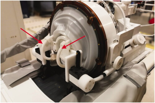
Figure 3. tcMRgFUS receive-only head coil schematic. Coil elements are decoupled using passive circuits that are switched on and off during transmission or reception. The signal from each coil loop passes through a dedicated low noise amplifier (LNA). RF traps are used to attenuate cable shield currents. Tracker coils used during treatment to locate the transducer coordinates are also integrated into the coil connector module.
Coil testing
Using a large spherical imaging phantom (16.8 cm diameter), sensitivity maps were constructed to determine receive-only coil performance and uniformity. For receive sensitivity maps only, B1 mapping was used to correct the transmit field due to the presence of the transducer. The head coil was then tested in two main areas: 1) image quality relevant to in-treatment planning and 2) image quality relevant to treatment monitoring through MR thermometry performance.
In vivo imaging
Images were acquired in two separate sessions in the membrane/water/transducer setup, one with the coil present and turned on, and one with a membrane with no head coil present (using the body magnet coil for transmit and receive). Volunteers wore swim caps in both sessions.
Images were acquired using a Fast Spin Echo (FSE) sequence (TE/TR = 100 ms/4600 ms, FOV = 24 cm, ST = 2 mm, ETL = 16, BW = 31 KHz, NEX = 1, Matrix Size = 320 × 256). B1 maps were acquired with the spherical phantom using the same setup as the volunteers (), and used a Bloch–Seigart phase shift approach [Citation16]. Based on B1 maps, the transmit gain was set to 180 (18 dB) to maximize signal in the area of dropout, particularly in the thalamus and was used for all imaging, with and without the head coil. Images were acquired in axial, sagittal, and coronal planes in volunteers. Three sets of images with and without the head coil were used in the analysis. Head coil image sets used data from volunteers 1, 2, and 3, and body coil image sets used data from volunteers 1, 2, and 4. Signal to noise ratio (SNR) was calculated by dividing the mean intensity of signal within the thalamic region by the standard deviation of a region of background noise, outside of the transducer.
In vivo thermometry
Thermometry images with and without the head coil were acquired in healthy volunteers using a multi-echo 2DFT gradient recalled echo sequence (TE = (3.2, 7.9, 12.6, 17.2, 22) ms, TR = 28 ms, FOV = 28 cm, ST = 3 mm, FA = 30, BW = 71 KHz, Matrix Size = 256 × 128). SNR was compared in the axial plane using the second echo magnitude image, ensuring steady state and cessation of water motion. To calculate a thermal map, complex phase difference images from pre-heating baseline ϕ(i,j), were calculated for each coil and for each echo. To account for phase wrap accrual of long echo times, phase unwrapping was applied to difference images in which the echo times > 10 ms. Echo combination used magnitude image and echo time weighting following:
(1)
(1)
where Te(n) = Te1, Te2,….TeN, are the sequence echo times, and Sm is the signal of the corresponding magnitude image. Further, phase difference images were converted to temperature maps by:
(2)
(2)
where γ is the gyromagnetic ratio, α = −0.01 ppm/°C is the PRF change coefficient for aqueous tissue, B0 is the main magnetic field strength. Temperature uncertainty was measured for each voxel by taking the standard deviation across time of the temperature maps for an axial slice in the brain. Average temperature uncertainty was then computed as the spatial average across the brain excluding the skull and water bath.
Thermometry during heating
The thermometry capability of the coil during heating was tested in a focused ultrasound phantom. The phantom was surrounded by a water bath inside the transducer array. Heating sonications (40 W, 24 s) were imaged using a single-echo 2DFT GRE thermometry sequence (TE/TR = 12 ms/26 ms, FOV = 28 cm, ST = 3 mm, FA = 25, BW = 11 KHz, Matrix Size = 256 × 128). Sonications were repeated and monitored in all three image planes. Since the upper portion of the coil occludes part of the ultrasound beam path, thermal maps were used to verify focal heating in the presence of the coil. Temperature evolution at the focal hotspot was plotted against time. To quantify potential phase drift contributions not related to heating, phase variation within an ROI inside the phantom but away from the heated region was used.
Results
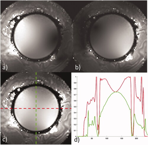
The corrected B1 maps show the spatial sensitivity of each coil separately, followed by the combined image in a large spherical phantom, given in . Combined imaging shows the signal uniformity across the phantom with a 25% variation in normalized signal intensity in the horizontal, or ear-to-ear direction, and a 25% reduction in maximum intensity as well as 35% variation in the anterior – posterior direction ().
Figure 4. Receive sensitivity maps of the head coil corrected for B1 in a spherical phantom for (a) channel 1, (b) channel 2, and (c) combined. The horizontal (red) and vertical (green) profiles through the combined image show a normalized signal intensity variation of 25% across the horizontal and 35% variation across the vertical center of the phantom.
In vivo imaging
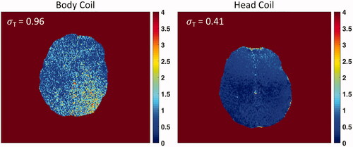
shows the comparison of planning images in axial, sagittal and coronal planes in a volunteer. Observational improvement with the head coil present can be seen by better visualization of the thalamus and globus pallidus on axial images, spatially varying improvement of grey/white matter differentiation, and greater detail of areas by the anterior and posterior commissures (AC/PC), brain stem, and cerebellum on sagittal images. Image quality differences in the magnitude of one echo (TE = 7.9 ms) of a multiecho thermometry sequence for volunteer 1 and 2 in the axial plane are shown in . A quantitative comparison of mean SNR across volunteers with and without the head coil is given for each scan plane (). Mean SNR was normalized to the maximum SNR across volunteers for each respective sequence type. In the area of the thalamus (), the SNR with the head coil is improved by 4x in the axial plane, 3x in both the sagittal and coronal planes on planning images. MR thermometry magnitude imaging showed a 4x improvement in the thalamus (). The average spatial temperature uncertainty across the brain was σT = 0.96 °C ± 0.55 °C for the volume body coil and σT = 0.41 °C ± 0.24 °C for the head coil. The temperature uncertainty map also showed improved spatial uniformity using the tcMRgFUS head coil ().
Figure 5. Comparison of image quality of T2wFSE treatment planning images in one volunteer without and with the tcMRgFUS head coil in the transducer water bath treatment setup. Head coil images provide greater detail of the thalamus, globus pallidus and subthalamic nucleus on axial images (orange arrows), and the anterior/posterior commissure (AC/PC), brain stem, and cerebellum on sagittal images.
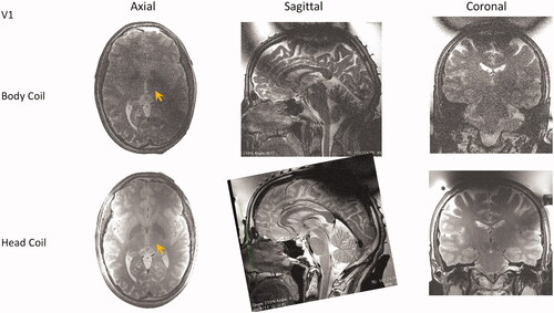
Figure 6. Comparison of image quality of GRE thermometry magnitude images in two volunteers without (a, b) and with (c, d) the tcMRgFUS head coil in the transducer water bath treatment setup.
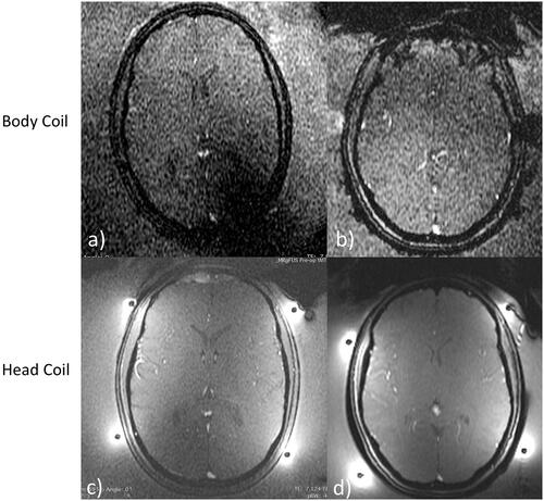
Figure 7. Comparison of mean SNR measured in the thalamus (a, green circle) using volume body coil or head coil. (b) Comparison using T2wFSE planning images is shown in 3 planes, and for thermometry images in the axial plane. Mean SNR was normalized to the maximum SNR across volunteers for each respective sequence type. Data are mean SNR ± standard deviation. For T2wFSE SNRnorm = 0.20 ± 0.05, 0.26 ± 0.03, and 0.25 ± 0.05 for the volume body coil, and SNRnorm = 0.95 ± 0.20, 1 ± 0.38, 0.85 ± 0.10 for the head coil, in the axial, sagittal, and coronal planes, respectively. For the thermometry sequence SNRnorm = 0.23 ± 0.04 for the volume body coil and SNRnorm = 1 ± 0.42 for the head coil.
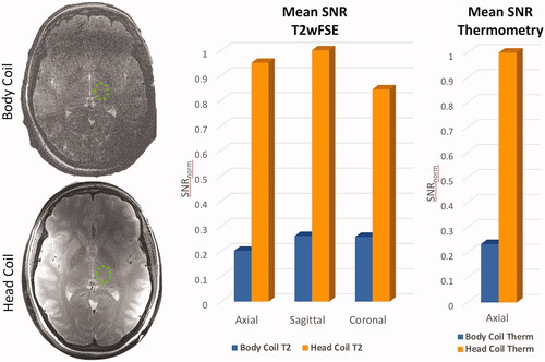
Figure 8. Temperature uncertainty in the brains of two volunteers using the volume body coil (left) and tcMRgFUS head coil (right). The σT is calculated as the spatial average of the standard deviation across the brain. Uniformity and σT is improved using the head coil (Body Coil σT = 0.96 °C ± 0.55 °C, and Head Coil σT = 0.41 °C ± 0.24 °C).
Thermometry during heating
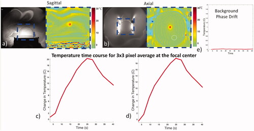
Temperature evolution was represented by the average of a 3 × 3 pixel region at the focal center in separate sonications imaged in axial and sagittal planes (). The heating curve mirrors the application of energy and decays exponentially with termination of the energy, as expected. The background phase variation and drift, monitored in a region of interest outside the focus but within the phantom, showed minimal drift and did not exceed 0.01 °C during the time course.
Figure 9. Coil performance during thermal heating. Magnitude (a, b left) and combined phase difference temperature maps (a, b right) for sonications in the sagittal and axial planes. Heating is restricted to the focus and follows a typical heating rise-decay curve (c, d). Minimal background phase variation was observed using an ROI away from the focal spot (white circle) over time (e).
Discussion
A custom-built dual loop receive-only coil was designed and tested in the transcranial MR guided focused ultrasound ExAblate Neuro system in healthy volunteers at 3 T. The coil design was chosen to improve both planning sequence image quality and intra-operative thermometry.
The fourfold improvement in SNR using the head coil versus the volume body coil and improved structural differentiation across the brain can be easily appreciated from all three image planes for planning images across volunteers. Although SNR is improved, the inhomogeneity of the B1 transmit field is unchanged; therefore, an area of marked signal loss remains in the most superior portion of the skull. MR thermometry magnitude images also showed a 4x SNR improvement, allowing for improved thermal precision. The axial plane saw the largest improvement in SNR. This may be due to the asymmetric signal loss at the level of the AC/PC plane, resulting in particularly low SNR around the thalamus using the volume body coil. In patient treatment protocols, T2wFSE planning sequences utilize additional 2–4 averages and reduced slice thickness to improve image quality at the cost of scan time. While the body coil images in this study are not optimized for SNR, this comparison presents identical sequence parameters for volunteers without the coil versus volunteers with the coil, thus, preserving the relative measurements. An even greater absolute SNR may be achieved in the patient setting.
An important element of any coil within the focused ultrasound beam path is potential interference with the beam focus. In this study, heating experiments in phantoms in axial and sagittal planes showed a preserved highly focal spot at the anticipated location. In addition, the temperature time curve showed a normal heating profile, with an expected 20 °C temperature rise for the given input energy. The background phase drift over the course of the heating was minimal, not exceeding 0.01 °C. In addition, in vivo temperature uncertainty maps over the whole brain displayed >2x improvement in temperature uncertainty using the tcMRgFUS head coil compared to the body coil.
While the performance of the dual loop coil is promising, some limitations are present. Images still suffer from signal loss due to transmit B1 inhomogeneity, particularly at the most superior aspect of the skull. Although the majority of tcMRgFUS ablation treatments target central brain structures (e.g., the thalamus), signal at the skull is useful for registration of pretreatment CT to treatment day MR images, a process required for patient specific phase aberration correction across the skull. Residual signal loss at in the skull may limit the contribution of that portion to the skull registration. Also, in order to establish baseline differences in SNR, image quality, and thermometry performance, acceleration was not used in this study. Performance under acceleration conditions and the utility of new targeting sequences are an important element of future studies.
This work provides both qualitative and quantitative data illustrating the improved image quality of the dual loop head coil compared to the current standard, the volume body coil. The coil improvement in T2wFSE planning images can be immediately useful in essential tremor and tremor dominant Parkinson’s disease treatments by better visualization of the anterior and posterior commissures used for targeting in the ventral intermediate nucleus of the thalamus. In addition, the improved T2wFSE images allow for direct visualization and improved targeting of the globus pallidus interna and subthalamic nucleus, two regions currently being treated with MRgFUS for Parkinson’s disease in ongoing clinical studies. Furthermore, intra-operative lesion evaluation with T2w MRI should be significantly improved with the use of the head coil. Advance in MR thermometry may allow for greater spatial precision and increase temporal resolution, potentially opening the door to multi-slice and volumetric thermometry. Lastly, use of the head coil could enable intra-operative diffusion tensor imaging and advanced MR sequences for anatomical segmentation, such as FGATIR [Citation17]. Future work should focus on use of this coil in clinical treatments of MRgFUS to demonstrate the impact on intra-operative targeting, thermal evaluation, lesion assessment, and reduced treatment times. By providing greater performance and SNR the custom head coil provides access to better quality treatment day visualization, targeting, and intra-operative thermometry.
Acknowledgements
The authors thank Romel Bebeleh for valuable assistance in data acquisition.
Disclosure statement
Pejman Ghanouni, MD, PhD, serves on the medical advisory board of Insightec, Inc.
References
- Halpern CH, Santini V, Lipsman N, et al. Three-year follow-up of prospective trial of focused ultrasound thalamotomy for essential tremor. Neurology. 2019;93(24):e2284–e2293.
- Pouratian N, Baltuch G, Elias WJ, et al. American Society for Stereotactic and Functional Neurosurgery Position Statement on magnetic resonance-guided focused ultrasound for the management of essential tremor. Neurosurgery. 2020;87(2):E126–E129.
- Walters H, Shah BB. Focused ultrasound and other lesioning therapies in movement disorders. Curr Neurol Neurosci Rep. 2019;19(9):66.
- Jung NY, Park CK, Kim M, et al. The efficacy and limits of magnetic resonance-guided focused ultrasound pallidotomy for Parkinson’s disease: a Phase I clinical trial. J Neurosurg. 2018.
- Kim SJ, Roh D, Jung HH, et al. A study of novel bilateral thermal capsulotomy with focused ultrasound for treatment-refractory obsessive-compulsive disorder: 2-year follow-up. J Psychiatry Neurosci. 2018;43(5):327–337.
- Jeanmonod D, Werner B, Morel A, et al. Transcranial magnetic resonance imaging-guided focused ultrasound: noninvasive central lateral thalamotomy for chronic neuropathic pain. Neurosurg Focus. 2012;32(1):E1.
- Lipsman N, Meng Y, Bethune AJ, et al. Blood-brain barrier opening in Alzheimer's disease using MR-guided focused ultrasound. Nat Commun. 2018;9(1):2336.
- Folloni D, Verhagen L, Mars RB, et al. Manipulation of subcortical and deep cortical activity in the primate brain using transcranial focused ultrasound stimulation. Neuron. 2019;101(6):1109–1116.e5.
- Hameroff S, Trakas M, Duffield C, et al. Transcranial ultrasound (TUS) effects on mental states: a pilot study. Brain Stimul. 2013;6(3):409–415.
- Ghanouni P, Pauly KB, Elias WJ, et al. Transcranial MRI-guided focused ultrasound: a review of the technologic and neurologic applications. AJR Am J Roentgenol. 2015;205(1):150–159.
- Abraham CB, Loree-Spacek J, Andrew Drainville R, et al. Development of custom RF coils for use in a small animal platform for magnetic resonance-guided focused ultrasound hyperthermia compatible with a clinical MRI scanner. Int J Hyperthermia. 2018;35(1):348–360.
- Xuegang X, Yanqiu F, Jijun H, et al. Three-channel receive-only RF coil for vertical-field MR-guided focused ultrasound surgery. Concepts Magn Reson. 2010;37B(4):237–244.
- Minalga E, Payne A, Merrill R, et al. An 11-channel radio frequency phased array coil for magnetic resonance guided high-intensity focused ultrasound of the breast. Magn Reson Med. 2013;69(1):295–302.
- Watkins R, Bitton R, Butts Pauly K. Integration of an inductive driven axially split quadrature volume coil with MRgFUS system for treatment of human brain. Proc ISMRM. 2014.
- Corea J, Ye P, Seo D, et al. Printed receive coils with high acoustic transparency for magnetic resonance guided focused ultrasound. Sci Rep. 2018;8(1):1–10.
- Sacolick LI, Wiesinger F, Hancu I, et al. B1 mapping by Bloch-Siegert shift. Magn Reson Med. 2010;63(5):1315–1322.
- Saranathan M, Tourdias T, Bayram E, et al. Optimization of white-matter-nulled magnetization prepared rapid gradient echo (MP-RAGE) imaging. Magn Reson Med. 2015;73(5):1786–1794.