
Abstract
Objective
To evaluate the performance of dual internally cooled wet tip (ICWT) radiofrequency electrodes in comparison to dual internally cooled tip (ICT) electrodes.
Methods
Twenty ablation zones were created for each type of electrodes. Planned procedure time was 6 min. Diameters of the ablation zone along the x-, y-, and z-axes (Dx, Dy, and Dz), ablation zone sphericity, quantitative sphericity measurement, and ablation volume were measured and compared between the two electrode types. Circularity of the ablation zone on the surface with x- and z- axes (zx plane) and amount of energy applied were also compared.
Results
Dx and Dz were significantly longer with ICWT than those with ICT (Dx: 3.0 vs. 2.8 cm, p = .018; and Dz: 2.7 vs. 2.3 cm, p < .001, respectively). Dy was not significantly different (3.0 vs. 2.9 cm, p = .220). Moreover, 85% (17/20) and 30% (6/20) of ablation zones from ICWT and ICT were spherical (p = .001), respectively. Quantitative measurement showed that ICWT was more spherical compared to ICT (0.962 vs. 0.881, p = .001). The ablation volume was also significantly higher with ICWT (11.55 vs. 9.45 cm3, p = .003). The ablation zone on the zx plane was more circular with ICWT (0.907 vs. 0.883, p = .028). The amount of energy applied was significantly bigger with ICWT (18508 vs. 16998 WS, p = .003).
Conclusion
Dual ICWT electrodes were better able to create more spherical and larger ablation zones than dual ICT electrodes.
Introduction
Radiofrequency ablation (RFA) is the most widely used ablative modality for the curative treatment of hepatocellular carcinoma (HCC). It is recommended as the standard of care for patients with Barcelona Clinic Liver Cancer 0 and A tumors not suitable for surgery [Citation1,Citation2]. The conventional method of RFA is inserting a single monopolar internally cooled tip (ICT) electrode into a tumor with the use of a ground pad to ablate the tumor and surrounding liver parenchyma in order to achieve sufficient peritumoral ablative margin to minimize local tumor progression after RFA [Citation3].
Nonetheless, the conventional monopolar tumor-puncturing ablation using a single electrode can be insufficient in providing a sufficient ablative margin. Thus, multiple overlapping ablations may be required [Citation4]. However, repositioning the electrode for overlapping ablation is technically difficult, especially under ultrasound guidance due to gas bubble formation, and therefore may prolong the procedure time and increase the risk of complications [Citation5]. Additionally, considering that the ideal repositioning of the electrode is sometimes technically challenging, the use of overlapping ablation may still provide nonspherical ablation zone and insufficient ablative margin [Citation6,Citation7]. Therefore, simultaneous use of multiple electrodes may provide better therapeutic efficacy [Citation7,Citation8]. However, the number of electrodes used for RFA should be kept at a minimum to reduce possible complications associated with using multiple electrodes [Citation3] and to avoid unnecessary excessive ablative margins, maximizing the preservation of normal liver parenchyma.
Meanwhile, nowadays, most of the primary hepatic tumors being ablated with curative intent are small, as tumors smaller than 3 cm are recommended for local ablation therapy in most guidelines [Citation1,Citation2], which are usually round/spherical [Citation9]. Therefore, a more predictable and uniform ablation zone with a spherical shape that is large enough to sufficiently surround the tumor and peritumoral liver parenchyma, instead of achieving the largest possible ablative volume, maybe warranted during a short procedure time. In general, an internally cooled wet tip (ICWT) electrode can create a larger ablation volume than conventional ICT electrode [Citation10]. Therefore, we hypothesized that RFA with dual ICWT electrodes would provide a bigger ablation zone with an ideal shape during a short ablation time compared to dual ICT electrodes. This study aimed to evaluate the performance of dual ICWT electrodes in creating ablation zones by comparing the sphericity and volume of the ablation zone with that of the zone created using dual ICT electrodes.
Materials and methods
Radiofrequency ablation protocol
A multichannel RF system (M-3004; RF Medical Co., Seoul, Republic of Korea) allowing the automatic switching of RF energy according to impedance changes was used. The multi-RFA system includes a generator with a maximum power of 200 W at 400 kHz and supports up to three separate channels for three electrodes. It can be used in either monopolar or bipolar mode to heat tissue in which power is applied. In monopolar mode, the RF system allows continuous monitoring of impedance between the exposed tip of the electrode and the dispersive electrode (grounding pads). In bipolar mode, the impedance between the inserted electrodes is monitored. The generator supports both ICWT and ICT electrodes.
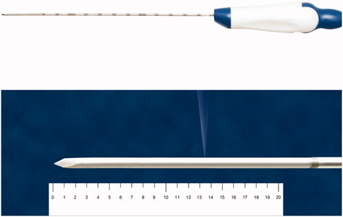
Additionally, 17-gauge ICWT and ICT electrodes (Jet-tip and Big-tip, RF Medical Co., Seoul, Korea) with a 2-cm exposed tip were used in this study. The exposed tip of the ICWT electrode contains a small side hole through which the saline is perfused. A peristaltic pump (RFP-300) was used to infuse a normal saline solution at 5–10 °C into the lumen of the electrodes to maintain the tip temperature of 10–25 °C. Approximately 99% of the chilled 0.9% isotonic saline was used for cooling, and 1% was used for infusion which was perfused at a rate of 1 cc/min ().
Figure 1. Photograph of an internally cooled wet electrode with a side hole in the active tip for tissue perfusion. The average distance from the electrode tip to the side hole is 13.5 mm ± 0.5 mm. RF medical Co. (Seoul, Republic of Korea) holds copyright of this figure, which was used with permission.
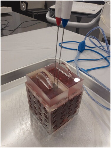
RFA was performed in fresh explanted bovine livers, which were maintained at room temperature. Explanted bovine livers were sliced into blocks to fit in a cube of 8 × 8 × 8 cm3. After placing the liver block into the cube, an acrylic plate was placed on top of the cube. The acrylic plate has multiple holes at 5-mm intervals at the midline of the cube, and through the holes, the electrodes are inserted. The plate is used to ensure that the electrodes are placed accurately at the midline of the liver block, and the distance between the electrodes is constant (). Two electrodes were used for each ablation and were inserted at a depth of approximately 4–5 cm. Areas of the bovine liver with traversing large vessels were assessed using a long screwdriver and were avoided for ablation as much as possible since it may affect the shape of ablation zone.
Figure 2. Radiofrequency ablation settings. Explanted bovine livers were sliced into blocks in order to fit in a cube of 8 × 8 × 8 cm3. After placing the liver block into the cube, an acrylic plate was placed on top of the cube. The acrylic plate has multiple holes at 5-mm intervals at the midline of the cube, and through the holes the electrodes are inserted. The electrodes were inserted at a 1-cm inter-electrode distance.
Pilot studies and estimation of sample size
Before the main experiment, two pilot studies were performed to (1) determine the best protocol in creating a spherical ablation zone using dual ICWT and (2) estimate the sample size required for comparing the sphericity of ablation zones created using ICWT and ICT, respectively. In our study, monopolar ablation was performed first, and bipolar mode was followed. By applying monopolar mode first, we intended to ablate the periphery first to adhere to the concept of centripetal ablation. For the first pilot study, 6 protocols using various combinations of inter-electrode distance (1.5 and 1.0 cm) and ablation time of each energy mode (monopolar 120 W 0, 1, 2 min + bipolar 60 W 1 min + bipolar 80 W 3, 4, 5 min) were tested to determine the best protocol in creating a spherical ablation zone. The planned total ablation time was fixed at 6 min so that it would be comparable to that of microwave ablation. The power of each energy mode followed the manufacturer’s instruction. Four ablations were performed for each pilot study protocol.
Subsequently, a second pilot study was conducted using the protocol retrieved from the first pilot study, and 10 ablation zones were created for each electrode type to compare their sphericity. Ablation zones with aspect ratio (AR, ratio between the principal axis and its maximum perpendicular axis) < 1.2 were considered as acceptable sphericity [Citation11,Citation12]. Based on the results, the sample size needed for the main experiment to obtain 90% power and 0.05 significance was calculated using the Fisher’s exact test.
Main experiment
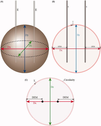
Twenty ablation zones for each electrode type were created for the main experiment using the protocols from the first pilot study. After ablation, the bovine liver blocks were cut first along the electrode tracts. Afterward, a second cut was made in a transverse plane perpendicular to the first cut surface and to the two electrode tracts (). From the first cut surface, the longest diameter perpendicular to the electrode tract that would traverse the two electrode tracts (diameter along the x-axis, Dx) and the longest vertical diameter parallel to the electrode tract at the middle (diameter along the y-axis, Dy) were measured. From the second cut surface, the diameter perpendicular to the first cut line (or perpendicular to Dx) at the midpoint, defined as Dz (diameter along the z-axis), was measured. To prevent any bias in the ablation size measurements, the cut surfaces were photographed alongside a ruler, and the measurements were performed afterward on image files using Image J software (https://imagej.nih.gov). A study coordinator mixed the photographs and presented them to two observers in random order to avoid bias. Only the study coordinator was aware of the type of electrodes used for the ablation of each photograph, whereas the two observers were blinded to this information. They independently measured the three diameters, distances between each electrode and the closest outer margin of the ablation zone along the x-axis (DEM), circularity of the ablation zone on the second cut surface (zx plane), and thickness of peripheral red zones () [Citation13]. They also recorded whether an unexpected vessel was present near the ablation zone margin that could affect its shape.
Figure 3. Schematic figures of ablation zones showing the measured diameters. (A) Three-dimensional figure of the spherical ablation zone. Two electrodes (E) are inserted with a 1-cm inter-electrode distance, and radiofrequency ablation is performed to create a spherical ablation zone. After ablation, the bovine liver blocks were cut first along the electrode tract and second in a transverse plane perpendicular to the first cut surface. From the first cut surface, the longest diameter perpendicular to the electrode tracts that would traverse the two electrode tracts is Dx (red), and the longest vertical diameter parallel to the electrode tract at the middle is Dy (blue). From the second cut surface, the diameter perpendicular to Dx at the midpoint is Dz. Dx: distance along x axis; Dy: distance along y axis; Dz: distance along z axis; E: electrodes. (B) Schematic figure of the first cut surface of the ablation zone showing xy plane. Two electrodes (E) are inserted in parallel. Dx is the longest diameter that traverses the two electrode tracts perpendicularly. Dy is the longest vertical diameter parallel to the electrode tracts, at the midline between the two electrodes. Distance between the electrode tract and the closest outer margin of the ablation zone along the x axis is DEM. The thickness of the peripheral red zone is T. (C) Schematic figure of the second cut surface of the ablation zone showing zx plane. RF electrode tracts are shown as black circles. The ablation zone consists of central white (pale pink) and peripheral red zones (dark pink), and the area of the ablation zone is the sum of the two zones. Circularity on zx plane was measured by drawing a region of interest along the outer margin of the ablation zone. Dx: distance along x axis; Dz: distance along z axis; DEM: Distance between the electrode tract and the closest outer margin of the ablation zone along the x axis; T: thickness of peripheral red zone.
The circularity of the ablation zone was measured on the zx plane only because Dz was the key diameter in determining the shape of the ablation zone as it showed the most difference between ICWT and ICT and was the shortest diameter. Circularity was automatically calculated by drawing a region of interest along the outer margin of the ablation zone on the Image J software. Circularity was defined as C = 4πA/P2, where A was the area of the measured zone, and P was the perimeter of the area.
The average values of the two observers were used for analysis. Using the average values, AR, quantitative sphericity and volume of each ablation zone were calculated. Dz, which was the principal axis, and the longer Dx and Dy were used for AR measurement. Quantitative sphericity measurement was calculated using the following equation: S = (c2/ab)⅓, (a [major axis length], b [medium axis length] and c [minor axis length]) [Citation14,Citation15], with Dz being the minor length in all ablation zones. The volume of ablation zones was calculated using the following equation: V = π (Dx × Dy × Dz)/6. Since the amount of energy consumed during ablation may affect the size of the ablation zone, the correlation between the consumed energy in each sample and the resultant ablation volume were evaluated. The Dx, Dy, and Dz normalized by energy consumption (nDx, nDy, and nDz, respectively) were also calculated. Afterward, a subgroup analysis was performed for ablation zones without unexpected vessels at the ablation zone margin to reduce the effect of vessels on the ablation zone shape.
Statistical analyses
The continuous and categorical variables are presented as median with range and as number with percentage, respectively. The Mann–Whitney U test was used to compare the continuous variables, whereas the Fisher’s exact test was used for the comparison of sphericity defined by AR. The correlation coefficient was used to correlate the ablation zone volume and the amount of consumed energy during ablation. A p value <.05 was considered statistically significant. Statistical analysis was performed using R version 3.5.0 (The R Foundation for Statistical Computing).
Results
Pilot studies
Ablation without monopolar mode resulted in too short diameter along the axis containing the two electrode paths, whereas this diameter did not seem to differ between 2 and 1 min of monopolar ablation. Moreover, when the inter-electrode distance was 1.5 cm, the shape of ablation zone tended to be ovoid compared with 1 cm of inter-electrode distance. Consequently, the results from the pilot study showed that a combination of 2.0-cm exposed tip, 1.0-cm inter-electrode distance and 1-min monopolar (120 W) + 5-min bipolar (1-min 60 W + 4-min 80 W) mode was the best combination to create a 3-cm spherical ablation zone ().
Table 1. Results of the first pilot study for identifying the best protocol in creating a 3 cm sized spherical ablation zone using internally cooled wet tip electrode.
The result from the second pilot study showed that the proportion difference of ablation zones with AR < 1.2 was 0.6 between ICWT (90%, 9/10) and ICT (30%, 3/10). The calculated sample size required for the main experiment was 16 ablation zones for each electrode type.
Main experiment
summarizes the results of the main experiment. Dx and Dz were significantly longer with ICWT than those with ICT (p = .018 and p < .001, respectively). Dy was not significantly different (p = .220) (). Acceptable sphericities with AR < 1.2 were 85% (17/20) with ICWT and 30% (6/20) with ICT (p = .001), respectively, with quantitative measurement also showing that ICWT was more spherical compared to ICT (p = .001). The ablation volume was also significantly higher with ICWT than with ICT () (p = .003).
Figure 4. Box and whisker plots showing the differences of Dx, Dy, and Dz between dual internally cooled wet tip (ICWT) and dual conventional internally cooled tip (ICT) electrodes, both (A) original values and (B) their values after normalized by energy consumption. Dx and Dz were significantly longer with ICWT than those with ICT (p = .018 and p < .001, respectively). Dy was not significantly different (p = .220). The results were similar even after the diameters were normalized by energy consumption (Dx, p = .021; Dy, p = .257; and Dz, p < .001).
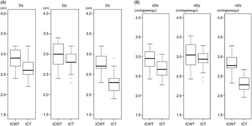
Figure 5. Cut surfaces of ablated bovine liver blocks in which dual internally cooled wet tip (ICWT) and dual conventional internally cooled tip (ICT) electrodes were used. (A) xy plane and (B) zx plane of the ablation zone using dual ICWT electrodes, and (C) xy plane and (D) zx plane of the ablation zone using dual ICT electrodes, respectively. The ablation zones from ICWT were more circular at zx plane due to Dz similar to Dx, and the overall shape was also more spherical than those from ICT. Therefore, the overall ablative volume using ICWT was larger than using ICT.
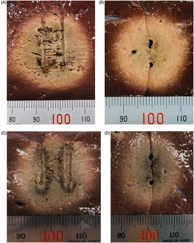
Table 2. Comparison of ablation zone measurements between internally cooled wet tip (ICWT) and conventional internally cooled tip (ICT) electrode. Results are based on Entire Experimental Dataset.
DEM was also significantly longer with ICWT than that with ICT (p = .011), although the absolute difference was small (median, 1.0 cm vs. 0.9 cm, respectively). The ablation zone on the zx plane was more circular with ICWT than that with ICT (p = .028). The thickness of peripheral red zones was not significantly different between ICWT and ICT (p = .080). The amount of energy applied was significantly higher with ICWT than that with ICT (p = .003).
The correlation coefficients between the energy consumed and the volume of ablation zone were −0.07 for ICWT and 0.56 for ICT (). The normalized diameters showed similar results with the original diameters; nDx and nDz were significantly longer with ICWT than those with ICT (p = .021 and p < .001, respectively), and nDy was not significantly different (p = .257) ().
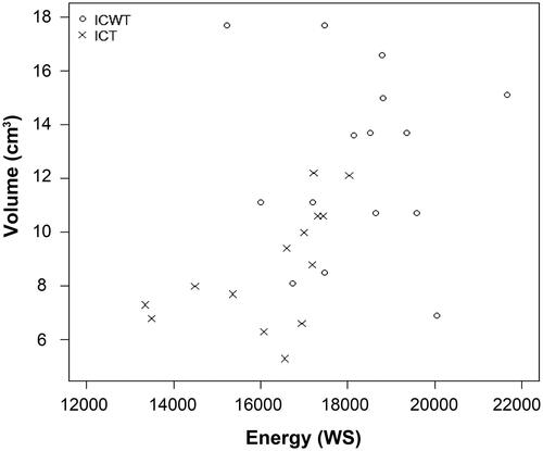
Figure 6. Correlation between consumed energy during ablation and ablation zone volume using dual internally cooled wet tip (ICWT) and dual conventional internally cooled tip (ICT) electrodes. The correlation coefficient between the energy consumed and the volume of ablation zone induced by ICWT and ICT group were −0.07 for ICWT and 0.56 for ICT. The plots within the graph for ICWT are scattered. Even though ICT had a coefficient value of 0.56, the distribution does not seem to be linear.
After excluding distorted shape ablation zones due to unexpected vessels within the ablation zones, the results showed that the sphericities of ablation zones based on AR < 1.2 were 100% (15/15) with ICWT and 29.4% (5/17) with ICT (p < .001), respectively. Quantitative measurement also confirmed this result (p < .001). The ablation volume was also significantly bigger with ICWT than with ICT (p = .004) ().
Table 3. Comparison of ablation zone measurements between internally cooled wet tip (ICWT) and conventional internally cooled tip (ICT) electrode. Results are based on selected dataset that includes ablation zones without unexpected vessels at the ablation zone margin.
Discussion
RFA techniques are still evolving, with new-generation ablation techniques and devices that are more effective at creating larger ablation zones than before [Citation16,Citation17]. In the present study, we aimed to determine an ablation protocol that can create a spherical ablation zone using two electrodes during a short procedure time (6 min) comparable to microwave ablation with a single antenna.
Our study shows that RFA using dual ICWT was able to create a more spherical and larger ablative volume than using dual ICT. Spherical ablative zones, defined by AR < 1.2, were found in 85% (17/20) with ICWT and 30% (6/20) with ICT (p = .001). Specifically, when considering ablation zones without unexpected vessels at the ablation zone margin only, surprisingly, the sphericities were 100% (15/15) with ICWT and 29.4% (5/17) with ICT (p < .001). Quantitative sphericity measurement was also significantly higher with ICWT than that with ICT, which was demonstrated in both the entire and subgroup datasets (p = .001, and p < .001, respectively). Ablation zones from ICWT were also more circular than those from ICT on the zx plane, whereas those from ICT were rather ovoid (p = .028). As the measurements from the main study are similar to those of the first pilot study, our 6 min ablation protocol seem reproducible and work well for creating a relatively spherical ablation zone with the ICWT electrode.
ICWT using our protocol, resulting in more spherical and circular ablation zones, would primarily be due to the difference in Dz (p < .001), which had the major difference between the two electrodes. The high ablative performance of ICWT electrodes would be due to the synergy between the properties of ICWT electrode, which disperse saline into the active ablation zone to increase electrical conductivity, decrease tissue impedance, and prevent charring of active tip to enable more energy to be radiated from the electrode to create a larger ablation volume than conventional ICT electrode [Citation10] and bipolar mode, which can create faster and more homogeneous complete necrosis of the ablation zone [Citation3,Citation18].
In the present study, the bipolar mode was performed for 5 min, which was the main energy source for ablating the liver between the two electrodes. Bipolar mode has superior theoretical properties because electric current oscillates between the interstitial electrodes placed within the liver. Therefore, currents are mainly restricted between the electrodes. Additionally, although it is generally reported that the shape of ablation zone using one ICWT electrode is more irregular than ICT electrodes, our study shows that using two ICWT electrodes with bipolar mode was able to create a rather uniform spherical ablation zone probably due to its more powerful ablative performance, thus lowering the concern of ablation zone shape irregularity.
The monopolar mode achieved sufficient ablative margin along the x-axis beyond the two electrodes considering that previous studies have reported that DEM from bipolar mode was shorter than that from monopolar mode [Citation19,Citation20]. Monopolar mode was applied for 1 min only to avoid excessively large ablation zone, specifically along the x-axis. DEMs were approximately 1 cm and 0.9 cm with ICWT and ICT, respectively, which was significantly different (p = .011), although the absolute difference was small. Dx would also have been determined by monopolar ablation and was significantly longer with ICWT than with ICT (p = .018).
Our results demonstrate an advantage of ICWT over ICT, as only two electrodes were required to create a relatively spherical ablation zone, which is usually achieved using three or more ICT electrodes. RFA with two ICWT electrodes, similar to our protocol, also has theoretical advantages over conventional tumor-puncturing RFA using a single electrode. It will allow centripetal ablation since two electrodes can be inserted at the tumor periphery where tumor cell proliferation is most active, enabling more efficient eradication of tumor cells. Additionally, it allows early thrombotic occlusion of tumor feeding vessels and more efficient elimination of microscopic satellite nodules due to sufficient achievement of DEM, eventually leading to a more efficient local tumor control. If thrombotic occlusion of feeding vessels occurs in the early period of the RFA process, potential tumor spread through the peritumoral vessels by increased intratumoral pressure would be avoided. This was why the monopolar RFA was applied first, then the bipolar mode in our study. Our ablation protocol can be modified according to tumor size and geometry. For example, inter-electrode distances can be increased, and overall ablation time can be extended to increase the size of the ablation zones for larger tumors. Our protocol, which utilizes bipolar mode as the primary energy source for ablation, would also be safe since ablation mainly occurs between the electrodes. Thus, a significantly large radial ablative margin can be avoided [Citation19].
Meanwhile, Dy was considered to be determined by active tip length and was not significantly different between the two electrodes (p = .220). The ablation volume was also significantly larger with ICWT than that with ICT (p = .003) due to the differences in ablation zone diameters. The thickness of the peripheral red zones, comprising a mixture of damaged and dead cells rather than totally dead cells [Citation13], was small in both electrodes, indicating that the rather short 6-min ablation time was sufficient in creating a 3-cm ablation zone. The amount of applied energy was also bigger with ICWT than that with ICT (p = .003), which would correspond with the larger ablation volume since the amount of applied energy is reported to correspond to the volume of the ablation zone [Citation21] and thus would be more time-energy efficient [Citation22].
The correlation between the energy consumed and the volume of the ablation zone was not high for both types of electrodes, especially with ICWT. This is in line with previous studies demonstrating that the ablation zone shape and size using ICWT are irregular and unpredictable [Citation23–25]. It has been suggested that the infused saline may flow irregularly further into the tissue, leak along the electrode track, and maybe absorbed by the vascular and lymphatic system. As the effect of infused saline per volume is not consistent, the resultant ablation volume would also be irregular. Even though ICT had a coefficient value of 0.56, the plots within the graph showing the correlation between the consumed energy and the ablation volume do not seem to be linear. In general, the extent of coagulation necrosis induced in a given lesion is equal to the energy deposited, modified by local tissue interactions, minus the heat lost before inducing thermal damage [Citation26]. Loss of energy due to the interfering factors may be the reason for the low correlation between ablation volume and energy consumption.
This study has several limitations. First, this was an ex vivo study, and its results were not verified in in vivo. However, our results provide potential advantages of ICWT by using a combination of monopolar and bipolar modes in creating spherical ablation zones that may allow centripetal ablation if the two electrodes are positioned at the periphery of the tumor. Further tests, including in vivo experiments, would be required to verify our results. Second, the ablations were performed in hepatic parenchyma, not with hepatic tumors; therefore, specific results may differ if performed with hepatic tumors. However, considering that this protocol using bipolar mode would be applied for centripetal ablation where electric current is mostly focused at the center where the tumor would be, this may not significantly affect the results of our study. Third, a histologic analysis was not performed to evaluate cell necrosis. However, previous studies have demonstrated that central white zone corresponds with total necrosis, whereas peripheral red zone is a mixture of dying and dead cells [Citation13]. Considering that the peripheral red zone was thin in our study, this would not significantly affect our results.
In conclusion, dual ICWT electrodes were better able to create more spherical and larger ablation zones than dual ICT electrodes.
Acknowledgment
This study received technical support from RF Medical Co. (Seoul, Republic of Korea). The authors had full control of the data and information submitted for publication at all times.
Disclosure statement
No potential conflict of interest was reported by the author(s).
Additional information
Funding
References
- European Association for the Study of the Liver. Corrigendum to “EASL Clinical Practice Guidelines: management of hepatocellular carcinoma” [J Hepatol 69 (2018) 182-236]. J Hepatol. 2019;70(4):817.
- Marrero JA, Kulik LM, Sirlin CB, et al. Diagnosis, staging, and management of hepatocellular carcinoma: 2018 practice guidance by the American Association for the Study of Liver Diseases. Hepatology. 2018;68(2):723–750.
- Ahmed M, Brace CL, Lee FT, Jr, et al. Principles of and advances in percutaneous ablation. Radiology. 2011;258(2):351–369.
- Ahmed M, Solbiati L, Brace CL, et al.; Standard of Practice Committee of the Cardiovascular and Interventional Radiological Society of Europe. Image-guided tumor ablation: standardization of terminology and reporting criteria – a 10-year update. Radiology. 2014;273(1):241–260.
- Lee JM, Han JK, Kim HC, et al. Switching monopolar radiofrequency ablation technique using multiple, internally cooled electrodes and a multichannel generator: ex vivo and in vivo pilot study. Invest Radiol. 2007;42(3):163–171.
- Dodd GD, 3rd, Frank MS, Aribandi M, et al. Radiofrequency thermal ablation: computer analysis of the size of the thermal injury created by overlapping ablations. AJR Am J Roentgenol. 2001;177(4):777–782.
- Park MJ, Kim YS, Rhim H, et al. A comparison of US-guided percutaneous radiofrequency ablation of medium-sized hepatocellular carcinoma with a cluster electrode or a single electrode with a multiple overlapping ablation technique. J Vasc Interv Radiol. 2011;22(6):771–779.
- Lee J, Lee JM, Yoon JH, et al. Percutaneous radiofrequency ablation with multiple electrodes for medium-sized hepatocellular carcinomas. Korean J Radiol. 2012;13(1):34–43.
- Federle MP, Lau JN. Imaging in abdominal surgery E-book. Philadelphia: Elsevier Health Sciences; 2019.
- Cha J, Choi D, Lee MW, et al. Radiofrequency ablation zones in ex vivo bovine and in vivo porcine livers: comparison of the use of internally cooled electrodes and internally cooled wet electrodes. Cardiovasc Intervent Radiol. 2009;32(6):1235–1240.
- Dukic-Ott A, De Beer T, Remon JP, et al. In-vitro and in-vivo evaluation of enteric-coated starch-based pellets prepared via extrusion/spheronisation. Eur J Pharm Biopharm. 2008;70(1):302–312.
- Dukic A, Mens R, Adriaensens P, et al. Development of starch-based pellets via extrusion/spheronisation. Eur J Pharm Biopharm. 2007;66(1):83–94.
- Song KD, Lee MW, Rhim H, et al. Chronological changes of radiofrequency ablation zone in rabbit liver: an in vivo correlation between gross pathology and histopathology. Br J Radiol. 2017;90(1071):20160361
- Hayakawa Y, Oguchi T. Evaluation of gravel sphericity and roundness based on surface-area measurement with a laser scanner. Comput Geosci-UK. 2005;31(6):735–741.
- Cruz Matías IA, Vallespí A. Orientation, sphericity and roundness evaluation of particles using alternative 3D representations. 2014 [cited 2020 June 1]. https://www.semanticscholar.org/paper/Orientation%2C-sphericity-and-roundness-evaluation-of-Mat%C3%ADas-Vallesp%C3%AD/ab536f0f6b103505b1310d325e65873364270125.
- Choi TW, Lee JM, Lee DH, et al. Percutaneous dual-switching monopolar radiofrequency ablation using a separable clustered electrode: a preliminary study. Korean J Radiol. 2017;18(5):799–808.
- Hocquelet A, Aube C, Rode A, et al. Comparison of no-touch multi-bipolar vs. monopolar radiofrequency ablation for small HCC. J Hepatol. 2017;66(1):67–74.
- Seror O, N'Kontchou G, Van Nhieu JT, et al. Histopathologic comparison of monopolar versus no-touch multipolar radiofrequency ablation to treat hepatocellular carcinoma within Milan criteria. J Vasc Interv Radiol. 2014;25(4):599–607.
- Chang W, Lee JM, Lee SM, et al. No-touch radiofrequency ablation: a comparison of switching bipolar and switching monopolar ablation in ex vivo bovine liver. Korean J Radiol. 2017;18(2):279–288.
- Chang W, Lee JM, Yoon JH, et al. No-touch radiofrequency ablation using multiple electrodes: an in vivo comparison study of switching monopolar versus switching bipolar modes in porcine livers. PLoS One. 2017;12(4):e0176350.
- Clasen S, Schmidt D, Dietz K, et al. Bipolar radiofrequency ablation using internally cooled electrodes in ex vivo bovine liver: prediction of coagulation volume from applied energy. Invest Radiol. 2007;42(1):29–36.
- Yoon JH, Lee JM, Woo S, et al. Switching bipolar hepatic radiofrequency ablation using internally cooled wet electrodes: comparison with consecutive monopolar and switching monopolar modes. BJR. 2015;88(1050):20140468.
- Schmidt D, Trübenbach J, Brieger J, et al. Automated saline-enhanced radiofrequency thermal ablation: initial results in ex vivo bovine livers. AJR Am J Roentgenol. 2003;180(1):163–165.
- Lee JM, Han JK, Kim SH, et al. Optimization of wet radiofrequency ablation using a perfused-cooled electrode: a comparative study in ex vivo bovine livers. Korean J Radiol. 2004;5(4):250–257.
- Denys AL, De Baere T, Kuoch V, et al. Radio-frequency tissue ablation of the liver: in vivo and ex vivo experiments with four different systems. Eur Radiol. 2003;13(10):2346–2352.
- Goldberg SN, Gazelle GS, Mueller PR. Thermal ablation therapy for focal malignancy: a unified approach to underlying principles, techniques, and diagnostic imaging guidance. AJR Am J Roentgenol. 2000;174(2):323–331.