
 ?Mathematical formulae have been encoded as MathML and are displayed in this HTML version using MathJax in order to improve their display. Uncheck the box to turn MathJax off. This feature requires Javascript. Click on a formula to zoom.
Abstract
Background
Proactive cooling with a novel cooling device has been shown to reduce endoscopically identified thermal injury during radiofrequency (RF) ablation for the treatment of atrial fibrillation using medium power settings. We aimed to evaluate the effects of proactive cooling during high-power short-duration (HPSD) ablation.
Methods
A computer model accounting for the left atrium (1.5 mm thickness) and esophagus including the active cooling device was created. We used the Arrhenius equation to estimate the esophageal thermal damage during 50 W/ 10 s and 90 W/ 4 s RF ablations.
Results
With proactive esophageal cooling in place, temperatures in the esophageal tissue were significantly reduced from control conditions without cooling, and the resulting percentage of damage to the esophageal wall was reduced around 50%, restricting damage to the epi-esophageal region and consequently sparing the remainder of the esophageal tissue, including the mucosal surface. Lesions in the atrial wall remained transmural despite cooling, and maximum width barely changed (<0.8 mm).
Conclusions
Proactive esophageal cooling significantly reduces temperatures and the resulting fraction of damage in the esophagus during HPSD ablation. These findings offer a mechanistic rationale explaining the high degree of safety encountered to date using proactive esophageal cooling, and further underscore the fact that temperature monitoring is inadequate to avoid thermal damage to the esophagus.
1. Introduction
Atrioesophageal fistula (AEF) is a serious complication of ablation procedures during the performance of pulmonary vein isolation (PVI) for the treatment of atrial fibrillation, with a mortality rate as high as 80% [Citation1,Citation2]. Although the rate of AEF after PVI is often assumed to be around 0.2%, AEF is most certainly underreported. This is due to the fact that the presentation of AEF is delayed, the clinical picture mimics the much more common presentation to the emergency department of sepsis, and the diagnosis is difficult even if the condition is suspected [Citation3,Citation4]. Recent randomized controlled trials also suggest the rate may be higher than generally appreciated [Citation5–7]. Various approaches have been taken to reduce the occurrence of AEF, including reducing power to the posterior wall, monitoring luminal esophageal temperature (LET), deviating the esophagus, and actively cooling the esophagus. Many of these approaches have been shown to be either ineffective or to potentially increase esophageal injury rates [Citation8–13].
Active cooling can be performed either reactively, with manual cold-water instilled via gastric tube in response to measured LET rise, or proactively, with a dedicated cooling device providing cooling throughout the duration of the ablation procedure. Reactive cooling (where cooling is provided after a thermal insult has been detected by a LET monitoring probe) has been shown to have some benefit in a meta-analysis in reducing severe esophageal injury by 61% [Citation14]. On the other hand, proactive cooling (where the temperature of the esophagus is preemptively reduced before ablation begins, using a dedicated cooling device) has shown greater benefits, with reductions in severe esophageal lesion formation of 67%–83% [Citation15–17]. The rapidly growing use of proactive esophageal cooling during PVI has resulted in the publication or presentation of data on thousands of patients, and well over 10,000 ablations have now been completed with no AEF formation yet reported, and only a single pericardio-esophageal fistula known to have occurred [Citation18–20].
With better-than-expected clinical safety being reported using proactive esophageal cooling, additional mechanisms of protection beyond mere dissipation of heat appear to be involved. A thermal insult is almost certainly a prerequisite for AEF formation [Citation21,Citation22], with thermal latency contributing to lesion growth even after the cessation of radiofrequency (RF) energy application [Citation23,Citation24]. Recent developments in the field of burn injury healing suggest that alteration of cellular behavior with cooling may also be a factor in preventing injury progression (by decreasing release of lactate and histamine, stabilizing thromboxane and prostaglandin levels, altering membrane permeability, inhibiting kallikrein activity and altering gene expression) [Citation21,Citation25–28]. With attainment of lethal isotherm temperature in esophageal tissue likely the inciting event from which AEF development begins, we aimed to evaluate using computer modeling the effects of proactive esophageal cooling on thermal damage in the esophagus during high-power short-duration (HPSD) ablations.
2. Methods
We used mathematical modeling to study the physical phenomena involved during RF catheter ablation of the left atrium with and without proactive esophageal cooling. A 3D model was built and solved using the finite element method with the software COMSOL Multiphysics (COMSOL, Burlington, MA, USA). The model makes use of Pennes’ Bioheat equation and includes accommodations for the phase change of tissues during the RF ablation.
2.1. Model geometry
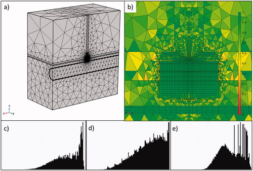
shows the active cooling device on the left panel, and shows the model geometry, including all the relevant tissues and their proximity to the ablation target: atrial wall, epicardial fat, esophagus/connective tissue and blood (cardiac chamber). A cylindrical structure was assumed to be embedded into the connective tissue in order to model the esophageal lumen occupied by an active cooling device (ensoETM, Attune Medical, Chicago, IL, USA). This device was modeled as a hollow silicone tube (1.2 cm diameter, 0.65 mm wall thickness) full of cold water which is circulated by a pump. Control conditions, in which no active cooling device was present, were modeled by a collapsed esophagus. In this case, the subdomain corresponding to the cooling device was replaced with the properties of ‘esophagus and other tissues’. The model considered an irrigated-tip electrode (7 Fr, 4 mm) placed perpendicularly on the atrial wall surface and inserted to a depth of 0.5 mm. Only half of the physical domain was considered as both the geometry and the physics are symmetric. Tissue thickness was set to average posterior-wall dimensions: 1.5 mm, 0.75 mm and 2 mm for the atrial wall, fat layer and the esophagus [Citation29–31].
Figure 1. (a) Physical situation to be modeled with an active cooling device located in the esophageal lumen. (b) Model geometry including RF catheter, tissues near the ablation site and an active cooling device located in the esophageal lumen. The evaluation line (black line) for post-processing is shown across the ablated tissues, from tip of RF catheter to edge of active cooling device (with tissues including myocardium, fat and esophagus).

2.2. Governing equations
The Maxwell equations and the Bioheat equation were used to solve electric and thermal problems involved during RF ablation. The degree of thermal damage was calculated using the Arrhenius model [Citation21,Citation24,Citation31,Citation32]. In electromagnetic terms, the skin depth at 500 kHz for biological tissues is on the order of 1 m, suggesting that there are hardly any opposing eddy currents induced by the changing magnetic field resulting from the RF current. In other words, electric and magnetic fields can be considered decoupled and, consequently, the electric field E (V/m) can be computed by using the frequency-domain electric Maxwell equations (EquationEquations (1–3)) [Citation33]
(1)
(1)
(2)
(2)
(3)
(3)
where J is the current density (A/m2), D is the electric displacement (C/m2), Φ is the electric potential (V),
is the frequency (500 kHz for RF catheter ablation) and σ is the electric conductivity (S/m). The electrical problem is computed in all the subdomains shown in blood, myocardium, catheter tip and body, esophagus, surrounding tissues and cooling device (wall and circulating water).
The thermal problem was solved using the Bioheat equation [Citation34]:
(4)
(4)
where T is the temperature (°C), ρ is the density (kg/m3),
is the specific heat capacity at constant pressure (J/kg·K) and k is the thermal conductivity (W/m2·K). The thermal problem is computed in all the subdomains except in the blood. Additionally, a term corresponding to thermal advection is considered specifically for the subdomain corresponding to the cold circulating water (i.e. inside the silicone tube), leaving EquationEquation (4)
(4)
(4) as follows:
(5)
(5)
where u is the velocity field for this subdomain (m/s), which is obtained from the inner area of the tube and the rate used in clinics (60 L/h). The degree of thermal damage α is described according to the Arrhenius formulation (EquationEquation (6)
(6)
(6) ) where the fraction of damage (FOD)
ranges from 0 and 1, and can be calculated with EquationEquation (7)
(7)
(7) .
(6)
(6)
(7)
(7)
where A is the frequency factor (s−1), Ea is the activation energy (J/mol), n is the reaction order and R is the gas constant (8.3145 J/mol·K). Values of 0.63 (63%) and 0.99 (99%) are commonly used to represent permanent tissue damage [Citation24,Citation35]. Lesion sizes were estimated at two times: just after the RF pulse, and up to 90 s after RF pulse onset to account for lesion expansion due to thermal latency.
The heat sources Qbio and QRF (W/m3) correspond to biological and electromagnetic phenomena, respectively. The term Qbio is composed of metabolic (Qm) and perfusion (Qp):
(8)
(8)
The metabolic heat is negligible compared to the energy dissipation and was hence ignored [Citation36]. The perfusion heat was given by:
(9)
(9)
where the following blood properties are involved: ρbl is the density (kg/m3), Cp,bl is the heat capacity in (J/kg·K), ωbl is the perfusion rate (s−1), Tbl is the blood temperature (37 °C) and β is a non-dimensional parameter to simulate that blood perfusion ceases once tissue is completely destroyed by thermal necrosis (β = 1 while fraction of thermal damage remains less than 99% and β = 0 for 100% damage). The perfusion rate for each tissue is taken from the ITIS database [Citation37]. The RF-induced heat source is due to Joule effect and is given by:
(10)
(10)
The irrigated electrode was modeled with a heat source with a mathematical structure similar to blood perfusion and given by EquationEquation (9)(9)
(9)
(11)
(11)
where the following saline water properties are involved: ρH2O is the density (kg/m3), Cp,H2O heat capacity (J/kg·K), ωH2O catheter irrigation rate (s−1) and TH2O water temperature (assumed to be 25 °C). This method mimics the cooling effect by saline circulating inside the electrode, and it has been broadly used in computer models of energy-based cooled applicators [Citation35].
2.3. Boundary and initial conditions
We modeled constant power RF ablation by applying a power value at the interface between the catheter tip and body. Some electrical losses happen in the body beyond the zone around the ablation electrode, and this loss has been shown to be approximately 20% [Citation38]. As such, only 80% of the value used in clinical practice was used for the simulation. Two HPSD settings were simulated: 50 W for 10 s and 90 W for 4 s. The active cooling device considered cold water at 4 °C (inflow temperature) flowing at a rate of 60 L/h in the x direction (see ). The water velocity u was directly defined in the heat transfer equation (see EquationEquation (5)(5)
(5) ) and the transport of water flow was not therefore studied using momentum equations. The blood subdomain was exclusively considered in the electric problem. The thermal effect of the circulating blood on electrode and myocardium surface was considered with convective heat flux boundary conditions. The convective heat flux
(in W/m2) through the blood–electrode and blood–myocardium interfaces was given by:
(12)
(12)
where h is the heat transfer coefficient (in W/m2·K) and Tbl is the blood temperature (37 °C). The values for h were 610 W/m2·K and 3346 W/m2·K for blood–electrode and blood–myocardium interfaces, respectively, which simulated ablation sites with low local blood flow (0.085 m/s), as in patients with chronic atrial fibrillation and dilated atria [Citation39]. The symmetry boundary condition was used for the symmetry boundaries (see ). The rest of the external boundaries were set with 0 V for the electric problem and as thermal insulation (no flux) for the thermal problem.
2.4. Material properties
shows the thermal and electric properties for each material [Citation31,Citation32]. The parameters for the Arrhenius damage model were: n = 1, A = 4.43·1016 s−1 for fat and 7.39·1039 s−1 for the rest of the tissues, and Ea = 1.30·105 J/mol for fat and 2.59·105 J/mol for the rest of the tissues [Citation31,Citation32,Citation40]. The variation with temperature of the electric conductivity, density, thermal conductivity and the heat capacity were considered for the all the tissues. These variations were represented using the following equations with the temperature in °C:
(13)
(13)
(14)
(14)
(15)
(15)
(16)
(16)
Table 1. Material properties of the computer model.
The variations of density and thermal conductivity were taken from COMSOL predefined functions for human myocardium while the reference values were taken from the ITIS database [Citation37]. The electric conductivity and the heat capacity were specified to increase linearly (EquationEquations (13)(11)
(11) and Equation(14)
(12)
(12) ) and then change near 100 C to account for the water loss associated with the evaporation phenomenon [Citation39]. EquationEquation (14)
(14)
(14) describes the heat capacity of the tissue during heating below the boiling point of water, but above this value, the formation of bubbles can occur. The effect of this phase change on the temperature distribution in the tissue is therefore included. Between 30 °C and 110 °C, EquationEquation (17)
(17)
(17) describes the vaporization latent heat of water (
kJ/kg). In this equation,
and
(17)
(17)
Since the exact description of the possible phase change of the water contained in the tissue due to its temperature increase during ablation is not part of the scope of this study, our approximation is to define a factor that governs the heat transfer from the sensible to the latent enthalpy, which is nothing more than the relationship between the vaporization latent heat of water, evaluated in a temperature range around the boiling point, and the specific heat of tissue. We considered the boiling point of water at 1.0 atm, i.e. 100 °C.
The factor is selected for the temperature range expected (without considering a detailed model of the phase change of the water contained in the tissue). The factor in this case is 555 in a temperature increment of ΔT = 1 °C or 138.75 for ΔT = 4 °C. Both factors showed similar behavior of the peak temperature against time, so the second factor was utilized to achieve easier convergence and reduce the computational cost. Electrical conductivity (σ) was also expected to be affected by evaporation since water loss induces a decrease in the tissue’s ability to conduct electrical current. Our model included this effect by drastically reducing the σ value (by four orders of magnitude) for temperatures above 100 °C [Citation21].
2.5. Solver and verification
The computational domain was discretized using a hybrid mesh consisting of both tetrahedral and quadrilateral elements ()). The mesh was refined around the electrode, where the changes in the dependent variables and material properties are expected to present the most representative changes. The ‘Mesh Control Faces’ option in COMSOL was used to refine the mesh around the electrode area and to guarantee perfect symmetry of the mesh in the yz plane. The mesh element quality histograms with different criteria (skewness, volume vs. rate and growth rate) for the elements around the electrode are shown in ). A good mesh must have as best element quality as possible, and the more the histogram distribution tends to the right, the better is the mesh quality. The convergence test was done by using a finer mesh with a duplicated number of elements, keeping the proportion of elements in each region and the element quality. The results for fraction of damage, used to calculate the lesion depth and width, were used for convergence criterion. The results between the original and finer mesh remained within 2%.
Figure 2. General view (a) and zoom-in (b) of the meshing around the electrode with 162,322 total elements and 102,250 around the catheter electrode. The color legend represents skewness element quality. Histograms of element quality around the electrode showing the skewness (c), volume versus length (d) and growth rate (e).
In clinical terms, the device pre-cooling time (which is the time the proactive cooling device is performing inside the patient body before RF pulses begin) is around 5–10 min, which is enough to achieve the stationary state. In consequence, in order to consider this pre-cooling time, a first stationary step was added (the results showed that 5 min was enough to reach a steady state in which the temperature varies less than 0.1 °C). Then, a second frequency-transient step takes the stationary results as initial values to run the ablation procedure, the frequency-transient option in COMSOL allows calculating the electric field in the frequency domain and the temperature as a time-dependent variable. The solution time was set as the ablation duration according to the different ablation setups (50 W or 90 W), while the time step was set as 0.02 times the ablation duration. Finally, a third step is added to calculate the temperature and tissue damage 1 min after the ablation catheter is turned off with a step of 1 s.
The segregated solver was set to solve the electric currents with the BiCGStab iterative method, the temperature with the PARDISO direct method and the Arrhenius equation with the MUMPS direct method. For the second and third steps, the high nonlinearities of the model given by the extreme changes in the material properties (electrical conductivity and heat capacity) due to the water evaporation around 100 °C, were controlled by adjusting the nonlinear method to the COMSOL option automatic highly nonlinear (Newton). The solver tolerance and time step were set as ‘physics controlled’ and established automatically by COMSOL. Simulations of both the control condition (no active cooling) and the experimental condition with active cooling were completed.
3. Results
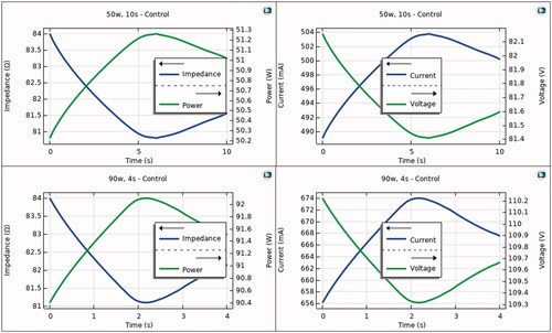
shows the progress of the electrical variables during the RF pulse in the control case, i.e. without proactive esophageal cooling. As expected, the power remains almost constant throughout the RF pulse, despite impedance variations. The impedance shows an initial decrease and a slight increase just after the end of the pulse, which causes variations in the electrical current. The applied voltage is then suitably modulated in order to keep the power constant.
Figure 3. Progress of electrical variables (power, impedance, current and voltage) during RF pulse using 50 W/10s (top) and 90 W/4s (bottom). Note that power is almost constant during the RF pulse, with variations less than 2 W.
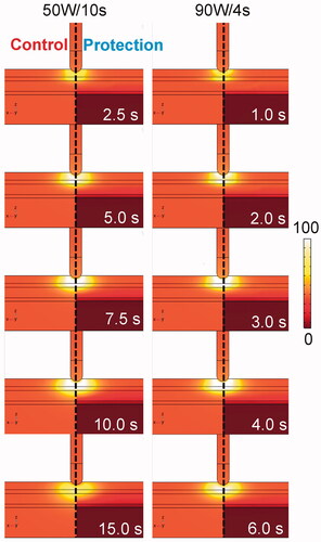
shows the temperature distributions in the tissue undergoing HPSD with (protection) and without (control) proactive esophageal cooling. The impact of esophageal cooling on the increase in temperature in the vicinity of the esophagus is clearly visible. The average temperature increase of the cooling water inside the active cooling device was 0.22 °C in any case (computed at the outflow).
Figure 4. Temperature distributions during HPSD ablation using 50 W/10s and 90 W/4s, with (protection) and without (control) proactive esophageal cooling (scale in °C).
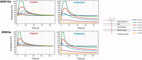
shows the temperature progress at different depths below the electrode. The temperature just at the tip of the RF electrode undergoes a slight increase until it reaches about 45– 50 °C. Possibly 1 mm away is the hottest point, which shows rapid increases in temperature up to 100 °C. As we move away from the electrode, the temperature peak occurs later, even after the RF power has ceased. For the specific simulated distances, the temperature progress at 3 mm is highly affected by the presence or absence of esophageal cooling: while reaching temperatures of 50– 55 °C for the unprotected case, it remained around 40 °C when esophageal cooling is used. When the protection is used, the temperature close to the esophageal lumen (4 mm depth) remains below 20 °C.
Figure 5. Temperature progress computed at different locations below the electrode during and after RF pulse for 50 W/10s and 90 W/4s, with (protection) and without (control) proactive esophageal cooling. Device wall and cooling water correspond to esophageal tissue in the control case in which no esophageal thermal cooling is used.
shows the lesion shapes computed for 50 W/10s and 90 W/4s, with (protection) and without (control) proactive esophageal cooling. The lesion depths (computed with fraction of damage θd = 63% after 90 s) in the case without proactive esophageal cooling (control) were 3.5 mm for 50 W/10s and 3.1 mm for 90 W/4s, decreasing in the case of cooling: 2.9 mm for 50 W/10s and 2.7 mm for 90 W/4s. Note that the fraction of damage incurred by fat is lower than that of myocardial or esophageal tissue, which is a consequence of tissue parameters incorporated into the Arrhenius equation and reflects known resistance of adipocytes to thermal insult.
Figure 6. Lesion shapes (computed with fraction of damage θd = 63% after 90 s with the Arrhenius model) for 50 W/10s and 90 W/4s, with (protection) and without (control) proactive esophageal cooling. Left sided images show the case after the RF pulse, right sided images show the case after 90 s.
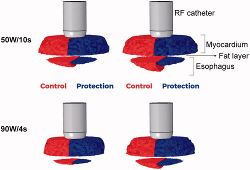
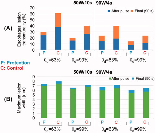
It is noticeable that without active cooling in place, the fraction of damage in the esophagus incorporates an important percentage of the esophageal thickness, whereas with proactive esophageal cooling, the damage is restricted to the epi-esophageal surface, sparing the remainder of the esophageal tissue, including the mucosal surface. This can be also confirmed in , where the percentage of esophageal lesion (using θd = 63%) is around 40 – 60% without protection (control case) and 25– 30% with protection (computed 90 s after RF pulse). Regarding the impact of the active cooling of the esophagus on lesion formation in the atrial wall, as shown in , 100% of myocardial lesions remained transmural, and as shown in , cooling had very little impact on the maximum width (< 0.8 mm).
Figure 7. Esophageal lesion transmurality (a) and maximum lesion width in the myocardial wall (b) computed with two fractions of damage θd (63% and 99%) just after the RF pulse and after 90 s, for 50 W/10s and 90 W/4s, and with (Protection) and without (Control) proactive esophageal cooling.
4. Discussion
4.1. Main findings
Despite the availability of clinical data demonstrating the efficacy and safety of proactive cooling to reduce endoscopically identified thermal injury [Citation15,Citation41,Citation42] during RF catheter ablation, there is no specific information about the lesion size and temperature dynamics during and after the application of high-power short pulses in the case of esophageal proactive cooling. Since it is very complex to obtain this type of information from clinical studies, we built an in silico model and conducted computer simulations to analyze the impact of proactive cooling on temperature distributions, lesion size across the atrial wall and esophageal thermal damage after applying HPSD ablation. Although there are recent experimental data describing the temperature dynamics after these pulses and emphasizing the importance of thermal latency [Citation43,Citation44], none of them considered the presence of a proactive cooling probe. Our motivation was thus to acquire valuable information about these issues, which might provide a physical explanation for the current clinical data.
We report here the first description of temperature across the esophagus during HPSD RF ablation while proactive esophageal cooling is performed. Our model suggests that proactive esophageal cooling protects against thermal insults during HPSD ablation, and does this by precluding the attainment of tissue temperatures reaching or exceeding lethal hyperthermic doses at the esophageal mucosa and across the majority of the esophageal tissue. This in turn significantly reduces the fraction of damage sustained in the esophagus, and offers a mechanistic rationale for the lack of AEF development and the solitary pericardio-esophageal fistula reported, despite thousands of uses to date of proactive esophageal cooling during HPSD ablation.
Results from the model with no active cooling align well with the experimental data recently published. In terms of lesion size, we obtained depths of 3.45 mm for 50 W/10s and 3.05 mm for 90 W/4s and maximum widths of ∼8 mm for 50 W/10s and ∼7 mm for 90 W/4s. These values are in reasonable agreement with those reported by Nakagawa et al. [Citation44] in the beating heart: 4.8 ± 0.9 mm deep and 8.2 ± 1.4 mm wide for 50 W/10s, and 3.6 ± 0.6 mm deep and 7.9 ± 1.2 mm wide for 90 W/4s. The limitations of the experimental models must be also taken into account, since there is an important discrepancy between the reported lesion sizes, possibly due to the different specific conditions of each experimental setup (contact force, temperature limit programmed in the RF generator, etc.). For instance, Leshem et al. [Citation45] reported lesion depths ranging from 1.8 to 3.6 mm for 90 W/4s in the right atrial wall depending on the location (postero-septal and postero-lateral), and widths around 6 mm. Regarding the progress of the temperature inside the tissue, our results reproduce well the thermal latency observed in experiments [Citation43,Citation44]. However, note that a perfect fit is not possible in terms of absolute values of temperature since there is a large gradient in the area near the RF electrode, where the temperature undergoes huge changes in just 1 mm of distance (see ).
Results from the model with proactive cooling showed lower tissue temperature values around the esophagus (see and ). In particular, the peak temperature at 2 mm away from the esophagus lumen (which corresponds approximately with temperature at 3 mm deep) reached ∼55 °C without protection and ∼40 °C with protection. This difference (15 °C) is larger than what we observed in an experiment based on phantom agar using an esophageal balloon cooled at 5 °C (7.5 °C) [Citation46], possibly due to the lower power applied in that case (constant temperature at 55 °C and power always below 50 W) compared to the powers applied here (50 and 90 W). The cooling effect around the esophagus translated into a lower percentage of damaged esophageal wall (see and ). These findings corroborate the data from clinical literature reporting significant safety benefits [Citation18–20,Citation47,Citation48]. A survey of users of proactive esophageal cooling found that 35% utilized 40 W on the posterior wall, and 44% utilized 50 W power settings on the posterior wall [Citation49]. Accordingly, a large percentage of cases performed with proactive esophageal cooling involve high power on the posterior wall. Our findings that proactive esophageal cooling reduces the peak temperatures sustained in esophageal tissue during HPSD ablation offer a theoretical basis to explain the clinical data to date. Our results showed an increment of 0.22 °C in the water temperature inside the device, which is slightly less than that found in clinical practice in elective surgical procedures, where a larger surface area is exposed to heat transfer from the patient, and an increase of water temperature inside the device of up to 0.4 °C has been reported [Citation50]. Nevertheless, both values are very small, which is physically reasonable due to the high volume of coolant flow in clinical use (over 60 L/h). Although cooling shows significant protective effects in the esophageal tissue adjacent to the cooling surface, the effect on atrial myocardium appears unlikely to be of clinical significance. Transmurality of atrial lesions remained at 100% despite active cooling (see ), while differences in lesion width are possibly negligible (< 0.8 mm), especially when linear lesions are created by overlapping consecutive punctual lesions. It is also important to remember that a there is tradeoff between achieving overall smaller lesions (which are needed to minimize esophageal damage, e.g. using proactive cooling) and the need for additional ablation lesions to ensure complete/continuous ablation patterns. This issue could become relevant in case of very short distances between the proactively cooled esophagus and the RF electrode.
It is interesting to discuss the combined effect of electrode irrigation/surface cooling and esophageal protective cooling. The former aims to push the hot spots deeper into the tissue to achieve deeper and better developed lesions, while the latter aims to avoid high temperatures reached in the esophagus. Despite the fact that there are two opposite thermal mechanisms ‘pushing’ the hottest point in the opposite direction, nothing impedes the simultaneous use of irrigated electrodes and esophageal proactive cooling. In fact, in current use in the United States, Europe, Australia and Israel, essentially all operators use irrigated RF catheters with proactive esophageal cooling [Citation15,Citation20,Citation42]. This phenomenon is well illustrated in the progress of temperature at 3 mm depth (see ). While in the control case (without esophageal cooling) the temperature increases due to the ‘hot spot push’ toward the esophagus, in the case of esophageal cooling, the ‘additional push of the hot spot’ toward the endocardium tends to compensate for the first push, managing to more or less stabilize the temperature during the time the RF pulse is applied (around 40 °C).
One of the novel aspects of this study is the specific focus on HPSD ablation. In HPSD ablation, the reliability of LET monitoring is further compromised due to the velocity of temperature rise. A recent study further highlights the inability of LET monitoring to predict thermal injury in HPSD ablation [Citation51]. Our findings in this study suggest that proactive esophageal cooling with a dedicated device is efficient enough to accommodate the rapid changes in temperature that occur with HPSD ablation. Although exact mechanisms behind formation of AEF remain uncertain, growing evidence in the burn literature strongly points to mechanisms triggered by an initial thermal insult, and a subsequent inflammatory cascade that progresses over days to weeks [Citation25–27,Citation52]. Moreover, abundant data demonstrate the ability of cooling to reduce or prevent the progression of burn injuries [Citation27,Citation52,Citation53]. As such, proactive cooling may have a synergistic effect on reducing or preventing the formation of fistulas by (1) reducing peak temperatures that cause the initial thermal insult (thereby limiting the severity of the inciting injury), and (2) lessening the severity of the inflammatory cascade that stimulates progression of burn injury.
4.2. Limitations
Mathematical models provide valuable insight into physical phenomena but may not reflect all clinical findings due to the inherent variability in clinical practice and physiologic parameters. Nonetheless, the elucidation of general principles and ranges of expected findings are helpful in understanding mechanisms involved, and the availability of abundant clinical data and recent experimental data as comparison further strengthens the validity of this model. Debate continues over the exact mechanisms of AEF formation, and additional factors beyond thermal injury may be involved, as discussed above. Although the model described here quantifies the decrease in thermal insult possible with proactive esophageal cooling, it cannot account for downstream effects that may mitigate the production of inflammatory mediators that cause injury progression over days to weeks. Reducing this inflammatory effect may further increase protection against AEF. On the other hand, comparison to existing clinical data may be a suboptimal metric, considering the innumerable variables and dynamic factors involved in the pathophysiology of esophageal thermal injury and AEF. This may be of particular relevance in this condition where varied tissue properties between patients as well as differences in contact forces employed could impact the findings. At this point, considerations such as these, as well as the proximity of the esophagus to surrounding structures and its mobility, can only be accounted for via changes to geometric positioning in the model; however, this model serves as a robust system to further investigate the influence of these factors. Likewise, the impact of the periesophageal vasculature in dissipating heat, as well as potential microvascular effects on ischemic injury and other dynamic phenomena with substantial inter-patient and temporal variation are only partially considered in this model using the Bioheat equation.
In terms of mathematical modeling, the study has also some limitations. First, the blood flow and electrode irrigation were modeled in a simplified way without solving the fluid dynamics. Although this approach is less accurate for predicting surface width, it reasonably predicts lesion depth, and hence it is reasonable to study the thermal impact in deep points (e.g. in the esophagus). Second, mechanical deformation of the endocardial surface was not modeled, i.e. ‘sharp insertion’ of electrode was assumed. Although it is known that this approach overestimates the lesion size compared to the case with ‘elastic insertion’ [Citation54], it is expected that this will affect equally with and without proactive thermal protection, and hence the overall conclusions will not change. And third, while the Arrhenius model was used to estimate the thermal damage, we recognize that other methods could provide different results [Citation55,Citation56]. Likewise, since the mechanism of thermal insult is the same with and without proactive thermal protection, it is expected that the conclusions will be qualitatively the same in case of using a different method to estimate the thermal damage.
5. Conclusions
Proactive esophageal cooling significantly reduces temperatures and the resulting fraction of damage in the esophagus during HPSD ablation. Esophageal damage was restricted to the epi-esophageal region, sparing the remainder of the esophageal tissue, including the mucosal surface. These findings may offer a mechanistic rationale explaining the high degree of safety encountered to date using proactive esophageal cooling. Moreover, these findings further underscore the fact that temperature monitoring is inadequate to avoid thermal damage to the esophagus.
Disclosure statement
M.M.M.: employment with Insilico SE, consulting for Attune Medical; S.R.M.: employment with Acutus Medical, consulting for Attune Medical; T.G.B.: employment with Insilico SE; P.H.A.: employment with Insilico SE; E.K.: equity and employment in Attune Medical. The rest of the authors declare no conflict of interest.
Data availability statement
The data underlying this article will be shared on reasonable request to the corresponding author.
Additional information
Funding
References
- Dagres N, Anastasiou-Nana M. Prevention of atrial-esophageal fistula after catheter ablation of atrial fibrillation. Curr Opin Cardiol. 2011;26(1):1–5.
- Kapur S, Barbhaiya C, Deneke T, et al. Esophageal injury and atrioesophageal fistula caused by ablation for atrial fibrillation. Circulation. 2017;136(13):1247–1255.
- Ha FJ, Han HC, Sanders P, et al. Challenges and limitations in the diagnosis of atrioesophageal fistula. J Cardiovasc Electrophysiol. 2018;29(6):861–871.
- Della Rocca DG, Magnocavallo M, Natale VN, et al. Clinical presentation, diagnosis, and treatment of atrioesophageal fistula resulting from atrial fibrillation ablation. J Cardiovasc Electrophysiol. 2021;32(9):2441–2450.
- Andrade JG, Champagne J, Dubuc M, et al. CIRCA-DOSE study investigators. Cryoballoon or radiofrequency ablation for atrial fibrillation assessed by continuous monitoring: a randomized clinical trial. Circulation. 2019;140(22):1779–1788.
- Kuck KH, Merkely B, Zahn R, et al. Catheter ablation versus best medical therapy in patients with persistent atrial fibrillation and congestive heart failure: the randomized AMICA trial. Circ Arrhythm Electrophysiol. 2019;12(12):e007731.
- Verma A, Jiang CY, Betts TR, et al. Approaches to catheter ablation for persistent atrial fibrillation. N Engl J Med. 2015;372(19):1812–1822.
- Schoene K, Arya A, Grashoff F, et al. Oesophageal probe evaluation in radiofrequency ablation of atrial fibrillation (OPERA): results from a prospective randomized trial. Europace. 2020;22(10):1487–1494.
- Grosse Meininghaus D, Blembel K, Waniek C, et al. Temperature monitoring and temperature-driven irrigated radiofrequency energy titration do not prevent thermally induced esophageal lesions in pulmonary vein isolation: a randomized study controlled by esophagoscopy before and after catheter ablation. Heart Rhythm. 2021;18(6):926–934.
- Reddy V. Deviating the esophagus in atrial fibrillation ablation - ClinicalTrials.gov listing. 2018. https://clinicaltrials.gov/ct2/show/NCT01546168
- Chen S, Schmidt B, Seeger A, et al. Catheter ablation of atrial fibrillation using ablation index-guided high power (50 W) for pulmonary vein isolation with or without esophageal temperature probe (the AI-HP ESO II). Heart Rhythm. 2020;17(11):1833–1840.
- Barbhaiya CR, Kogan EV, Jankelson L, et al. Esophageal temperature dynamics during high-power short-duration posterior wall ablation. Heart Rhythm. 2020;17(5):721–727.
- Kar R, Post A, John M, et al. An initial ex vivo evaluation of temperature profile and thermal injury formation on the epiesophageal surface during radiofrequency ablation. J Cardiovasc Electrophysiol. 2021;32(3):704–712.
- Leung LW, Gallagher MM, Santangeli P, et al. Esophageal cooling for protection during left atrial ablation: a systematic review and meta-analysis. J Interv Card Electrophysiol. 2020;59(2):347–355.
- Tschabrunn CM, Attalla S, Salas J, et al. Active esophageal cooling for the prevention of thermal injury during atrial fibrillation ablation: a randomized controlled pilot study. J Interv Card Electrophysiol. 2022;63(1):197–205.
- Leung L, El Batran A, Dhillon G, et al. Oesophageal thermal protection during AF ablation: effect on left atrial myocardial ablation lesion formation and patient outcomes. EP Europace. 2021;23:euab116.253.
- Leung LWM, Akhtar Z, Sheppard MN, et al. Preventing esophageal complications from atrial fibrillation ablation: a review. Heart Rhythm O2. 2021;2(6):651–664.
- Leung L, Bajpai A, Zuberi Z, et al. A registry review of 2532 catheter ablations for atrial fibrillation using active thermal protection. EP Europace. 2021;23:euab116.250.
- Zagrodzky J, Bailey S, Shah S, et al. Impact of active esophageal cooling on fluoroscopy usage during left atrial ablation. J Innov Cardiac Rhythm Manage. 2021;12(11):4749–4755.
- Joseph C, Sherman J, Ro A, et al. Procedural time reduction associated with active esophageal cooling during pulmonary vein isolation. J Interv Card Electrophysiol. 2022. DOI:10.1007/s10840-022-01204-1
- Avari H, Berkmortel C, Savory E. An insight to the role of thermal effects on the onset of atrioesophageal fistula: a computer model of open-irrigated radiofrequency ablation. Cardiovasc Eng Tech. 2020;11(4):481–493.
- Nair KK, Danon A, Valaparambil A, et al. Atrioesophageal fistula: a review. J Atr Fibrillation. 2015;8(3):1331.
- Pérez JJ, González-Suárez A, Maher T, et al. Relationship between luminal esophageal temperature and volume of esophageal injury during RF ablation: in silico study comparing low power-moderate duration vs. high power-short duration. J Cardiovasc Electrophysiol. 2022;33(2):220–230.
- Coderch-Navarro S, Berjano E, Camara O, et al. High-power short-duration vs. standard radiofrequency cardiac ablation: comparative study based on an in-silico model. Int J Hyperthermia. 2021;38(1):582–592.
- Bender D, Tweer S, Werdin F, et al. The acute impact of local cooling versus local heating on human skin microcirculation using laser Doppler flowmetry and tissue spectrophotometry. Burns. 2020;46(1):104–109.
- Griffin BR, Frear CC, Babl F, et al. Cool running water first aid decreases skin grafting requirements in pediatric burns: a cohort study of two thousand four hundred ninety-five children. Ann Emerg Med. 2020;75(1):75–85.
- Wright EH, Harris AL, Furniss D. Cooling of burns: mechanisms and models. Burns. 2015;41(5):882–889.
- Greco JA, 3rd, Pollins AC, Boone BE, et al. A microarray analysis of temporal gene expression profiles in thermally injured human skin. Burns. 2010;36(2):192–204.
- Tan HW, Wang XH, Shi HF, et al. Left atrial wall thickness: anatomic aspects relevant to catheter ablation of atrial fibrillation. Chin Med J (Engl). 2012;125(1):12–15.
- Zipse MM, Edward JA, Zheng L, et al. Impact of epicardial adipose tissue and catheter ablation strategy on biophysical parameters and ablation lesion characteristics. J Cardiovasc Electrophysiol. 2020;31(5):1114–1124.
- Mercado M, Leung L, Gallagher M, et al. Modeling esophageal protection from radiofrequency ablation via a cooling device: an analysis of the effects of ablation power and heart wall dimensions. Biomed Eng Online. 2020;19(1):77.
- Yan S, Gu K, Wu X, et al. Computer simulation study on the effect of electrode-tissue contact force on thermal lesion size in cardiac radiofrequency ablation. Int J Hyperthermia. 2020;37(1):37–48.
- Feynman RP. The Feynman lectures on physics. Reading (MA): Addison-Wesley Pub. Co.; 1965.
- Pennes HH. Analysis of tissue and arterial blood temperatures in the resting human forearm. J Appl Physiol. 1948;1(2):93–122.
- Radosevic A, Prieto D, Burdío F, et al. Short pulsed microwave ablation: computer modeling and ex vivo experiments. Int J Hyperthermia. 2021;38(1):409–420.
- González-Suárez A, Pérez JJ, Irastorza RM, et al. Computer modeling of radiofrequency cardiac ablation: 30 years of bioengineering research. Comput Methods Programs Biomed. 2022;214:106546.
- Hasgall PA, Di Gennaro F, Baumgartner C, et al. ITIS database for thermal and electromagnetic parameters of biological tissues. 2018; itis.swiss/database.
- Irastorza RM, Gonzalez-Suarez A, Pérez JJ, et al. Differences in applied electrical power between full thorax models and limited-domain models for RF cardiac ablation. Int J Hyperthermia. 2020;37(1):677–687.
- Pérez JJ, Nadal E, Berjano E, et al. Computer modeling of radiofrequency cardiac ablation including heartbeat-induced electrode displacement. Comput Biol Med. 2022;144:105346.
- Lequerica JL, Sanz E, Hornero F, et al. Esophagus histological analysis after hyperthermia-induced injury: implications for cardiac ablation. Int J Hyperthermia. 2009;25(2):150–159.
- Clark B, Alvi N, Hanks J, et al. A pilot study of an esophageal cooling device during radiofrequency ablation for atrial fibrillation. medRxiv. 20202020.2001.2027.20019026
- Leung LWM, Bajpai A, Zuberi Z, et al. Randomized comparison of oesophageal protection with a temperature control device: results of the IMPACT study. Europace. 2021;23(2):205–215.
- Otsuka N, Okumura Y, Kuorkawa S, et al. Actual tissue temperature during ablation index-guided high-power short-duration ablation versus standard ablation: implications in terms of the efficacy and safety of atrial fibrillation ablation. Cardiovasc Electrophysiol. 2022;33(1):55–63.
- Nakagawa H, Ikeda A, Sharma T, et al. Comparison of in vivo tissue temperature profile and lesion geometry for radiofrequency ablation with high power-short duration and moderate power-moderate duration: effects of thermal latency and contact force on lesion formation. Circ Arrhythm Electrophysiol. 2021;14(7):e009899.
- Leshem E, Zilberman I, Tschabrunn CM, et al. High-power and short-duration ablation for pulmonary vein isolation: biophysical characterization. JACC Clin Electrophysiol. 2018;4(4):467–479.
- Lequerica JL, Berjano EJ, Herrero M, et al. A cooled water-irrigated intraesophageal balloon to prevent thermal injury during cardiac ablation: experimental study based on an agar phantom. Phys Med Biol. 2008;53(4):N25–34.
- Metzl M, Nazari J, Zagrodzky J et al. One-year outcomes after active cooling during left atrial radiofrequency ablation. Presented at ACC 2022, Washington DC 2022. https://www.abstractsonline.com/pp8/#.!/10461/presentation/20798
- Leung L, Bajpai A, Zuberi Z, et al. Oesophageal protection during AF ablation: real world registry data and mechanisms behind the therapeutic effect of tissue cooling. Presented at EHRA 2022, Copenhagen 2022. https://digital-congress.escardio.org/EHRA-Congress/sessions/3922-eposters-day-2
- Joseph C, Sherman J, Ro A, et al. Survey of posterior wall power settings utilized during left atrial ablations using active esophageal cooling. Presented at ACC 2022, Washington DC 2022.
- Kalasbail P, Makarova N, Garrett F, et al. Heating and cooling rates with an esophageal heat exchange system. Anesth Analg. 2018;126(4):1190–1195.
- Ayoub T, El Hajjar AH, Singh Sidhu GD, et al. Esophageal temperature during atrial fibrillation ablation poorly predicts esophageal injury: an observational study. Heart Rhythm O2. 2021;2(6):570–577.
- Rizzo JA, Burgess P, Cartie RJ, et al. Moderate systemic hypothermia decreases burn depth progression. Burns. 2013;39(3):436–444.
- Raine TJ, Heggers JP, Robson MC, et al. Cooling the burn wound to maintain microcirculation. J Trauma. 1981;21(5):394–397.
- Petras A, Leoni M, Guerra JM, et al. A computational model of open-irrigated radiofrequency catheter ablation accounting for mechanical properties of the cardiac tissue. Int J Numer Method Biomed Eng. 2019;35(11):e3232.
- Molinari L, Zaltieri M, Massaroni C, et al. Multiscale and multiphysics modeling of anisotropic cardiac RFCA: experimental-based model calibration via multi-point temperature measurements. Front Physiol. 2022;13:845896.
- Molinari L, Gerardo-Giorda L, Gizzi A. A transversely isotropic thermo-hyperelastic constitutive model of myocardial tissue with a three-state cell death dynamics for cardiac radiofrequency ablation. J Mech Phys Solids. 2022;161:104810.