
 ?Mathematical formulae have been encoded as MathML and are displayed in this HTML version using MathJax in order to improve their display. Uncheck the box to turn MathJax off. This feature requires Javascript. Click on a formula to zoom.
Abstract
Purpose
The catheter-based ultrasound (CBUS) can reach the target tissue directly and achieve rapid treatment. The frequency shift keying (FSK) signal is proposed to regulate and evaluate tumor ablation by a miniaturized dual-frequency transducer.
Methods
A dual-frequency transducer prototype (3 × 7 × 0.4 mm) was designed and fabricated for the CBUS applicator (OD: 3.8 mm) based on the fundamental frequency of 5.21 MHz and the third harmonic frequency of 16.88 MHz. Then, the acoustic fields and temperature field distributions using the FSK signals (with 0, 25, 50, 75, and 100% third harmonic frequency duty ratios) were simulated by finite element analysis. Finally, tissue ablation and temperature monitoring were performed in phantom and ex vivo tissue, respectively.
Results
At the same input electrical power (20 W), the output acoustic power of the fundamental frequency of the transducer was 10.03 W (electroacoustic efficiencies: 50.1%), and that of the third harmonic frequency was 6.19 W (30.6%). As the third harmonic frequency duty ratios increased, the shape of thermal lesions varied from strip to droplet in simulated and phantom experimental results. The same trend was observed in ex vivo tests.
Conclusion
Dual-frequency transducers excited by the FSK signal can control the morphology of lesions.
Significance
The acoustic power deposition of CBUS was optimized to achieve precise ablation.
1. Introduction
Thermal ablation technology is widely applied in the treatment of benign and malignant tumors. Many modalities (such as lasers [Citation1], microwaves [Citation2], radiofrequency [Citation3] and ultrasound [Citation4]) can be used clinically for thermal ablation. Due to the absorption of heat energy, tissue temperature is elevated to over 60 °C, resulting in irreversible protein denaturation and destroying the tumor tissue [Citation5]. Compared with other energy modalities used in hyperthermia surgery, the characteristics of ultrasound enable more precise energy delivery, better selectivity and high treatment efficiency [Citation6,Citation7].
In clinical applications, extracorporeal high intensity focused ultrasound (HIFU) devices are increasingly used in ultrasound thermal ablation. Although HIFU treatment is very precise and noninvasive, HIFU ablation scans from point to line until the tumor is completely covered, and this process takes a long time (such as several hours). For the treatment of deep target regions, extracorporeal HIFU has certain limitations due to the obstruction of organs. In addition, HIFU may cause complications from near-field heating [Citation8–12].
As an alternative to extracorporeal HIFU, interventional ultrasound therapy technology based on miniaturized ultrasound transducers has gradually attracted more and more attention, aiming to explore the safety and effectiveness of its application in the treatment of cardiomyopathy [Citation13], tumor and other major diseases [Citation14]. The catheter-based ultrasound (CBUS) uses a catheter integrated with a miniature ultrasound probe to perform minimally invasive hyperthermia. It can be positioned directly in or near the target body. Typical CBUS thermal ablation may take less time than HIFU. For example, the treatment time of 30 min was specified for ablation of 1 cm3 of prostate tissue in the original clinical specification for HIFU treatment [Citation8], while CBUS heating process was carried out at a rate of 1.1 cm3/min in the treatment of the prostate [Citation15,Citation16]. Because CBUS does not require additional mechanical translational devices which is widely used in HIFU, the treatment requires less manipulation and realize shorter treatment time [Citation17].
It is of great significance for CBUS devices to control the thermal ablation lesions area to minimize the thermal exposure to the nontarget regions. In order to achieve the control of ablation area, researches on CBUS are mainly focused on optimized energy deposition and heating patterns at the target tissues by methods of various geometry elements, frequency and phased array to alter ultrasound emission source and balloon reflectors to change ultrasound propagation path [Citation18]. Typical CBUS applicators usually have one to several transducers of various geometries (such as curvilinear [Citation19,Citation20], planar [Citation21–24] and tubular transducers [Citation25–27]). Most of them are driven by a single frequency sinusoidal signal. Transducer excitation at resonant points is easy to implement with the single frequency CBUS system, and electrical power is efficiently converted to acoustic power. The disadvantage is that the distribution of the sound field and the shape of the lesions are relatively fixed. Increased electric power can enlarge thermal lesions, but does not change the lesions shape [Citation27]. Adams et al. proposed combining small diameter cylindrical phased arrays with expandable balloon reflectors could adjust the treatment region [Citation18]. Others reported that the pattern of using a complex miniature phased array instead of a single transducer can improve the degree of control over the energy distribution generated by the CBUS applicator [Citation28,Citation29]. Angular and axial control of ablation can be achieved by rotating and moving the catheter [Citation17,Citation19]. Although these previous methods can alter the spatial distribution of ultrasound field energy, their transducer technology, catheter structure and hardware are more complicated, expensive and difficult to implement.
Besides the thermal effect, the formation and oscillation of bubbles induced by the incident ultrasound also have a significant effect on tissue heating in hyperthermia applications [Citation30]. It is of great significance to effectively control the cavitation effect in the target area. Dual frequency and over-pressurization can change the cavitation threshold to enhance the cavitation effect. Changing waveforms such as pseudorandom signals and frequency sweeps can disrupt the standing wave patterns and alter the cavitation effect [Citation31].
Most researches focused on changing the excitation mode in the application of HIFU [Citation32–34]. Guo et al. reported the influence of dual-frequency action on thermal ablation, and the results showed the thermal ablation effect of two HIFU probes with two different frequencies simultaneously was better than that of a single frequency at the same input power [Citation35]. Wang et al. evaluated the effect of frequency chirp excitation on HIFU thermal ablation. The thermal lesion caused by the pre-focal grating lobe was reduced by frequency sweep, and the thermal ablation size of the focused area was increased [Citation36,Citation37].
Although there are some studies on the effect of changing excitation modes on thermal ablation in the application of HIFU thermal ablation, there are few studies on the application of changing excitation modes in CBUS thermal ablation. Due to the limitation of size, most CBUS devices employ a single frequency transducer, with narrow transmission bands and a fixed sound field. Chopra et al. first proposed the design of a multifrequency planar transducer and discussed its application prospects in ultrasound thermal ablation [Citation38]. The dual-frequency transducer was studied in numerical modeling by using the fundamental frequency or the third harmonic component depending on the prostate radius [Citation39]. N’Djin et al. reported dual-frequency ultrasound enhanced ablation volumes control was effective in gel phantoms [Citation40]. Ramsay et al. reported a linear combination of fundamental and third harmonic frequencies, and the treatment software automatically split each second of sonication by ratios specific to the desired ablation depth for each element in that angular location [Citation41]. These studies are very instructive and valuable. More detailed experimental research on dual-frequency ultrasound is needed to achieve more accurate ablation with reasonable combinations of energy.
In this study, a novel frequency shift keying (FSK) signal is produced by adjusting the duty ratio of a low fundamental frequency and a high third harmonic frequency. We propose to use FSK as the excitation signal to drive the dual-frequency transducer and control thermal lesions’ size and shape. We aim to evaluate the efficacy of the miniature transducer thermal ablation via the FSK signal. First of all, CBUS with the dual-frequency transducer is designed and analyzed. Later, the temperature model of the target region is simulated by using biological heat transfer equations in finite element model. Finally, the dual-frequency transducer driven by FSK is investigated in ex vivo tissue and phantoms.
2. Materials and methods
2.1. Ultrasound-based prototype catheter design
The piezoelectric transducer is designed by a single-element PZT-4 piezoceramic crystal with a miniature size of 7 mm length, 3 mm width and 0.4 mm thickness. The dual-frequency transducer can transmit ultrasound into tissue with high efficiency at the thickness mode resonant frequency and its third harmonic mode [Citation38]. The characteristics of the dual-frequency transducer are listed in , where kp is the effective electromechanical-coupling factor, d33 and d31 are the piezoelectric constants, which induce an in-plane strain parallel to the electric field and a perpendicular strain, respectively, and ε33/ε0 is the relative permittivity [Citation42]. The transducer was packaged as an ultrasound-based prototype catheter with an outer diameter of 3.8 mm (). Transducer was fixed vertically in the center of a specially designed house. Hollow fixed rods were embedded with conduits to inject cooling water and the electric wires to drive the transducer. The positive pole and ground of the wire were respectively connected to the two surfaces of the transducer, which can emit ultrasound simultaneously.
Figure 1. Ultrasound-based prototype probe and transducer.
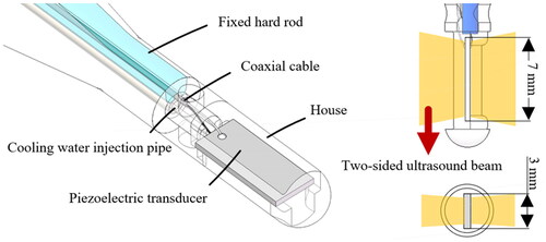
Table 1. Material properties of the ultrasound-based prototype catheter.
2.2. Frequency shift keying signal
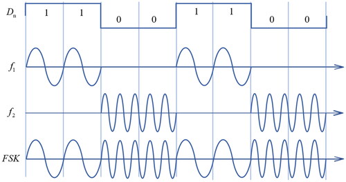
The driving signal is the sinusoidal wave, which is consisted by the two frequency’s signals alternated over time. The FSK modulation is given by [Citation43]
(1)
(1)
where Dn is the binary digital signal. The ω1 and ω2 are the different angular frequencies.
Mark frequency (Dn = 1) and space frequency (Dn = 0) are f1 and f2, respectively. The example of FSK signal is shown in . In this study, the mark frequency was 5.21 MHz, and the space frequency was 16.88 MHz. The pulse repetition frequency (PRF) of FSK signal was 1 Hz. The different harmonic duty cycle was realized by changing the binary digital signal
Figure 2. FSK modulation wave forms example.
2.3. Theoretical prediction
The essence of ultrasound thermal ablation can be summarized as irreversible thermal damage caused by ultrasound in tissue through reasonable control of ultrasonic energy. It is very important to understand the relationship between ultrasound dose and therapeutic effect. In order to achieve accurate ablation region and minimize the damage to nontarget tissue, the finite element analysis is used to calculate the sound field and the corresponding heat distribution in tissue. Simulation analysis of temperature rise can provide a reference for the optimal parameters of the ultrasound transducer. The bio-heat transfer equation for the simulation model of CBUS can be expressed as [Citation44]:
(2)
(2)
where ρ is the density of tissue (kg/m3), Cp is the specific heat capacity (J/kg/°C), k is the thermal conductivity of tissue (W/m·°C), T is the temperature of the biological tissue, ρb is the density of blood (kg/m3), Cb is the specific heat capacity of blood (J/kg/°C), ωb is the blood perfusion rate (1/s), Tb is temperature of blood (37 °C), Q is the external heat source (W/m3) and Qmet is metabolic heat generation (W/m3). In fact, metabolic heating is very small compared to ultrasound absorption. Therefore, the influence of metabolic heating is negligible. We can assume that the only heat source from the external is ultrasound, and metabolic heat generation is equal to zero.
The external ultrasonic heat source can be expressed as:
(3)
(3)
where I is the acoustic intensity (W/m2) which decay rapidly with increasing depth, α is the attenuation coefficient (Np/m), p is the pressure (Pa) and c is the speed of sound in tissue (m/s).
Pressure acoustics solves the wave equation in the medium surrounding the transducer. The wave equation describing the acoustic pressure distribution is:
(4)
(4)
where ρ0 is the fluid density (kg/m3), ω is the angular frequency (rad/s) and cs is the speed of sound (m/s).
The acoustic and thermal fields were analyzed by using COMSOL Multiphysics 5.6 (COMSOL Multiphysics5.6, Burlington, MA, USA). The model was used in the numerical simulations of the CBUS acoustic and thermal field is shown in . The material properties for the simulation model are listed in . The blood perfusion rate in hepatic tissue in our models is 6.4 × 10⁻³ 1/s [Citation45].
Figure 3. Schematic of the model used in the numerical simulation of the CBUS acoustic and thermal field.
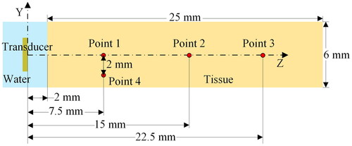
Table 2. The material parameters used for the simulations.
2.4. Acoustic characteristics test of ultrasound transducer
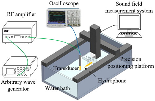
The frequency characteristics of the ultrasound transducer were measured before the experiment of thermal ablation, as the selection of an appropriate operating frequency is critical. The impedance analyzer (E4991A, Agilent Technologies-IES, Inc., USA) was used to measure the impedance curves of the transducer. The acoustic field distribution properties of the transducer were tested in an automatic three-dimensional (3D) sound field measurement system (UMS3, Precision Acoustics Ltd, Dorset, UK) as shown in . In the experiments, deionized and degasified water was used. The transducer was driven by a sinusoidal pulse signal with 10 cycles, 500 Hz PRF. The output sound pressure was calculated by converting the original voltage output received by needle hydrophones (NH0500, Precision Acoustics, Ltd, UK). The hydrophone was perpendicular to the surface of the transducer on the precision positioning platform (TS303, BOCIC, Ltd., China). Electrical power was measured by a power meter (RS-70, Nissei Co., Ltd., China). Sound power was measured by a radiative force balance (RFB, Precision Acoustics Ltd., USA).
Figure 4. Schematic of acoustic characteristic test.
2.5. Phantom and ex vivo test
The phantoms are fabricated based on a polyacrylamide gel mixed with egg white according to the normal method [Citation46]. It changes color at temperatures of around 60 °C and can be used as a temperature-sensitive indicator. An optimal egg white concentration of 30% (by mass) is satisfied for visualization of high intensity ultrasound exposure. The mixed solution consisted of 44.5% (volume in volume, v/v) degassed water, 30% (v/v) egg white, 24.8% (v/v) acrylamide (Macklin Biochemical Co., LTD., China), 0.5% (v/v) ammonium persulfate (Sinopharm Chemical Reagent Co., Ltd., China) and 0.2% (v/v) tetramethylethylenediamine (Macklin Biochemical Co., LTD., China). A special mold was designed to reserve multiple holes for the transducer to facilitate insertion. The mixed solution was then transferred into the mold to polymerize for 40–50 min. The different excitation sources of ultrasound transducer are compared with the thermal ablation areas in the phantoms.
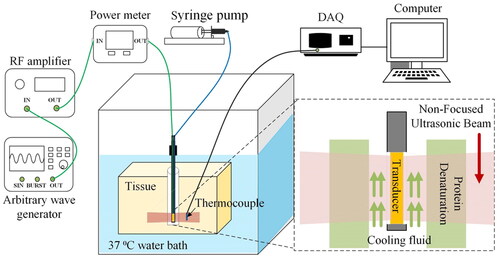
Phantom and ex vivo tests were performed to evaluate the therapeutic effect of FSK signals. The schematic of the tests is illustrated in . In the ex vivo tissue experiment, fresh pig liver was cut into small pieces with a size of about 75 × 70 × 40 mm. Phantom and fresh pig liver were placed at the bottom of a plastic water tank. The water temperature in the tank was maintained constant at 37 °C. The CBUS transducer was driven by the FSK signal generated by an arbitrary wave generator (DG1062, RIGOL Technologies, Inc., China) and then amplified by a radio frequency amplifier (150A100B, AR, Inc., USA). The transducer was excited by a continuous sine wave and electrical power was 20 W. The two frequencies of the FSK signal were 5.21 and 16.88 MHz, respectively. The signal generator was set as PRF of 1 Hz. The duty ratio of fundamental frequency (5.21 MHz) is 0, 25, 50, 75 and 100%, respectively. The temperature elevations and lesions in the phantom were measured by K-type thermocouples and photographs. The thermocouple was inserted into the four points in the phantom as shown in . Point 1, 2 and 3 are on the center line of 7.5, 15 and 22.5 mm, respectively. Point 4 is 7.5 mm away from the surface of the transducer and 2 mm away from the center line. Because the outer diameter of the thermocouple is small (0.2 mm), which is only 1/70 of the area of the sound field, the influence of the miniature thermocouple on the acoustic field was negligible. CBUS exposure persisted throughout the whole ablation process. A data acquisition unit was applied to sample the temperature at a rate of 2 Hz during the ablation process. After 60 and 180 s of ultrasound exposure, the sizes of the ablation areas were measured. To prevent transducer damage caused by heat collection, cooling water was injected at room temperature 25 °C at a rate of 10.0 ml/min in the experiments. Cooling water was injected through a cooling tube connected to the syringe pump (Xinka Electronic Products Co., Ltd., China). All ablation experiments were repeated three times for calculation of the mean and standard deviation. OriginPro (OriginLab, Northampton, MA, USA) was used for data analysis and figures.
Figure 5. Thermal ablation test setup in phantom and ex vivo.
3. Results
3.1. Acoustic characteristics of the transducer
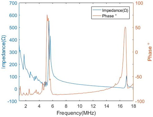
According to the impedance analysis results (), the fundamental frequency of the transducer was 5.21 MHz, and the third harmonic frequency was 16.88 MHz. Impedance values were about 35.0 and 15.4 Ω, respectively. The third harmonic frequency was slightly larger than three times the fundamental frequency. Previous work by Chopra et al. showed a similar phenomenon [Citation38]. And Onoe et al. concluded that the harmonic wave were slightly larger than three times the fundamental wave due to the influence of electromechanical coupling in the thickness mode resonator [Citation47]. The typical ultrasound frequency in the 3–12 MHz range has smaller wavelengths and higher absorption [Citation48]. The fundamental frequency is suitable for large radius (about 30 mm) ablation, and the third harmonic frequency is suitable for small radius ablation.
Figure 6. Impedance and frequency response curves of the ultrasound transducer.
The acoustic power was 10.03 and 6.19 W, respectively. The electroacoustic efficiencies of fundamental frequency and third harmonic frequency of the transducer are 50.1 and 30.6%, respectively. Similar conversion efficiencies were also obtained in previous studies [Citation39]. In spite of the lower electroacoustic conversion efficiency of the third harmonic frequency compared to the fundamental frequency, it is worthwhile to give up some energy to achieve more precise energy control by taking advantage of high frequency.
The acoustic pressure field for each resonant frequency of the transducer was measured in degassed water at room temperature by a needle hydrophone. The typical time-domain waveform of measured sound pressure is shown in . As the acoustic intensity gradually decreased with distance, considering that excessive sound intensity may cause damage to the hydrophone, acoustic parameters were measured at a distance of 15 mm away from the surface of the transducer, and the acoustic parameters on the surface of the transducer were higher than the measured values. The acoustic intensity and mechanical parameters of 5.21 and 16.88 MHz at 20 W of electrical power and 15 mm away from the transducer are shown in . The acoustic pressure of the third harmonic frequency was much lower than that of the fundamental frequency because the value of the attenuation of high frequency was larger. A diagram of the acoustic field is shown in and . The sound fields in the XOZ and YOZ planes were measured at 4.5 mm on the surface of the catheter, and the XOY plane was parallel to and 15 mm away from the transducer surface. Compared with the fundamental wave, the third harmonic wave has a wider distribution in the X-axis direction than the fundamental wave in the XOZ plane.
Figure 7. Time domain waveform of acoustic pressure (at 5.21 MHz, 80 Vpp, 10 bursts).
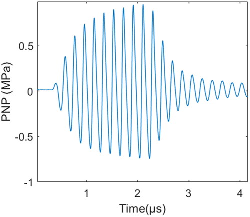
Figure 8. CBUS ablation catheter and sound field results. (a) CBUS ablation prototype catheter. (b) The spatial distribution diagram of the CBUS catheter in three orthogonal planes.
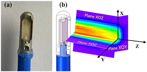
Figure 9. Acoustic field diagram measured with a needle hydrophone in degassed water. (a) The fundamental wave (5.21 MHz) and (b) the third harmonic wave (16.88 MHz).
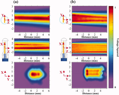
Table 3. Performances of the CBUS Transducer.
3.2. Simulation of acoustic and thermal field
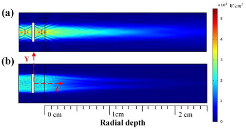
The simulation result of the acoustic intensity of the dual-frequency transducer with electric power set to 20 W is shown in . The ultrasound energy was concentrated in the direction of the transducer surface, and the outward diffusion of ultrasound energy was almost negligible. The sound intensity gradually decreased with the increase in the distance from the transducer surface. The simulation results show that the fundamental wave sound pressure field is concentrated within 1.5 mm, while the harmonic sound pressure field is concentrated within 2.5 mm in the Y-axis direction. In the sound pressure field measured by the YOZ plane (), the fundamental wave and the harmonic sound pressure fields are concentrated within 1 and 2 mm in the Y-axis direction, respectively. The fundamental wave acoustic pressure field is long and thin, while the harmonic wave acoustic pressure field is wide and short.
Figure 10. Simulation results for acoustic pressure field at (a) the fundamental wave resonance frequency (5.21 MHz) and (b) the third harmonic frequency (16.88 MHz).
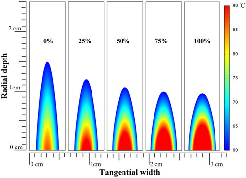
The simulation results for temperature elevation with various duty ratios of third harmonic frequency FSK signals (1/6 Hz PRF) at four points are shown in . The positions of the four points in the model are shown in . At a small radial depth along the Z-axis, the higher the duty ratio of the third harmonic was, the higher and faster the temperature rose (). The tendency was reversed at greater radial depths along the Z-axis (). The higher harmonic ratio resulted in a higher temperature rise in width along the Y-axis (). The simulation results for the thermal doses after ultrasound exposure using 0, 25, 50, 75 and 100% duty ratio of the third harmonic frequency are shown in . As the proportion of the third harmonic frequency increased, the ablation radial depth along the Z-axis decreased and the tangential width along the Y-axis increased. As a result, the third harmonic frequency can be adjusted to alter the ablation morphology.
Figure 11. Temperature elevation during the 3 min ultrasound exposure with different duty ratio of the third harmonic frequency at (a) 7.5 mm (point 1), (b) 15 mm (point 2), (c) 22.5 mm (point 3) away from the transducer surface and (d) 2 mm away from the center line (point 4).
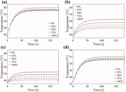
Figure 12. Prediction of the temperature distribution after 3 min of ultrasound exposed using 0%, 25%, 50%, 75% and 100% duty ratio of the third harmonic frequency (US settings of 20 W electric power, 1/6 Hz PRF, treatment 180 s).
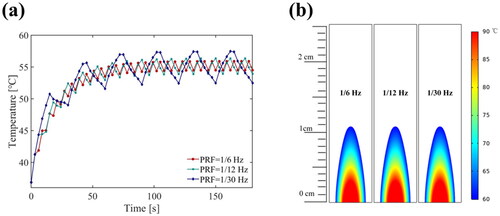
Further, we used simulation to evaluate the effect of the PRF of the FSK signal on heat ablation. Under the same electric power (20 W), simulation results for temperatures and the thermal dose with various PRF frequency FSK signals (50% duty ratio of the third harmonic) at point 2 are shown in . This result indicated that the influence of PRF value (PRF ≥ 1/30 Hz) on the temperature average value and the thermal dose could be ignored, and temperature curves were smoother with the higher PRF. In the phantom and ex vivo experiments, a high PRF (1 Hz) was applied. Since the computation time required for the simulation of a high PRF was greatly increased and the complexity of the computation procedure was too high, we did not simulate the higher PRF.
Figure 13. Simulation results at point 2 (15 mm away) for (a) the temperature elevation and (b) the temperature distribution with the various PRF conditions (US settings of 20 W electric power, 50% duty ratio of the third harmonic frequency, treatment 180 s).
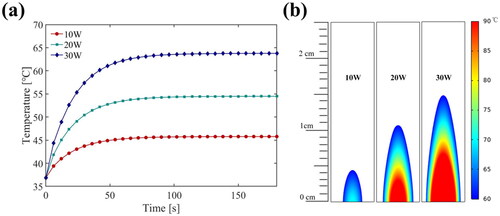
Finally, the thermal ablation doses at different electric power levels are shown in . Under the same duty ratio of the third harmonic (50%) and PRF (1/6 Hz), the temperature rises value and rate increased with the increase of electric power (). It was clearly observed that increasing electric power would increase the thermal ablation area without changing the morphology, as shown in .
Figure 14. Simulation results at point 2 (15 mm away) for (a) the temperature elevation and (b) the temperature distribution at electric power levers (US settings of 50% duty ratio of the third harmonic frequency, 1/6 Hz PRF, treatment 180 s).
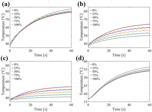
Due to the absence of blood perfusion in phantom and ex vivo experiments, the model is simulated without blood perfusion to evaluate its effect. The temperature curves of the four temperature measuring points during the 1 min ultrasound exposure in the model are shown in . Compared with the results of the simulations including blood perfusion (), blood perfusion slowed down the temperature rise rate to some extent.
Figure 15. Temperature transition during the 1 min ultrasound exposure with different duty ratio of the third harmonic frequency at (a) 7.5 mm (point 1), (b) 15 mm (point 2), (c) 22.5 mm (point 3) away from the transducer surface and (d) 2 mm away from the center line (point 4).
3.3. Phantom and ex vivo test results
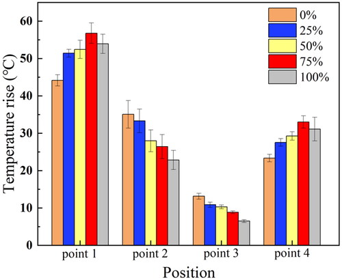
At four points in the same location as the simulation model in , all the harmonic duty ratio FSK signal excitations generated significantly different temperature curves (). The predictions of the temperature rise values using 20 W of applied electrical power for a period of 60 s are shown in . At point 1, the experimental group with a 100% harmonic ratio’s temperature rises to 89 °C, which is close to the simulation value (83 °C). The experimental groups with the high duty ratio of the third harmonic frequency had an advantage in the temperature at the smaller radial depth (7.5 mm) and larger tangential width (). For the larger radial depth two temperature measurement positions (15 and 22.5 mm), the temperature rise and rate were mainly determined by the duty ratio of the fundamental frequency (). The measured temperature curve () and the simulation results () are similar. In the simulation, although the temperature of the 75% group (80 °C) is less than that of the 100% group (83 °C), their effects are similar. In the experiment, the 75% experimental group experienced a higher temperature (92 °C) than the 100% experimental group (89 °C). The difference between simulation and experiment might be due to the error in measuring the temperature. In general, changing the duty ratio of the third harmonic frequency of FSK could control the rate of temperature rise.
Figure 16. Temperature curves measured in the gel phantom during 60 s CBUS exposure at (a) 7.5 mm (point 1), (b) 15 mm (point 2), (c) 22.5 mm (point 3) away from the transducer surface and (d) 2 mm away from the center line (point 4).
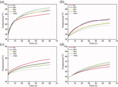
Figure 17. Temperature rise experiment results at different distances under the excitation of FSK signal with different harmonic duty ratios in gel phantom (standard deviation, n = 5 for all measurements, US settings of 20 W electric power, 1 Hz PRF, treatment 60 s).
The thermal lesions generated by 1 and 3 min ultrasound exposure with different FSK signal excitations in phantom are shown in . The maximum radial depths, tangential widths, and axial lengths of thermal lesions by 1 min ultrasound exposure are summarized in . The maximum radial depth is the maximum depth along the Z-axis. The maximum tangential width is the maximum width along the Y-axis. The maximum axial length is the maximum length along the X-axis. The maximum radial depth of the experiments varied from 31.7 ± 0.7 mm (n = 5) to 17.7 ± 0.5 mm (n = 5) with 0 and 100% duty ratio of the third harmonic frequency, respectively. The maximum tangential width was 1.8 ± 0.4 mm–8.1 ± 0.3 mm, respectively. The maximum axial length was 2.0 ± 0.3 mm–8.6 ± 0.6 mm, respectively. In addition, the lesions caused by the fundamental frequency were long, while those caused by the third harmonic frequency were tadpole shaped. It is significant to note that the shape of the thermal lesions generated by the ultrasound exposure with different FSK signal excitations changed. shows the lesions areas caused by 3 min of ultrasound exposure. Lesions caused by 3 min ultrasound exposure () were larger than lesions caused by 1 min ultrasound exposure (). In addition, their shapes were similar.
Figure 18. Photos of the phantom ablation induced by FSK signals with different harmonic ratios during CBUS exposures for 1 min and 3 min (a) representative top view photo by 1 min, (b) section view by 1 min, and (c) representative top view photo by 3 min, and (d) section view by 3 min.
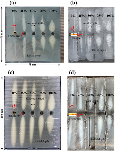
Table 4. Thermal lesions induced by various third harmonic frequency duty ratio in phantom (treatment 60 s, standard deviation, n = 5 for all measurements).
Table 5. Thermal lesions induced by various third harmonic frequency duty ratio in phantom (treatment 180 s, standard deviation, n = 3 for all measurements).
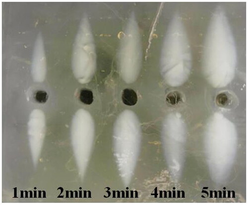
shows the lesions under third harmonic excitation with different ultrasound exposure times. As the action time increased from 1 to 5 min, the ablation area grew larger and the ablation morphology remained similar. As there was no blood perfusion in the phantom experiment, this may be due to the combined effect of ultrasound heating and heat conduction.
Figure 19. Under the third harmonic excitation, the discoloration region was observed at different ultrasound exposure times.
shows ex vivo tissue ablation stimulated by 1 and 3 min FSK signals with different harmonic ratios. The maximum radial depths, tangential widths and axial lengths of thermal lesions generated by 1 min of ultrasound exposure are shown in . depicts the ex vivo lesions caused by 3 min of CBUS exposure. The ablation size caused by 3 min of CBUS exposure is slightly larger than 1 min. The ablation areas generated by 3 min of ultrasound were analyzed with examples. Fundamental waves had a larger radial depth (26.2 vs. 11.0 mm), and harmonic waves had a larger axial length (11.3 vs. 9.2 mm). Compared with the fundamental wave (6.5 mm), the harmonic wave had a larger tangential width (9.3 mm). Ex vivo tests and simulations yielded similar results. According to the simulation results, the fundamental wave with a radial depth of 15 mm was deeper than the harmonic wave with a radial depth of 10 mm. Furthermore, as the harmonic ratio increased, the lesions became wider and shorter. These results indicated that FSK signal excitation with different harmonic ratios could change the ablation morphology and range. This result may be due to the alternation of the sound fields at two resonance frequencies and the different depositions of acoustic power in tissues. The results of radial depth, tangential width and axial length showed the same trend as those of the phantom test. However, the radial depth was obviously smaller than that of the phantom tests. It may be that there are more bubbles in the in vitro tissue, and the cavity in the area of the lesions obstructs the transmission of ultrasound. In general, the results of ex vivo tests had the same trend as those of simulation and phantom experiments.
Figure 20. Photos of the tissue ablation stimulated by FSK signals with different harmonic ratios in ex vivo by CBUS exposure of 1 min and 3 min. (a) Representative top view photo by 1 min, (b) section view by 1 min, and (c) representative top view photo by 3 min, and (d) section view by 3 min.
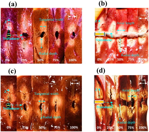
Table 6. Thermal lesions induced by different third harmonic frequency duty ratio in ex tissue (treatment 60 s, standard deviation, n = 3 for all measurements).
Table 7. Thermal lesions induced by different third harmonic frequency duty ratio in ex tissue (treatment 180 s, standard deviation, n = 3 for all measurements).
4. Discussion
CBUS ablation was limited in the shape of thermal lesions due to the constant acoustic field distribution in tumor treatment. In order to avoid the disadvantage of fixed sound field distribution with single frequency excitation during treatment, we proposed a simple and useful method for controlling the ablation morphology using FSK signal excitations. The problem caused by a single acoustic field could be effectively solved by combining the fundamental frequency and the third harmonic frequency with different duty ratios. The fundamental frequency sound field was relatively narrow and long, while the third harmonic frequency sound field was relatively wide and short. By combining these two frequencies, different acoustic power depositions were obtained to achieve different ablation morphologies under the conditions of the simple hardware system and the single planar transducer.
The acoustic characteristics of the dual-frequency transducer were analyzed by simulation and experiment. In this article, the dual-frequency transducer using both the fundamental and the third harmonic frequency generated two different acoustic fields. With the various harmonic ratios, the shape and size of thermal lesions changed.
In the phantom experiment, we reported the difference in ablation morphology in the experimental group. The shape of the lesion induced by 3 min of the fundamental wave was the long strip (47.8 × 6.8 × 7.5 mm), and the shape of the lesion induced by the harmonic wave was the droplet (29.7 × 10.3 × 10.2 mm). Ex vivo experiments (26.2 mm), phantom experiments (47.8 mm) and simulations (15.0 mm) revealed that the group with 0% harmonic ratio had the greatest radial depth of the ablation region. According to simulations (4.5 mm), phantom experiments (10.3 mm), and ex vivo experiments (9.3 mm), the experimental group with 100% harmonic ratio had the largest tangential width of the ablation region. For both phantom and ex vivo experiments, the axial length of ablation was longest in the 100% harmonic ratio experiment (10.2 and 11.3 mm, respectively). Nevertheless, the differences in the axial length (9.2–11.3 mm) and the tangential width (6.5–9.3 mm) of the ablation region were less pronounced in the ex vivo test. We hypothesized that there were more bubbles in the in vitro tissue, and the cavitation effect occurred in the thermal ablation process. In addition, the rapid near-field heating reduced the radial propagation of ultrasound by increasing the acoustic attenuation coefficient.
Compared with traditional CBUS devices with a single frequency transducer in previous studies [Citation21], the dual-frequency CBUS driven by the FSK signal has better ablation morphology control ability. The ablation area parallel to the transducer surface induced by conventional CBUS is slightly larger than the transducer area (10 × 3 mm). The radial depth is 15 mm in vitro experiments during 60 s CBUS exposure at 6 W acoustic power [Citation21]. When the input power and ultrasound exposure time remain unchanged, the shape of the lesion is a fixed droplet. The FSK signal with 0% harmonic ratio is the same as the single-frequency signal used in the traditional CBUS in our work. By contrast, the ablation area parallel to the direction of the transducer surface induced by 1 min of dual-frequency CBUS is controllable (from 5.7 mm × 5.2 mm to 8.3 mm × 7.3 mm). FSK signals can have a radial depth ranging from 10.7 to 23.0 mm dependent on their harmonic duty cycle. Despite constant input power and ultrasound time, lesions caused by the dual-frequency CBUS can differ in shape from strips to droplets. The dual-frequency CBUS can achieve more differences in morphology when compared to the traditional CBUS. Some CBUS devices with linear arrays of planar transducers provide more accurate ultrasound energy control, but they are more complex to implement [Citation18,Citation28].
There were some differences between the present and previous research on interventional ultrasound thermal ablation. First, dual-frequency excitation was performed at the fundamental frequency and the third harmonic frequency in this study, while a single frequency was used in most existing studies. Although some studies showed that multifrequency can improve cavitation effect and thrombolysis efficiency, these studies are mostly carried out on multiple HIFU transducers [Citation35]. Suo et al. reported that dual- and triple-frequency amplitude modulation signals were applied in one transducer in thrombolysis [Citation49], which were different from the FSK signals adopted in this article. Second, compared with the widely used HIFU (about 80 W) [Citation50], this study used lower electrical power (20 W). The CBUS was more efficient in tissue lesions, which could be potentially extrapolated to clinical applications. In similar CBUS studies, with the same electrical power, our treatment was more efficient than forward-looking and tubular transducers [Citation51,Citation52]. As the lesion volume caused by the forward-looking transducer remains within the range [Citation51]. And compared with cylindrical transducers, planar transducers had more efficiency in the volumetric lesion [Citation52]. A larger ablation range can be achieved by applying our method to rotational or translational mechanical platforms. Third, FSK signals with different duty cycles were studied and the influence on ablation morphology was evaluated.
This study still needs to be improved and perfected. For example, compared with most interventional ultrasound thermal ablation studies, the size of our transducer is slightly larger (7 × 3 mm), and its application is limited to a certain extent. The sound field of the planar transducer is mainly concentrated in front of the transducer surface, while the sound field of the annular transducer is divergent and more evenly distributed in the transverse direction. In order to simplify the experiments, most of the experiments were carried out in gel phantoms and ex vivo. Nevertheless, in actual biological tissue, the influence of blood perfusion needs to be considered. Thermal conduction does not necessarily lead to bigger zones, due to blood perfusion and other heatsink effects in living tissue. Blood perfusion in living tissues may affect ablation morphology.
Referring to previous studies on cavitation effects, it can be concluded that both dual-frequency, pseudorandom signals and frequency sweeps are likely to affect cavitation [Citation31]. In future studies, we will try to explore the influence of these factors on the thermal effect. Other modulation signals, such as binary Golay coded, amplitude modulation and phase modulation need more investigation. Due to the lack of live animal experiments in this article, our future work will include in vivo experiments in large heat sink organs.
Despite the limitations of the current technology, this study proved that FSK signals with different harmonic ratios induced different shapes and sizes of tissue thermal lesions with a relatively low input power of only 20 W. In addition, phantom and ex vivo test results verified the effectiveness of the method. It is potential for ultrasound precision ablation technology in the future as it can significantly reduce the risk of accidental tissue damage. Combined with the existing rotational and translational mechanical devices, the dual-frequency transducer driven by the FSK signal could have application in prostate cancers, brain tumors and non-resectable liver tumors.
5. Conclusions
In this work, a simple and effective FSK signal was proposed for dual-frequency transducers to improve the ablation precision and the efficiency of thermal ablation in the target area. Precise ablation is achieved by applying an appropriate harmonic duty cycle to control the ablation morphology and optimize the thermal deposition of the target region. Simulations and experiments showed that the dual-frequency transducer had different sound field distributions under the excitation of two resonant frequencies. The numerical simulation results revealed that FSK signals could produce various temperature fields. In both the phantom and ex vivo, the areas of thermal lesions changed with FSK signals. With a high harmonic duty cycle, shallower and wider ablation areas were achieved. While the deeper and narrower ablation was produced by a low harmonic duty cycle of FSK signals. The method solves the problem of the fixed lesion shapes produced by traditional CBUS devices with a single frequency transducer. The FSK signals show better performance than the traditional single frequency excitation in controlling the ablation area. In summary, various morphologies of lesions can be achieved by controlling the harmonic ratio of the FSK signal. In the future, this work will play a significant role in precise tissue ablation.
Acknowledgments
The authors thank Mr. Jiabing Lv for his helps in the simulations. And the authors also thank Miss Wenjia Lu for transducers testing. Thanks to all funds that supported this project.
Disclosure statement
No potential conflict of interest was reported by the author(s).
Additional information
Funding
References
- Johnson DE, Cromeens DM, Price RE. Interstitial laser prostatectomy. Lasers Surg Med. 1994;14(4):299–305.
- Lancaster C, Toi A, Trachtenberg J. Interstitial microwave thermoablation for localized prostate cancer. Urology. 1999;53(4):828–831.
- Hildebrand P, Kleemann M, Roblick UJ, et al. Radiofrequency-ablation of unresectable primary and secondary liver tumors: results in 88 patients. Langenbecks Arch Surg. 2006;391(2):118–123.
- Diederich CJ. Thermal ablation and high-temperature thermal therapy: overview of technology and clinical implementation. Int J Hyperthermia. 2005;21(8):745–753.
- Keane MG, Bramis K, Pereira SP, et al. Systematic review of novel ablative methods in locally advanced pancreatic cancer. WJG. 2014;20(9):2267–2278.
- Diederich CJ. Ultrasound applicators with integrated catheter-cooling for interstitial hyperthermia: theory and preliminary experiments. Int J Hyperthermia. 1996;12(2):279–297.
- Bailey MR, Khokhlova VA, Sapozhnikov OA, et al. Physical mechanisms of the therapeutic effect of ultrasound—(a review). Acoust Phys. 2003;49(4):369–388.
- Sanghvi NT, Fry FJ, Bihrle R, et al. Noninvasive surgery of prostate tissue by high-intensity focused ultrasound. IEEE Trans Ultrason Ferroelectr Freq Control. 1996;43(6):1099–1110.
- Izadifar Z, Izadifar Z, Chapman D, et al. An introduction to high intensity focused ultrasound: systematic review on principles, devices, and clinical applications. JCM. 2020;9(2):460.
- Qian K, Li C, Ni Z, et al. Uniform tissue lesion formation induced by high-intensity focused ultrasound along a spiral pathway. Ultrasonics. 2017;77:38–46.
- Tu J, Hwang JH, Chen T, et al. Controllable in vivo hyperthermia effect induced by pulsed high intensity focused ultrasound with low duty cycles. Appl Phys Lett. 2012;101(12):124102.
- Tu J, Yu AC. Ultrasound-mediated drug delivery: sonoporation mechanisms, biophysics, and critical factors. BME Front. 2022;2022:1–17.
- Li P, Huang W, Xu J, et al. Efficacy estimation of microbubble-assisted local sonothrombolysis using a catheter with a series of miniature transducers. Micromachines. 2021;12(6):612.
- Yang CP, Li Y, Du M, et al. Recent advances in ultrasound-triggered therapy. J Drug Target. 2019;27(1):33–50.
- N’Djin WA, Mougenot C, Kobelevskiy I, et al. Dual-frequency ultrasound focal therapy for MRI-Guided transurethral treatment of the prostate: study in gel phantom. In: AIP Conference Proceedings; Heidelberg, Germany; 2012. p. 212–216.
- Chopra R, Baker N, Choy V, et al. MRI-compatible transurethral ultrasound system for the treatment of localized prostate cancer using rotational control. Med Phys. 2008;35(4):1346–1357.
- Salgaonkar VA, Diederich CJ. Catheter-based ultrasound technology for image-guided thermal therapy: current technology and applications. Int J Hyperthermia. 2015;31(2):203–215.
- Adams MS, Diederich CJ. Deployable cylindrical phased-array applicator mimicking a concentric-ring configuration for minimally-invasive delivery of therapeutic ultrasound. Phys Med Biol. 2019;64(12):20.
- Bouchoux G, Owen NR, Chavrier F, et al. Interstitial thermal ablation with a fast rotating dual-mode transducer. IEEE Trans Ultrason Ferroelectr Freq Control. 2010;57(5):1086–1095.
- Bessiere F, N'Djin WA, Colas EC, et al. Ultrasound-guided transesophageal high-intensity focused ultrasound cardiac ablation in a beating heart: a pilot feasibility study in pigs. Ultrasound Med Biol. 2016;42(8):1848–1861.
- Couppis A, Damianou C, Kyriacou P, et al. Heart ablation using a planar rectangular high intensity ultrasound transducer and MRI guidance. Ultrasonics. 2012;52(7):821–829.
- Nazer B, Salgaonkar V, Diederich CJ, et al. Epicardial catheter ablation using high-intensity ultrasound: validation in a swine model. Circ Arrhythmia Electrophysiol. 2015;8(6):1491–1497.
- Nazer B, Giraud D, Zhao Y, et al. High-intensity ultrasound catheter ablation achieves deep mid-myocardial lesions in vivo. Heart Rhythm. 2021;18(4):623–631.
- Canney MS, Chavrier F, Tsysar S, et al. A multi-element interstitial ultrasound applicator for the thermal therapy of brain tumors. J Acoust Soc Am. 2013;134(2):1647–1655.
- Ghoshal G, Gee L, Heffter T, et al. A minimally invasive catheter-based ultrasound technology for therapeutic interventions in brain: initial preclinical studies. Neurosurg Focus. 2018;44(2):E13.
- Liu D, Adams MS, Diederich CJ. Endobronchial high-intensity ultrasound for thermal therapy of pulmonary malignancies: simulations with patient-specific lung models. Int J Hyperthermia. 2019;36(1):1108–1121.
- Nau WH, Diederich CJ, Burdette EC. Evaluation of multielement catheter-cooled interstitial ultrasound applicators for high-temperature thermal therapy. Med Phys. 2001;28(7):1525–1534.
- Owen NR, Bouchoux G, Murillo-Rincon A, et al. Dual-mode 5-element transducer for image-guided interstitial ultrasound therapy: in vitro evaluation. In: AIP Conference Proceedings; Minneapolis, MN; 2009. p. 347-+.
- Owen NR, Chapelon JY, Bouchoux G, et al. Dual-mode transducers for ultrasound imaging and thermal therapy. Ultrasonics. 2010;50(2):216–220.
- Coussios CC, Farny CH, Haar GT, et al. Role of acoustic cavitation in the delivery and monitoring of cancer treatment by high-intensity focused ultrasound (HIFU). Int J Hyperthermia. 2007;23(2):105–120.
- Hallez L, Lee J, Touyeras F, et al. Enhancement and quenching of high-intensity focused ultrasound cavitation activity via short frequency sweep gaps. Ultrason Sonochem. 2016;29:194–197.
- Ma J, Guo S, Wu D, et al. Design, fabrication, and characterization of a single-aperture 1.5-MHz/3-MHz dual-frequency HIFU transducer. IEEE Trans Ultrason Ferroelect Freq Control. 2013;60(7):1519–1529.
- Guo S, Jiang X, Lin W, et al. Tissue ablation using multi-frequency focused ultrasound. In: IEEE International Ultrasonics Symposium; 2011 Oct 18–21; Orlando, FL; 2011. p. 2177–2180.
- Suo DJ, Govind B, Zhang SQ, et al. Numerical investigation of the inertial cavitation threshold under multi-frequency ultrasound. Ultrason Sonochem. 2018;41:419–426.
- Guo S, Jing Y, Jiang X. Temperature rise in tissue ablation using multi-frequency ultrasound. IEEE Trans Ultrason Ferroelectr Freq Control. 2013;60(8):1699–1707.
- Wang M, Zhou Y. High-intensity focused ultrasound (HIFU) ablation by frequency chirp excitation: reduction of the grating lobe in axial focus shifting. J Phys D Appl Phys. 2018;51(28):285402.
- Wang M, Lei Y, Zhou Y. High-intensity focused ultrasound (HIFU) ablation by the frequency chirps: enhanced thermal field and cavitation at the focus. Ultrasonics. 2019;91:134–149.
- Chopra R, Luginbuhl C, Foster FS, et al. Multifrequency ultrasound transducers for conformal interstitial thermal therapy. IEEE Trans Ultrason Ferroelectr Freq Control. 2003;50(7):881–889.
- N’Djin WA, Burtnyk M, Bronskill M, et al. Investigation of power and frequency for 3D conformal MRI-controlled transurethral ultrasound therapy with a dual frequency multi-element transducer. Int J Hyperthermia. 2012;28(1):87–104.
- N’Djin WA, Burtnyk M, Kobelevskiy I, et al. Coagulation of human prostate volumes with MRI-controlled transurethral ultrasound therapy: results in gel phantoms. Med Phys. 2012;39(7):4524–4536.
- Ramsay E, Mougenot C, Staruch R, et al. Evaluation of focal ablation of magnetic resonance imaging defined prostate cancer using magnetic resonance imaging controlled transurethral ultrasound therapy with prostatectomy as the reference standard. J Urol. 2017;197(1):255–261.
- Li J, Ma Y, Zhang T, et al. Recent advancements in ultrasound transducer: from material strategies to biomedical applications. BME Front. 2022;2022:1–19.
- Indriyanto S, Edward IYM. Ultrasonic underwater acoustic modem using frequency shift keying (FSK) modulation. In: 2018 4th International Conference on Wireless and Telematics (ICWT); 2018 Jul 12–13; Nusa Dua, Bali, Indonesia; 2018.
- Pennes HH. Analysis of tissue and arterial blood temperatures in the resting human forearm (Reprinted from Journal of Applied Physiology, vol 1, pg 93–122, 1948). J Appl Physiol. 1998;[85(1):5–34.
- Tungjitkusolmun S, Staelin T, Haemmerich D, et al. Three-dimensional finite-element analyses for radio-frequency hepatic tumor ablation. IEEE Trans Biomed Eng. 2002;49(1):3–9.
- Takegami K, Kaneko Y, Watanabe T, et al. Polyacrylamide gel containing egg white as new model for irradiation experiments using focused ultrasound. Ultrasound Med Biol. 2004;30(10):1419–1422.
- Onoe M, Tiersten HF, Meitzler AH. Shift in the location of resonant frequencies caused by large electromechanical coupling in thickness-mode resonators. J Acoust Soc Am. 1963;35(1):36–42.
- Prakash P, Salgaonkar VA, Diederich CJ. Modelling of endoluminal and interstitial ultrasound hyperthermia and thermal ablation: applications for device design, feedback control and treatment planning. Int J Hyperthermia. 2013;29(4):296–307.
- Suo D, Guo S, Lin W, et al. Thrombolysis using multi-frequency high intensity focused ultrasound at MHz range: an in vitro study. Phys Med Biol. 2015;60(18):7403–7418.
- Huang CW, Sun MK, Chen BT, et al. Simulation of thermal ablation by high-intensity focused ultrasound with temperature-dependent properties. Ultrason Sonochem. 2015;27:456–465.
- Kim H, Wu H, Cho N, et al. Miniaturized intracavitary forward-looking ultrasound transducer for tissue ablation. IEEE Trans Biomed Eng. 2020;67(7):2084–2093.
- Adams MS, Scott SJ, Salgaonkar VA, et al. Thermal therapy of pancreatic tumours using endoluminal ultrasound: parametric and patient-specific modelling. Int J Hyperthermia. 2016;32(2):97–111.