
Abstract
Purpose
To characterize the coagulation zones created by two radiofrequency (RF)-based hemostatic devices: one comprised an internally cooled monopolar electrode and the other comprised externally irrigated bipolar electrodes (saline-linked).
Materials and methods
RF-induced coagulation zones were created on ex vivo and in vivo porcine models. Computer modeling was used to determine the RF power distribution in the saline-linked device.
Results
Both external (irrigation) and internal cooling effectively prevented tissue sticking. Under ex vivo conditions in ‘painting’ application mode, coagulation depth increased with the applied power: 2.8 − 5.6 mm with the 3-mm monopolar electrode, 1.6 − 6.0 mm with the 5-mm monopolar electrode and 0.6 − 3.2 mm with the saline-linked bipolar electrodes. Under in vivo conditions and using spot applications, the 3-mm monopolar electrode created coagulation zones of similar depth to the saline-linked bipolar electrodes (around 3 mm), while the 5-mm monopolar electrode created deeper coagulations (4.5 − 6 mm) with less incidence of popping. The presence of saline around the saline-linked bipolar electrodes meant that a significant percentage of RF power (50 − 80%) was dissipated by heating in the saline layer. Coagulation zones were histologically similar for all the tested devices.
Conclusions
Both external (irrigation) and internal cooling in hemostatic RF devices effectively prevent tissue sticking and create similar coagulation zones from a histological point of view. Overall, saline-linked bipolar electrodes tend to create shallower coagulations than those created with an internally cooled monopolar electrode.
1. Introduction
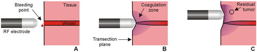
Radiofrequency (RF)-based hemostatic devices are normally used during surgery to reduce intraoperative blood loss. These devices apply electrical RF power (∼350 kHz) at a relatively low voltage (<200 V) and high current (1 − 2 A) (root-mean-square values). Depending on whether the mode of operation is monopolar or bipolar, one or two electrodes are placed in contact with the target tissue, respectively. According to the biophysical principle that applies to any of these devices, applying RF current raises the tissue temperature, which causes a localized coagulative necrosis and the collapse of small and medium-sized blood vessels on the transection plane (see ). While it is reasonable to assume that the deeper the coagulation zone, the greater the sealing capacity (especially in medium-sized vessels), it is also feared that deep coagulation may damage delicate adjacent structures, so that predicting the coagulation depth is essential in terms of efficacy and safety. According to the biophysics of RF heating, the size of the coagulation zone is known to depend on the electrode size, tissue contact surface, applied power and duration. This leaves the responsibility for programming a specific energy setting in the hands of the surgeon according to the target to be coagulated at any time during the procedure and the specific model of the device.
Figure 1. Sealing mechanism of an RF electrode used as hemostatic device during surgery. The electrode is placed on the bleeding point (A) and the applied RF current creates a coagulation zone that involves shrinkage of the tissue and vessel sealing (B). In the context of surgical oncology, RF-based hemostatic devices can also be used to ablate the surface of the remnant organ to increase the tumor-free margin and minimize local recurrence (C).
The Aquamanty® device (Medtronic, Portsmouth, NH) is a currently employed RF-based sealer based on two externally cooled (irrigated) electrodes that has been clinically used in pancreas [Citation1], brain [Citation2], orthopedic [Citation3] and liver surgery [Citation4]. RF power is applied in bipolar mode between these electrodes so that no dispersive electrode is needed (). The Coolingbis® device (Vecmedical, Barcelona, Spain) has a different design based on an internally-cooled monopolar electrode (). This device was originally developed by Apeiron Medical (Valencia, Spain) under the brand name of Coolinside®. To date, it has been clinically used in liver [Citation5,Citation6], spleen [Citation7] and pancreas [Citation8] surgery. Both devices incorporate cooling in the electrodes to keep the temperature low and avoid tissue sticking. However, while in the external irrigation of the Aquamanty® device the saline leaves the electrode through small holes and thus creates a conductive liquid layer on the tissue, the internally cooled Coolingbis® device is based on a closed circuit which prevents the saline from reaching the surgical field, while the RF power application mode (monopolar or bipolar) also determines the electro-thermal behavior and therefore the size of the coagulation zone.
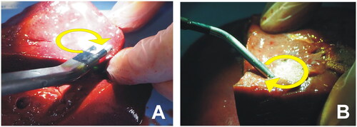
Figure 2. RF-based electrodes for surgical sealing (ex vivo set up). (A) Aquamantys® device (Medtronic, Portsmouth, NH) based on two externally cooled (irrigated) electrodes. (B) Coolingbis® device (Vecmedical, Barcelona, Spain) based on an internally-cooled monopolar electrode. Both devices can create coagulation zones either by moving the device over the tissue (‘painting motion’) or by keeping it fixed on a bleeding point, as shown in . In the first case, RF power was applied with the device slightly inclined to the tissue surface in a continuous circular motion (2.5 cm diameter, ∼1 turn/s) (see yellow arrows).
In the context of surgical oncology, RF-based hemostatic devices can also ablate the surface of the remnant organ to increase the tumor-free margin and affect local recurrence [Citation5,Citation6,Citation9] (). Theoretically, the deeper the coagulation zone, the greater the tumor-free margin. The bipolar mode is known to create shallower coagulations than the monopolar mode, since the RF current flows through the tissue very superficially. In fact, the capacity of monopolar electrodes, such as the Coolingbis® device, to create deeper coagulations has been argued as a disadvantage, for instance in case of cirrhotic patients or during resection in a living donor liver transplant since a greater amount of hepatic tissue is sacrificed [Citation10]. However, our hypothesis is that the coagulation depth will mainly depend on the programmed power, so that monopolar electrodes should also be able to create shallow coagulations if the programmed power is low enough. Although there are clinical data suggesting that both devices are effective and safe during surgery, preclinical studies based on ex vivo and in vivo models are necessary to compare the coagulation ability of each device. As far as we know, there are no data available on the coagulation depth created with the Aquamantys® and Coolingbis® devices at different power levels so that our objective was to characterize the coagulation zones created with both devices in ex vivo and in vivo porcine models.
2. Materials and methods
2.1. Devices under test
Two models of the Coolingbis® device were considered: BIS-3C01 and BIS-5C01 (the difference between them being the rounded-tip electrode outer diameter, 3 and 5 mm, respectively). The Coolingbis® device was connected to the Apeipower generator, which can program nine power levels, equivalent to peak voltages ranging from 145 (level 1) to 245 V (level 9), which means that the power actually applied is dependent on tissue impedance (with a 200 W power limit). This constant voltage mode reduces the power when the tissue becomes too dehydrated, which is an advantage in terms of control and safety. It also gives the surgeon versed in RF ablative techniques greater versatility, since the power actually applied can be easily modulated by varying the electrode-tissue contact surface: a larger contact area means lower tissue impedance and, therefore, higher applied power, and vice versa. The internal cooling of the electrode was by 0.9% NaCl at 10 °C and a flow rate of ∼200 ml/min using a peristaltic pump model Cool-tip RF System (Radionics, Burlington, MA).
One model of the Aquamantys® device was considered: the 6.0 Bipolar Sealer, consisting of two 3.5 mm diameter rounded-tip electrodes with external irrigation holes for 0.9% NaCl at room temperature. A low flow irrigation rate (∼2.5 ml/mim) was programmed since medium and high rates create small coagulation zones, possibly due to the RF current being preferentially shunted through the saline itself. The Aquamantys® device was connected to its own generator, which also includes a peristaltic pump. The applied power can be programmed from 20 to 200 W.
2.2. Ex vivo model
Fragments of pig liver were obtained within 24 h of sacrifice and warmed to room temperature (21 °C). The fragments were placed on a metal plate to close the RF circuit in the monopolar application (Coolingbis® device). Both the Coolingbis® and Aquamantys® devices were tested by simulating two typical surgical maneuvers: (1) a ‘painting motion’ on a resection margin, and (2) a spot application on a bleeding point [Citation11]. In the first scenario, RF power was applied with the device slightly inclined to the tissue surface while a continuous circular motion (2.5 cm diameter, ∼1 turn/s) was described by Topp et al. [Citation12] (see ). A plastic marker was placed just before each RF application to create a path and guide the circular motion. In the second scenario, RF power was applied by keeping the device fixed on the same site, i.e., without moving. All the applications were for 10 s, which we considered to be a reasonable time to manage a bleeding point during a surgical procedure.
Each device was connected to its corresponding RF generator. In the case of the Aquamantys®, the power varied from a minimum value of 20 W up to a value associated with the noticeable appearance of audible steam popping, which occurs when the temperature in the subsurface rises above 100 °C, leading to steam formation and expansion, which can cause disruption of the surface [Citation12]. We are assuming that this condition is an undesirable side effect since it cannot ensure effective closure of the vessels. In fact, if power is increased further, the coagulation zone could be too shallow and have a charred surface, with the consequent risk of late bleeding. In the case of the Coolingbis®, the power levels were changed from 1 to 9 using the Apeipower generator or until the notable incidence of steam pops (whichever happened first).
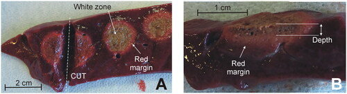
In both devices, the tested power range was lower in when the electrode was moved in circles, since spot-application involves overheating by applying too much power on the same site. Five coagulations were conducted for each power value on zones as homogenous as possible, i.e., avoiding large-size vessels, and never on the Glisson’s capsule because (1) the application of RF on the intact capsule causes the appearance of steam between liver parenchyma and capsule, with the subsequent explosion and surface cratering and (2) the device is aimed to coagulate the transections plane, where there is no capsule. The usual surgical maneuver involves applying RF to the transection plane, i.e., without a capsule. During each RF application the appearance of smoke, steam popping, bubbles on the tissue surface, electrode sticking and charring were assessed and quantified using a five-point scale: none (o), very little (+), some (++), much (+++), very much (++++). Steam popping was characterized by a sudden audible explosion, which did not necessarily disrupt the surface or create a crater, as described by Topp et al. [Citation12] (possibly because our criterion was more conservative and was really an early sign of disruption and cratering). After the coagulation, the tissue was cut (see ), to measure the depth of the coagulation zone using a caliper (see ). Each measurement was independently conducted by the two operators (FB, EB) by considering the whitish zone of the tissue, i.e., excluding the red margin (hemorrhagic rim).
Figure 3. Examples of coagulations zones created with the Coolingbis® device on ex vivo samples. (A) Top view of the tissue surface (i.e., transection plane) showing circular coagulations zones created after moving the electrode during RF application. Only the whitish zone was considered in the measurement of the size, discarding the red margin. (B) Side view of the cut tissue. Depth was measured from the tissue surface.
2.3. In vivo model
We repeated the spot application experiments (5 repetitions/power level) on an in vivo porcine liver model based on a Landrace pig weighing 92 kg, which was the final part of another study in which an RF device was tested on the pancreas. The in vivo part of this study was performed prior to necropsy and pancreas extraction. All the aspects of this study were performed as part of an animal research protocol, in accordance with the guidelines approved by the Ethical Commission of the Universitat Autònoma de Barcelona (Authorization Number CEEAH 3487 and DMAH 9583) and the Government of Catalonia’s Animal Care Committee.
Preoperative care and anesthesia were provided by fully trained veterinary staff. The animal was fasted for 12 h before surgery. After initial intramuscular sedation with a combination of azaperone (4 mg/kg), ketamine (10 mg/kg) and midazolam (0.2 mg/kg), intravenous access was obtained through marginal ear-vein cannulation. Analgesia was given previous to general anesthesia (morphine 0.2 mg/kg IV). The anesthetic induction phase was performed with propofol (4 mg/kg IV). The trachea was intubated and anesthesia maintained with 2–2.5% isoflurane IsoVet (B. Braun VetCare Spain, Rubí, Spain) in 100% oxygen through a semi-closed circular anesthetic system. Ventilation was controlled using a SAV 2500 intermittent positive pressure ventilator (B. Braun VetCare Spain, Rubí, Spain) to maintain normocapnia during the entire anesthetic period. An infusion of lactated Ringer’s solution was administered at a rate of 10 ml/kg/h during the perioperative period via the auricular vein. Temperature, cardiac frequency, respiratory frequency, capnography, arterial pressure, pulse and electrocardiography were monitored throughout the surgical process by a patient VetCare multifunction monitor (B. Braun VetCare Spain, Rubí, Spain).
The surgical procedure was as follows. The animals’ abdomen was prepared aseptically. The liver was exposed through an exploratory laparotomy and isolated using gauzes moistened with sterile physiological serum. RF coagulations were performed on the left lateral and medial and on the right medial liver lobes. Prior to RF application, the Glisson’s capsule was removed by a surgical scissors and trying to damage the parenchyma as little as possible. Once the coagulations were finished, the pig was euthanized with pentobarbital sodium (200 mg/kg IV). During necropsy, coagulated liver specimens were dissected and the whitish zone was measured in depth, excluding the red margin. Three samples were collected for the histopathological study from each device under test, including coagulated tissue and surrounding normal liver. Specimens were 10% formalin-fixed, routinely processed and paraffin embedded. Five μm sections were obtained and stained with Hematoxylin & Eosin (H&E). Slides were digitized using the Nanozoomer 2.0HT scanner (Hamamatsu Photonics, Hamamatsu City, Japan), and the viewer software (Hamamatsu NDP.view2), was used to characterize the different coagulation zones and measure the coagulation depth.
2.4. In-silico modeling
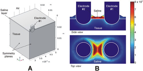
An in-silico model was used to estimate the electric power targeted onto the tissue with the Aquamantys® device, since its design allows for the presence of a thin saline layer on the tissue which forms a leak path for the RF current. In contrast, as the Coolingbis® devices do not use external saline, 100% of the distributed RF power is effectively applied to the tissue. We assumed that the Aquamantys® device was perpendicular to the tissue surface, with the electrodes (3.5 mm diameter) inserted 1.25 mm into the tissue. We considered a 0.5 mm saline layer covering the entire surface of the tissue, and a thicker layer (up to 1 mm) in the vicinity of the electrode to simulate the saline infusion through the orifices, as in Arenas et al. [Citation13] (see ). The physical setting has two symmetry planes, so that the model can be simplified to a quarter of the full volume (see ). To simulate a 20 W application, quarter power was applied (52 V at a tissue impedance of 528 Ω). The power density was calculated by solving the Laplace equation with COMSOL Multiphysics software (COMSOL, Burlington, MA). We also assessed the effect of changing the saline layer from 0.5 to 3.0 mm, and the electrode insertion depth from 0.75 to 2.75 mm.
Figure 4. In-silico modeling of the Aquamantys device. (A) Geometry of the ¼ scale 3D model using two symmetry planes. (B) Electrical power density (in W/m3) deposited in saline and tissue at 20 W power.
The mesh size was predefined on Comsol using a Physics-controlled mesh in mesh settings. We used a normal element size with the following characteristics: 2.9 mm maximum size, 0.522 mm minimum size and maximum element growth rate 1.5. The mesh was automatically refined around the electrodes and saline layer, where the maximal electric gradient can be expected. A mesh size sensitivity study was performed to find the proper spatial discretization and minimize its effect on the numerical solution. We used the electrical power density (in W/m3) at different points around the electrode and saline (spaced 0.5 mm) as reference parameter, avoiding singular points where the mesh refinement results in an infinite increase in the electrical power density value. We considered the normal element size as appropriate, since differences in the reference parameter were less than 0.5% between normal and fine (the next finer mesh option) using an adaptively changing time step. We also assessed the suitability of the time step and other dimensions by the same type of sensitivity analysis.
2.5. Statistical analysis
Linear and non-linear regression models were performed to determine the best-fit equations for coagulation depth. The model’s goodness of fit a model was individually assessed by R2 (coefficient of determination) for each group, which can be interpreted as the proportion of the total variability explained by the model. Differences with a value of p < 0.05 were considered to be statistically significant. All the data were handled and analyzed on IBM SPSS Statistics for Windows version 25.0 (IBM, Armonk, NY).
3. Results
3.1. Ex vivo results
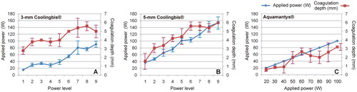
and show the characteristics of the coagulation zones created on ex vivo liver using a ‘painting motion’ with the 3 and 5 mm Coolingbis® devices, respectively. No sticking occurred in any case. The real power applied was significantly higher with the 5-mm electrode for the same power level programmed in the generator. As the power level increased, the coagulations with the 3-mm electrode exhibited more superheating than the 5-mm electrode, with more bubbling, smoking, popping and charring. Coagulation depth increased with the programmed power level, with the 5-mm electrode showing a wider range (from 1.6 ± 0.9 to 6.0 ± 0.0 mm) than the 3-mm (from 2.8 ± 0.4 to 5.0 ± 0.7 mm). shows the characteristics of the coagulation zones created on ex vivo liver using the ‘painting motion’ with the Aquamantys® device. No sticking happened in any case. Coagulations were characterized by continuous saline bubbling around the electrodes. Coagulation depth increased with the applied power from 0.6 ± 0.2 to 3.2 ± 0.4 mm.
Table 1. Characteristics of the coagulations created ex vivo with the Coolingbis® device (3 mm electrode) in ‘painting motion’ mode (n = 5 applications per level power).
Table 2. Characteristics of the coagulations created ex vivo with the Coolingbis® device (5 mm electrode) in ‘painting motion’ mode (n = 5 applications per level power).
Table 3. Characteristics of the coagulations created ex vivo with the Aquamantys® device in ‘painting motion’ mode (n = 5 applications per level power).
summarizes the applied power and coagulation depth data shown in . The coagulation depth/applied power ratio was calculated for each device. This ratio could be considered a possible metric of heating efficiency. Each device behaved differently. In the 3-mm Coolingbis® device, the ratio progressively decreased with increasing programmed power level, from 0.18 mm/W (at level 1) to 0.06 mm/W (at level 9). In the 5-mm Coolingbis® device, the ratio was practically independent of the power level, with values around 0.04 − 0.07 mm/W. The Aquamantys® device showed the lowest values, between 0.02 and 0.04 mm/W, also relatively independent of the applied power.
Figure 5. Applied power (blue) and coagulation zone depths (red) created by the Coolingbis® and Aquamantys® devices on ex vivo pig liver in ‘painting’ application mode. In the case of the Colingbis® device the applied power is impedance-dependent, for which the applied power is also plotted. The data (mean and standard deviation) are from .
shows the characteristics of the coagulation zones created on ex vivo liver using spot application with the Coolingbis® and the Aquamantys® devices. The Coolingbis® behavior was similar to the ‘painting motion’ case, with no sticking at all, considerably higher actual applied power with 5-mm Coolingbis® than the 3-mm, and more overheating with the 3-mm Coolingbis®. Coagulation depths increased with the programmed power level, with similar values for both electrodes: from 3.6 to 4.0 mm at power level 1–5.3 mm at the power level 3. The surface widths were also similar between both sizes of Coolingbis®: 8 − 9 mm at power level 3. The Aquamantys® produced much more bubbling than the Coolingbis® and the coagulation zones were generally shallower (depths ranging from 1.4 to 3.2 mm) and wider (∼14 mm). shows the coagulation depths created on ex vivo liver using spot application with both devices.
Figure 6. Coagulation zone depths created with the Coolingbis® and Aquamantys® devices on ex vivo (A) and in vivo (B) pig liver in spot application mode. The three power levels are 20, 25 and 30 W in the Aquamantys® device, and a variable and impedance-dependent power level in the Colingbis® (see details in and ).
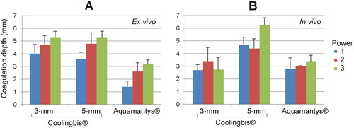
Table 4. Characteristics of the coagulation zones created ex vivo with the Coolingbis® devices (models 3 and 5 mm) and Aquamantys® in spot application mode (n = 5 applications per level power).
3.2. In vivo results
shows the characteristics of the coagulations zones created with the 3 and 5 mm Coolingbis® and the Aquamantys® using spot application on in vivo liver. Electrode sticking did not occur in any case. Unlike the ex vivo model, in the case of Coolingbis®, for the same programmed power level, the real power applied was lower with the 5-mm electrode. As the power level increased, coagulations with the 3-mm electrode showed slightly more bubbles and popping than with the 5-mm electrode. Coagulation depths showed less reproducible behavior than the ex vivo model. In the 3-mm electrode, the coagulation depths were similar for the three power levels, ranging from 2.7 to 3.4 mm. In the 5-mm electrode, the coagulation zones at low power level (1 and 2) were similar (4.4 − 4.7 mm) and slightly smaller than at power level 3 (6.3 mm). With Aquamantys®, coagulations produced less smoke than the Coolingbis® and coagulation depths were ∼3 mm, regardless of the applied power (20 − 30 W). Popping occurred with Aquamantys® and 3-mm Coolingbis®, but not with the 5-mm Coolingbis®. shows the coagulation depths created on in vivo liver using spot application with the Coolingbis® and the Aquamantys® devices.
Table 5. Characteristics of the coagulation zones created in vivo with the Coolingbis® devices (models 3 and 5 mm) and Aquamantys® in spot application mode (n = 5 applications per level power).
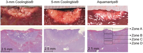
In the histopathological analysis, all the samples had coagulation areas with preserved lobular limits and architecture, with different levels of parenchyma distortion. We identified four concentric zones (see ). Zone A: Central zone with complete architecture disruption, presence of large holes surrounded by compacted necrotic tissue, which comprised cellular debris of hepatocytes and endothelial cells. Zone B: Coagulation necrosis zone where the hepatic trabeculae were distorted with partial sinusoidal collapse. The hepatocytes showed different intensity of pyknosis and marked hypereosinophilia. The sinusoids were well defined, empty or with scattered erythrocytes debris. The lobular wall connective tissue appeared necrotic, disconnected and hyperbasophilic, and blood vessel walls and portal duct were necrotic. Zone C: Vasodilatation zone in which the shape of the hepatic trabeculae was preserved, although some hepatocytes were swollen or necrotic. The sinusoids were distended without erythrocytes. Zone D: Congestive zone in which the hepatocytes were well preserved with markedly dilated sinusoids, full of erythrocytes and with congestion of the lobular walls and portal spaces. The lobule architecture and the hepatocyte morphology were intact in the outer zone. We found the four zones in the samples coagulated with the 3-mm Coolingbis® and Aquamantys® devices, but the zone A (presence of holes) was not present in the samples coagulated with the 5-mm Coolingbis®. As shown in , we found a good correlation between coagulation sizes measured from macroscopic (including a whitish zone) and microscopic samples (including zones A, B and C).
Figure 7. Histological findings from the in vivo coagulation zones created with the 3-mm Coolingbis® (1(A–D)), 5-mm Coolingbis® (2(A–D)) and Aquamantys® (3)A–D)) devices in spot mode.
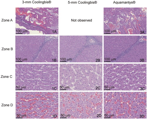
Figure 8. Comparison between macroscopic (top) and microscopic (bottom) samples from the in vivo coagulation zones created with the 3-mm Coolingbis®, 5-mm Coolingbis® and Aquamantys® devices in spot mode.
3.3. Relationship between applied power and coagulation depth
shows the linear regression equations between applied power and coagulation depth with spot application mode for the ex vivo and in vivo cases and for each device considered. The applied power explains the coagulation depth to some extent, with values of R2 between 0.35 and 0.73, except for the 3-mm Coolingbis® in vivo (whose analysis also presents very low statistical significance, p = 0.13). The effect of the applied power on coagulation depth is greater in the ex vivo case, as can be seen by the different slopes of the regression lines. The constant of the line depends on the device considered, with higher values for the 5-mm Coolingbis®.
Table 6. Linear regression equations between coagulation depth (D) and applied power (P) with the 3 and 5 mm Coolingbis® and Aquamantys® in spot application mode.
3.4. In-silico modeling
shows the RF power density in the tissue and saline layer for the Aquamantys®. Both side and top views illustrate very well the tendency to focus RF power almost exclusively in the space between the electrodes, while the side view shows how much RF power is dissipated in the salt layer between the electrodes. The percentage of power targeted on the tissue ranged from 51% (for 0.5 mm saline layer) to only 18% (for the 3 mm saline layer). The computer results also showed an increase up to 67% of the power targeted on the tissue when the electrodes were inserted deeper in the tissue (up to 2.75 mm).
4. Discussion
4.1. Main findings
This study aimed to characterize the coagulation zones created by two RF-based hemostatic devices based on different electrode designs (internally vs. externally irrigated) and mode of operation (monopolar vs. bipolar). In the context of surgical oncology, coagulation depth is critical, since it has to do simultaneously with intraoperative blood loss (which is clinically related to the risk of surgical morbidity and mortality) and even more importantly with local recurrence [Citation5,Citation6,Citation9]. The key findings of this study are as follows:
Both external (irrigation) and internal cooling effectively prevent tissue sticking, not only during the ‘painting mode’ (in which RF power is dispersed over a larger area to avoid overheating), but during spot applications, which are more prone to overheating and sticking.
Under ex vivo conditions and using the ‘painting’ application mode, coagulation depth increased with the applied power, from 2.8 to 5.6 mm with the 3-mm Coolingbis® device, from 1.6 to 6.0 mm with the 5-mm Coolingbis® device, and from 0.6 to 3.2 mm with the Aquamantys® device.
Coagulation depth in the ex vivo model showed less dispersion than in the in vivo model and also a higher dependence on the applied power.
Under in vivo conditions and using spot applications, the 3-mm Coolingbis® created coagulation zones of similar depth to the Aquamantys® (2.7 − 3.4 mm and ∼3 mm, respectively), while the 5-mm Coolingbis® created deeper coagulations (4.5 − 6 mm) with much less incidence of popping.
The presence of saline around the Aquamantys® electrodes shows that a significant percentage of RF power (50 − 80%) is dissipated in heating the saline itself. The hot saline then contributes to the coagulation of the tissue by thermal conduction, so that the coagulations are generally very shallow. This accounts for the differences in the ratio between coagulation depth and applied power for each device: 0.06 − 0.18 mm/W with 3-mm Coolingbis®, 0.04 − 0.07 mm/W with 5-mm Coolingbis®, and 0.02 − 0.04 mm/W with Aquamantys®.
There is no evidence that Coolingbis® and Aquamantys® create different coagulations from a histological point of view. The absence of holes (zone A) in the 5-mm Coolingbis® is possibly due to the less intense heating in the contact zone and could be related to the absence of popping.
4.2. Overheating and coagulation depth
Both external and internal irrigation of RF electrodes prevent the electrode from sticking to tissue. The tissue adhering to the electrode surface creates an insulating layer that prevents more power being delivered and therefore the effective use of the device. Although the two devices analyzed avoid sticking, they do so in very different ways. While the Aquamantys® uses external saline irrigation to preserve electrical conduction between the electrode and the tissue at all times, the Coolingbis® uses internal cooling to evacuate excess heat and prevent sticking. Our findings confirm that both approaches are able to minimize tissue sticking, which is commonly observed with conventional dry electrosurgical devices.
However, although neither of the two analyzed devices produce sticking, tissue overheating can occur at high power, associated with superficial bubbling, charring and creation of intra-tissue steam, which can cause an audible pop and even tissue disruption (cratering). In comparative terms, and for the ‘painting motion’ mode on ex vivo tissue, we found a tendency to charring with the 3-mm Coolingbis® (see ), even at a power as low as 30 W, possibly due to the high current density caused by the small contact surface. We also found some surface bubbling and smoke at high power (>75 W). The Aquamantys® was mainly characterized by a high incidence of surface bubbling even at low power (see ); the saline being what is really boiling. We also observed some smoke at power above 60 W. On the other hand, the 5-mm Coolingbis® showed signs of overheating only when very high power was applied (>140 W) (see ). Steam pops only occurred at very high power levels with all three devices. The behavior of all three devices was the same in spot applications, except for the fact that less power was required to produce signs of overheating (see ). This is reasonable, since the movement of the device over the tissue allows the power to be truly distributed over a larger volume of tissue, reducing the risk of overheating.
The overheating tendency of the 3-mm Coolingbis® is possibly related to its higher heating efficiency (from 0.18 to 0.09 mm/W for power levels from 1 to 6) than the other two devices (0.02 − 0.07 mm/W). In fact, shows a trend toward saturation in the coagulation depth from level 7 upwards, at which surface bubbling appears. This suggests that small electrode sizes work more reliably at low power levels. The ex vivo results suggest that the 5-mm Coolingbis® allows a greater range of coagulation depths to be created (from 1.6 to 6.0 mm) with less overheating than the 3-mm Coolingbis®. In fact, at the lowest power level, the 3-mm Coolingbis® creates a deeper coagulation zone (2.8 ± 0.4 vs. 1.6 ± 0.9 mm) despite applying less power (15.4 ± 1.3 vs. 37.0 ± 3.3 W).
Our findings also confirm that although a bipolar device generally creates more superficial coagulations than a monopolar device (see ), the size of a monopolar electrode, as well as its programmed power, can be such that it achieves similar surface coagulations to the bipolar device (e.g., with the 5-mm Coolingbis® at power level 1). For monopolar electrodes, the smaller the size, the greater the current density in the tissue and therefore it is more likely to create overheating and excessive desiccation with subsequently higher impedance and an inability to deliver more RF power. Although larger monopolar electrodes (up to 8-mm diameter) could deliver even more power and create larger coagulations with little overheating [Citation14], the problem is that the larger the electrode, the more difficult it becomes to coagulate delicate structures that require small controlled-size coagulation. In the case of bipolar electrodes, there is also a higher current density on the tissue surface as the electrode diameter is smaller. However, the situation is more critical since the RF power is confined to the tissue between both electrodes, which means that very small bipolar electrodes would produce rapid overheating and excessively superficial coagulations. From a histological point of view, similar coagulative thermal necrosis was created both with internally and externally irrigated electrodes (). The absence of holes in the 5-mm Coolingbis® was possibly associated with the absence of steam pops (see ).
4.3. Comparison of ex vivo and in vivo results
The comparison between ex vivo and in vivo results is not straightforward. While it would seem reasonable that the coagulation sizes were smaller in vivo due to the heat sink effect (absent in the ex vivo model), we found larger coagulations, at least with the 5-mm Coolingbis® and the Aquamantys® (see ), possibly due to the difference of the initial tissue temperature (room temperature in the ex vivo and 37 °C in the in vivo model), which directly affects electrical conductivity and therefore Joule effect heating. In the context of RF tumor ablation, we already observed computer results predicting larger coagulation sizes for the in vivo case at 37 °C than the ex vivo at room temperature [Citation15]. In other words, the initial temperature of the tissue possibly has a much greater impact than the heat sink effect by blood perfusion.
During the spot coagulations created by the 3-mm Coolingbis® on the in vivo model, we found very high power values and a large dispersion in coagulation size (see ). We think that one of the reasons was the variability in the contact surface between electrode and tissue due to the removal of Glisson’s capsule, which was done by surgical scissors. This action did not create a tissue surface as smooth as in the ex vivo model and the irregular surface allowed the electrode to be inserted deeper in some cases than in others, while the mechanical injury caused by the scissors caused local bleeding that created small blood pools in the surroundings of the electrode. This suggests that when the RF-based hemostatic devices consist of very small diameter electrodes (such as the 3-mm Coolingbis® and the Aquamantys® 2.3 bipolar sealer), the coagulation size could be highly dependent on the pressure exerted by the surgeon, since it directly affects the electrode-tissue contact area. Finally, in the comparison between ex vivo and in vivo results with the monopolar device (Coolingbis®) it should be remembered that the total volume of tissue between the device and the dispersive electrode is different, which may have caused the differences.
4.4. Clinical implications
Our results suggest that hemostatic devices based on RF electrodes (both externally and internally irrigated) are capable of generating zones of coagulative necrosis suitable for managing bleeding in surgical transection planes in the liver. While bipolar devices (such as the Aquamantys®) avoid the use of a dispersive electrode, they tend to create more superficial coagulations [Citation16], which is an advantage in terms of avoiding thermal damage to adjacent structures and preserving the parenchyma but can be a disadvantage in oncological surgery if it is intended to be used as a superficial ablative device to minimize local recurrence in the case of resections with a positive margin. On the other hand, monopolar devices tend to deliver the RF power deeper, achieving deeper coagulation zones, which can be both an advantage and a disadvantage for the reasons already mentioned.
Our computer results suggested the presence of the superficial saline layer in the Aquamantys® acts as an electrical current shunt between both electrodes, reducing the percentage of RF power applied directly to the tissue. In fact, the saline between the electrodes begins to boil within a few seconds of applying power, as can be seen by the high incidence of bubbles (see and ). The hot saline makes larger coagulation on the surface, although it may involve the risk of the saline migrating to adjacent organs [Citation17], while in the Coolingbis®, the saline cools the electrode internally (closed circuit), so there should be no liquid around the electrode, implying that theoretically 100% of the RF power is targeted on the tissue (even though the excess heating is evacuated by the closed circuit of cooled saline). However, in surgical practice it is common for the electrode to be partially surrounded by a pool of blood, so that hemostatic devices based on internally cooled electrodes such as the Coolingbis® should be used in close combination with an aspirator to keep the interface between electrode and tissue as fluid-free as possible. The use of an aspirator with externally irrigated electrodes is nonsense in the case of small blood loss, since the presence of the saline layer is required for the proper functioning of the device. However, in profuse bleeding, the necessarily intense use of the sucker could jeopardize its efficiency because of the unwanted aspiration of saline as well as blood.
Although in the context of surgical oncology RF-based hemostatic devices can be used to coagulate the surface of the remnant organ to increase the tumor-free margin, i.e., to ablate cells potentially suspected of being a tumor, the performance of the RF-based hemostatic devices is quite different from the RF applicators intended for focal RF tumor ablation, which are positioned more or less in the center of the tumor, while the RF energy is then applied in order to achieve an ablation zone encompassing the entire tumor plus a safety margin. It is a great challenge in terms of energy, since it is intended to ensure that coagulation necrosis extends up to 1 − 1.5 cm from the electrode surface [Citation18,Citation19], for which the applied power levels (>100 W) and durations (several minutes) [Citation20] are usually high. In contrast, RF-based intraoperative hemostasis uses electrodes positioned over the area to be treated, while the power levels must always be the minimum required to obtain the desired effect (as in any electrosurgical procedure). The surgeon has a direct view of the target and can modulate the power to attain the intended effect. In our study, the power was therefore progressively increased until audible pops were heard, which suggested too high a power. Note that, unlike our study, audible pops are almost irrelevant in the context of focal RF tumor ablation, in which they are usually associated with impedance roll-off, which, in impedance-control mode, simply requires a power off time before reapplying a new RF pulse.
4.5. Limitations
The first limitation of this study is that it was conducted only on porcine liver. It is expected that human tissue will exhibit different thermal and electrical characteristics resulting in different coagulation sizes. Despite this, there is no physical reason to suspect that the comparative conclusions between the two devices analyzed are different in the case of other tissues. The second limitation is that in order to keep the factors under control during the comparative in vivo study, only spot applications were conducted. Although this maneuver is done during surgery to avoid a bleeding point (see ), it is common for the surgeon to move the device over the transection plane. This movement prevents overheating and therefore favors the delivery of more RF power, which suggests that deeper coagulations could be created by applying more power for a longer time, as long as it is accompanied by a sufficiently rapid movement of the device to avoid overheating (particularly steam popping). In fact, power levels much higher than those used in our in vivo study are used in surgical practice with the Coolingbis®, so that coagulation deeper zones can be expected if the device is used intensively on the same area. For instance, coagulation depths up to 6 and 9 mm have been reported using internally cooled electrodes at ∼90 W during liver resection in a pig model [Citation21,Citation22]. The third limitation is that we chose the clinical power application modes and levels for each device (constant voltage for Coolingbis® and constant power for Aquamantys®), which prevented comparison at the same power levels (see ). The monopolar mode can be expected to require higher power, so that a comparison in terms of equal power would not ensure a comparison in optimal conditions of both devices, in addition to obtaining less clinically transferable conclusions. And finally, we only focused on RF-based hemostatic devices, which consist of electrodes that are in contact with the surface of the tissue to be coagulated, as there also exist other RF-based hemostatic devices (e.g., the LigaSure® sealer) in which the electrodes are embedded in clamp-type systems.
5. Conclusions
Both external (irrigation) and internal cooling of RF electrode-based hemostatic devices effectively prevent tissue sticking. The coagulation zones created in both cases are histologically similar. Saline-linked bipolar electrodes generally tend to create shallower coagulation zones than those made by an internally cooled monopolar electrode. The size of the coagulation zone is determined by the electrode size: a 3-mm monopolar electrode creates coagulation zones of similar depth to saline-linked bipolar electrodes (around 3 mm), while a 5-mm monopolar electrode creates deeper coagulation zones (4.5 − 6 mm) and produces considerably less steam popping.
Disclosure statement
Dr. Fernando Burdio is co-inventor of the US patent US 8303584 on which the Coolingbis device is based. The other authors have no relevant financial or non-financial interests to disclose.
Data availability statement
The data underlying this article will be shared on reasonable request to the corresponding author.
Additional information
Funding
References
- Ceppa EP, McCurdy RM, Becerra DC, et al. Does pancreatic stump closure method influence distal pancreatectomy outcomes? J Gastrointest Surg. 2015;19(8):1449–1456.
- Grasso G, Giambartino F, Iacopino DG. Hemostasis in brain tumor surgery using the aquamantys system. Med Sci Monit. 2014;20:538–543.
- Guild GN, 3rd, Runner RP, Castilleja GM, et al. Efficacy of hybrid plasma scalpel in reducing blood loss and transfusions in direct anterior total hip arthroplasty. J Arthroplasty. 2017;32(2):458–462.
- Kaibori M, Matsui K, Ishizaki M, et al. A prospective randomized controlled trial of hemostasis with a bipolar sealer during hepatic transection for liver resection. Surgery. 2013;154(5):1046–1052.
- Villamonte M, Burdío F, Pueyo E, et al. The impact of additional margin coagulation with radiofrequency in liver resections with subcentimetric margin: can we improve the oncological results? A propensity score matching study. Eur J Surg Oncol. 2022;48(1):82–88.
- Quesada R, Moreno A, Poves I, et al. The impact of radiofrequency-assisted transection on local hepatic recurrence after resection of colorectal liver metastases. Surg Oncol. 2017;26(3):229–235.
- Quesada R, Poves I, Iglesias M, et al. Laparoscopic partial splenectomy for giant cyst using a radiofrequency-assisted device: a case report. Surg Case Rep. 2016;2(1):82.
- National Library of Medicine (U.S.). Radiofrequency-assisted Transection of the Pancreas vs Stapler (TRANSPAIRE). 2020. Identifier NCT04402346. Available from: https://clinicaltrials.gov/ct2/show/NCT04402346
- Sui MH, Wang HG, Chen MY, et al. Assessment of the effect of the aquamantys® system on local recurrence after hepatectomy for hepatocellular carcinoma through propensity score matching. Clin Transl Oncol. 2019;21(12):1634–1643.
- Romano F, Garancini M, Uggeri F, et al. The aim of technology during liver resection — A strategy to minimize blood loss during liver surgery. In: Abdeldayem H, editor. Hepatic surgery. London: IntechOpen Ltd; 2013. p. 167–205.
- Currò G, Lazzara S, Barbera A, et al. The aquamantys® system as alternative for parenchymal division and hemostasis in liver resection for hepatocellular carcinoma: a preliminary study. Eur Rev Med Pharmacol Sci. 2014;18(2):2–5.
- Topp SA, McClurken M, Lipson D, et al. Saline-linked surface radiofrequency ablation: factors affecting steam popping and depth of injury in the pig liver. Ann Surg. 2004;239(4):518–527.
- Arenas J, Perez JJ, Trujillo M, et al. Computer modeling and ex vivo experiments with a (saline-linked) irrigated electrode for RF-assisted heating. Biomed Eng Online. 2014;13:164.
- Burdío F, Grande L, Berjano E, et al. A new single-instrument technique for parenchyma division and hemostasis in liver resection: a clinical feasibility study. Am J Surg. 2010;200(6):e75-80–e80.
- Trujillo M, Bon J, José Rivera M, et al. Computer modelling of an impedance-controlled pulsing protocol for RF tumour ablation with a cooled electrode. Int J Hyperthermia. 2016;32(8):931–939.
- S Hammond J, Muirhead W, Zaitoun AM, et al. Comparison of liver parenchymal ablation and tissue necrosis in a cadaveric bovine model using the harmonic scalpel, the LigaSure, the cavitron ultrasonic surgical aspirator and the aquamantys devices. HPB (Oxford). 2012;14(12):828–832.
- Gillams AR, Lees WR. CT mapping of the distribution of saline during radiofrequency ablation with perfusion electrodes. Cardiovasc Intervent Radiol. 2005;28(4):476–480.
- Zhang B, Moser MA, Zhang EM, et al. A review of radiofrequency ablation: large target tissue necrosis and mathematical modelling. Phys Med. 2016;32(8):961–971.
- Zhang B, Moser MAJ, Zhang EM, et al. A new approach to feedback control of radiofrequency ablation systems for large coagulation zones. Int J Hyperthermia. 2017;33(4):367–377.
- Fang Z, Moser MAJ, Zhang EM, et al. A novel method to increase tumor ablation zones with RFA by injecting the cationic polymer solution to tissues: in vivo and computational studies. IEEE Trans Biomed Eng. 2020;67(6):1787–1796.
- Burdío F, Navarro A, Berjano E, et al. A radiofrequency-assisted device for bloodless rapid transection of the liver: a comparative study in a pig liver model. Eur J Surg Oncol. 2008;34(5):599–605.
- Navarro A, Burdio F, Berjano EJ, et al. Laparoscopic blood-saving liver resection using a new radiofrequency-assisted device: preliminary report of an in vivo study with pig liver. Surg Endosc. 2008;22(5):1384–1391.