
Abstract
The present paper gives a concise overview of a number of current issues in the literature on texture formation in alloys with cubic crystal structures, mainly steel and aluminium alloys. As crystallographic texture determines to a large extent the anisotropy of material properties, it is of paramount importance to understand and control the physical mechanisms by which the texture is formed in the subsequent stages of metals manufacturing processes. In the present overview three key solid-state transformation processes are considered: allotropic phase transformations, plastic deformation and recrystallisation. The intention is to highlight a number of key elements in the literature and some recent tendencies, which may provide some insight to scientists and engineers dealing with texture issues in daily practice.
Introduction
Nearly all metals employed for structural applications are of polycrystalline nature and consist of large assemblies of grains, each of them exhibiting a specific crystal orientation. More often than not the manufacturing process of the metal alloy induces certain preferred crystallographic orientations and therefore, most metals exhibit a crystallographic texture. The study of crystallographic texture is important for three distinct reasons: (i) a multitude of material properties, and most noticeably the anisotropy of these properties are dependent on the crystallographic texture (essentially, each property that is orientation dependent in a single crystal will be texture dependent in the polycrystalline assembly); (ii) the appearance of a crystallographic texture tells something about the physical mechanisms that are involved in the formation of the microstructure. Theories on solid-state transformation processes occurring during metals processing such as phase transformation, plastic deformation or recrystallisation are incomplete without fully understanding the crystallographic implications of such theories, which also may entail consequences for texture formation. (iii) Since the late 1980s, knowledge on the crystallographic aspects of the microstructure has given rise to the development of orientation contrast microscopy, based on EBSD technique (Electron Back Scatter Diffraction). Nowadays EBSD provides one of the most complete and detailed metallographic imaging techniques in the resolution range accessible to scanning electron microscopy. The application of EBSD has opened the era of large-scale crystallographic characterisation on a SEM platform, which before was only accessible by Transmission Electron Microscopy (TEM). The progress in this field, which is not the subject of this paper, could not have been achieved without the contribution from texture-related knowledge.
The subject of this paper is a review on the formation of texture in metal alloys for structural applications, with an emphasis on metals with FCC and BCC crystal structure, though it will be attempted as much as possible to give a generic description of the solid-state transformations that are instrumental in texture formation. The texture aspects of allotropic phase transformation, plastic deformation and recrystallisation will be addressed in this paper from a physical metallurgical viewpoint, i.e. with an emphasis on the specific mechanisms that give rise to the development of the product textures starting from a parent texture at the onset of the process.
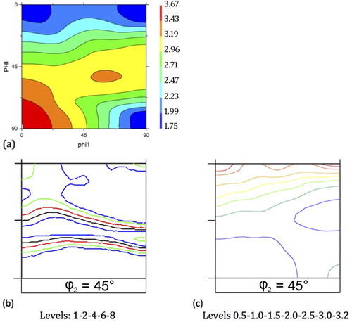
It is assumed that the reader is familiar with the basic principles of quantitative texture analysis. A number of essential monographs have been written on the experimental and theoretical tools that are currently available for texture characterisation.Citation1–3 Most of the textures in this paper will be shown as Orientation Distribution Functions (ODFs), which represent the frequency distribution of the continuum of orientations, conventionally represented in Euler Space. The ODF intensities will be expressed in ‘multiple of random density’ (mrd) units. represents the characteristic rolling texture components for FCC and BCC alloys. Because of orthorhombic sample and cubic crystal symmetry for FCC and BCC metals, only a sub volume of Euler space (with 0 ≤ ϕ1, Φ, ϕ2 ≤ 90°) is required to represent the entire texture. For convenience the FCC rolling textures are conventionally represented in the ϕ2 = 45°, ϕ2 = 65° and ϕ2 = 90° sections (), whereas for BCC rolling textures the ϕ2 = 45° section suffices (). lists a number of characteristic fibre textures, which are commonly designated with Greek symbols. Fibres represent a certain group of orientations with one degree of freedom in Euler space, e.g. the BCC γ-fibre groups all orientations for which <111>//ND. It should be noted that the identical symbols may define different fibres in FCC and BCC materials, cf. .
1 a Various fibre textures that are of relevance for rolling and annealing textures in FCC and BCC alloys; b ϕ2 = 45, 65 and 90° sections and c ϕ2 = 45° section, representing the characteristic components and fibres of the FCC and BCC rolling and annealing textures, respectively
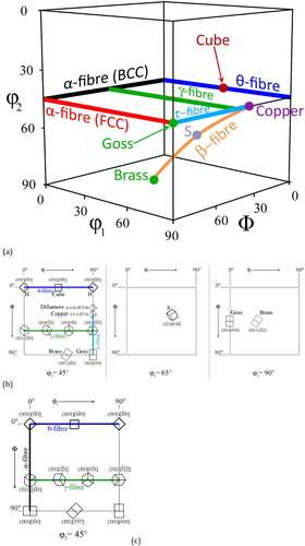
Table 1 Important texture components and fibres in FCC and BCC metals
Phase transformation textures
Most metal alloys exhibit various thermodynamically stable phases depending on the temperature and the precise chemical composition, at a given constant pressure. In a phase transformation the crystal structure of the alloy changes from an initial to a final structure, which implies an orientation relation from the parent to the product phase. The archetypical example is the FCC to BCC phase transformation in low-carbon steels. Depending on the characteristic carbon diffusion length at the transformation temperature, the product phase may appear under different morphologies: (i) ferrite or pearlite (long-range carbon diffusion), (ii) bainite (short range carbon diffusion) and martensite (no carbon diffusion). Although the microstructure, and the ensuing mechanical properties of these phases are largely different, from a crystallographic viewpoint the differences are less drastic. shows three ODFs, corresponding to a polygonal ferrite, an acicular ferrite and a martensite structure on a steel of the same composition.Citation5 Irrespective of the precise morphological appearance of the product phase, there seems to be little variation in the crystallographic orientation correspondence between parent and product phases.
2 ϕ2 = 45° sections of the ODFs of controlled rolled steel with a polygonal ferrite, b acicular ferrite and c martensite microstructureCitation5
The best known orientation relations that have been observed are the Kurdjumow–Sachs (K–S) and the Nishiyama–Wasserman (N–W) relations,Citation6 which are identified by the following correspondences {111}γ//{110}α <112>γ//<111>α and {111}γ//{110}α <110>γ//<111>α, for K–S and N–W respectively. These crystallographic rules identify the coinciding planes and directions of parent and product phases. In general the planar correspondence is better obeyed by the experimental data than the directional correspondence with observed deviations of ∼1° and 2–3°, for planar and directional coincidence, respectively.Citation7
The crystallography of the Phenomenological Theory of Martensite Transformation (PTMT)Citation8 assumes three contributions to the displacement associated with the austenite to martensite transformation: (i) the lattice transforming Bain strain, (ii) a lattice invariant shear strain in the martensite phase to obtain an zero-distortion plane and (iii) a lattice rotation that makes the zero-distortion plane coincide with the initial position so as to obtain an invariant plane. The exact orientation relation between parent and product phases can be calculated by specifying (i) the lattice correspondence that links the lattice vectors of parent and product phases (e.g. the Bain strain <001>45°), (ii) the active slip systems of the lattice invariant shear (e.g. {110}<111> slip for lath martensite and {112}<111> twinning for plate martensite) and (iii) the lattice parameters of parent and product phases (though in some cases, more than one solution is possible on the basis of PTMT).Citation9 In general the PTMT predicted orientation relations are very close to the observed K–S or N–W correspondences for lath and plate martensite, respectively.Citation10 The intriguing feature is that the same orientation relations are also observed in non-displacive, i.e. diffusive, transformations whereby no martensite is involved.Citation11,Citation12 It seems reasonable to assume that the interface energy in the nucleation stage plays an important role in the crystallography of the austenite-to-ferrite transformation, whereby the orientation relations K–S or N–W provide a coherent interface in the early nucleation stage, reducing the activation energy for nucleation (cf. infra).
Already a number of extensive reviews have been published on the transformation textures that appear in low-carbon steel after hot rolling.Citation5,Citation13 The most decisive hot rolling parameter for the texture formation in hot rolling product is the nature of the hot-rolled structure at the point of transformation. If the parent austenite structure is recrystallised the product texture is very weak and characterised by three components: {001}<110>, {110}<001> and {110}<110>, cf. .Citation14 If the parent austenite structure has accumulated strain without recrystallisation (i.e. a number of rolling passes were applied below the austenite non-recrystallisation temperature Tnr) then an entirely different transformation texture appears, which is shown in .Citation14 This texture has increased intensity and it is dominated by the {112}<110> and by the {554}<225> components, which are connected by the BCC β-fibre (not to be confused with the FCC β-fibre). The origin of the hot rolling transformation texture is relatively well understood. The features of the textures of can be modelled by applying the K–S transformation rules on a parent texture that is dominated by the cube component,Citation15 which is the natural dominant component of most FCC recrystallisation textures after rolling.Citation16 In a similar manner the transformation texture of can be explained by applying the K–S correspondence on an FCC rolling texture, which is characterised by the FCC β-fibre texture.Citation17
3 ϕ2 = 45° sections of transformation textures of IF steel, hot rolled with various finishing temperatures TfCitation14
An important question with respect to transformation textures is the role of variant selection. Depending on the precise crystallographic orientation relation between parent and product phase, one parent orientation will give rise to N product variants (with N = 12 for N–W and N = 24 for K–S orientation relations), i.e. physically distinct product orientations that arise from applying the crystal symmetry operators to the specific orientation relation under consideration. In experimentally observed transformation textures, only in rare cases all N variants are observed. The phenomenon whereby only a limited number n of the N potential variants appears in the product texture is called variant selection. Various hypotheses have been postulated in the literature about the origin of variant selection. A distinction must be made between variant selection observed in diffusive and displacive transformations. In the latter type the PTMTCitation8 offers an appropriate theoretical framework for variant selection because the theory specifies precisely how the volume and shape change is accommodated by the transformation, i.e. the transformation displacement field Lγ– α is calculated. When the transformation occurs under the action of an external load σ, the work exerted by this load can be calculated as W = σ : Lγ– α. This mechanical work needs to be added to the thermodynamic driving force, i.e. it represents the micromechanical contribution to the change in Gibbs free energy (driving force) associated with the transformation. For each crystallographic variant i of the transformed crystal a different value Wi of the work is obtained, because the displacement gradient Lγ– α is differently oriented with respect to the external load. Hence the driving force for transformation is orientation dependent. By assuming that a unit tensile load is applied along the TD direction, the orientation dependence of the driving force could be calculated.Citation18 These simulation results were confirmed by in-situ experimentalCitation19 data, whereby it was observed that crystal orientations with the highest micro-mechanical driving force are the ones that transform first. A nearly linear correspondence exists between the micro-mechanical component of the driving force for specific orientations and the sequence of appearance of these orientation in the transformation texture, cf. .
4 Transformation potential versus the experimental transformation rate of 11 randomly chosen austenite orientations in a TRIP steel under tensile loadingCitation19
The same principle of the micro-mechanical driving force contribution remains valid also in absence of an externally applied load, by considering the accommodating crystallographically anisotropic environment surrounding the nucleating martensite laths or plates. There is ample crystallographic evidence that new martensite nuclei form in a self-accommodating manner, so as to reduce the transformation work, which is required by the displacement field.Citation20,Citation21 Martensite laths or plates are formed in packages, which are either confined to a parent austenite grain, or which may give rise to a new subsequent nucleation event in a neighbouring crystal. The micromechanically dissipated work will critically depend on the local mechanism of accommodation and one nucleation event will affect the next. Malet et al.Citation22 were able to model the precise crystallographic martensite variants appearing in the austenite parent grain of an Fe-30%Ni alloy.
Another mechanism of variant selection is prevalent in non-displacive transformations. There is solid experimental evidence that new ferrite nuclei appear in the parent phase austenite at specific grain-boundaries (GB) that allow for a double orientation relation of the type K–S or N–W at either side of the GB, cf. .Citation11,Citation23 The double orientation relation reduces the α/γ interface energy and therefore reduces the activation energy for nucleation, which is of crucial importance during the early stages of nucleation. It can be calculated that in a random set of 4000 austenite orientations approximately 1% of the misorientations will allow for a double K–S orientation relation within a tolerance of 5°. The mechanism of GB nucleation with double K–S orientation relation allows explaining three distinct features of the ferrite transformation microstructure: (i) texture memory after forward and reverse α−γ−α transformation and concurrent increase in grain size associated with texture memory,Citation24,Citation25 (ii) manifestation of variant selection, even in pure reconstructive transformations of a recrystallised austenite structure and (iii) significant reduction of in-situ experimentally measured activation energy of transformation as compared to the predicted activation energy on the basis of Classical Nucleation Theory.Citation26
5 Schematic representation of the process of texture memory. a two austenite grains with different KS relationships nucleating along a ferrite grain boundary, b the structure after complete transformation to austenite, c nucleation of a ferrite grain on cooling with YKS relationship to both neighbouring austenite grains, d final structure after displacive growth of the ferrite—the original grain orientation α2 is restoredCitation24
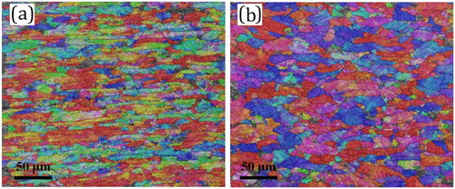
In a recent series of papers, the specific orientation relation between parent and product orientations was employed to reconstruct the high-temperature austenite structure from an EBSD scan of the room temperature martensite structure.Citation27–30 Various groups have developed different algorithms, which vary in the way in which the specific orientation relation between parent and product phase is assessed and in the tolerance that is allowed on these orientation relations. Most methods still require operator interference to some extent, although new operator-independent methods are being developed.Citation31 As can be observed from the microstructure of ,Citation32 high resolution reconstructed austenite phase maps can be generated, which reveal crucial information on the type of parent phase microstructure on the point of transformation. Such maps will allow for more accurate control of the hot rolling process, and hence a better control of the transformation texture. E.g. in the map of and b,Citation32 the difference can be observed between a recrystallised and deformed austenite parent structure, which largely determines the type of transformation texture that will be obtained.
6 Reconstructed austenite parent structure from EBSD scan of a product phase, finished rolled a below and b above the austenite Tnr temperatureCitation32
Deformation textures
The orientation of metallic crystallites after plastic deformation depends on different parameters such as chemical composition, working temperature, initial texture and history of deformation. However, the dominant factors—which highly influence the development of the deformation texture—are the crystal structure of the metal and the nature of plastic deformation, i.e. the deformation mode and its magnitude.
In most metals plastic deformation at room temperature is accommodated by slip or twining in systems composed of specific crystal planes and directions. Twinning provokes abrupt change of crystallographic orientation across the twinning plane, while the slip process induces crystal lattice rotation, which will bring the crystal in a position corresponding to the strain forced upon it, e.g. in tension the active slip direction moves in the direction parallel to the tensile axisCitation32,Citation33 (cf. ). In polycrystalline metals, this re-orientation of grains develops the deformation texture. As rolling is the most common metal forming process, a brief review will be given first of the conventional rolling textures.
7 Schematic representation of lattice rotation as a consequence of slip activity in a single crystal with hypothetical primitive cubic structure: a initial situation, b crystal after unit shear and c lattice rotation imposed by boundary condition of fixed tensile axisCitation33
Rolling texture in FCC metals
In FCC metals, the slip and twinning systems are {111} <110> and {111} <112>, respectively. The rolling texture in the metals with FCC structure depends on the stacking fault energy (SFE), the deformation temperature and the rolling reduction.Citation33,Citation34 SFE plays an important role in determining the dominant mechanisms of plastic deformation. In metals with high SFE (e.g. aluminium and copper), slip is the dominant deformation mode and the rolling texture is composed of copper, brass and S texture components with nearly equal intensities.Citation33–37 The miller indices and the Euler angles of these components and the other common texture components in rolled FCC metals are given in . This type of texture is known as the pure metal texture or copper-type texture (cf. ).
8 a Pure metal type texture of 95% cold rolled copper alloy, with strong Cu component b and Brass-type texture of brass alloy (70:30) with maximum on Brass componentCitation38
On the other hand, metals with low SFE (as a rule of thumb metals with higher alloy content such as e.g. 70:30 brass or austenitic stainless steel) exhibit a tendency for mechanical twinning during plastic deformation, in addition to dislocation glide. The rolling texture in these metals is known as alloy-type texture (also known as a brass-type or silver-type texture) and is composed of a strong brass component and a minor Goss orientation,Citation37 cf. .
In alloy systems, the SFE depends on the amount of solute elements and its variation will be observed in the corresponding rolling texture. As an example, the addition of cobalt to pure nickel drastically reduces its high SFE (∼130 mJ m−2).Citation39 The rolling texture of Ni–Co alloys containing up to 30%Co are rather similar to that of pure Ni (cf. ), whereas the rolling texture of the alloy with 60%Co is of alloy-type (cf. ). The texture of the alloy with 40 wt-% Co shows features which are common to both types of textures, i.e. a texture transition from pure metal texture to alloy-type texture (cf. ). This texture transition has been attributed to the additional effect of the mechanical twinning caused by the drastic decrease of the SFE of Ni by Co-addition.Citation40 Similar results have been observed in Cu-Zn alloy systems with different Zn contents.Citation38
9 { 111} Pole figures representing the rolling textures of low to high SFE FCC metals and alloys: a pure Ni, b Ni-10% Co, c Ni 20% Co, d Ni 30% Co, e Ni 40% Co, f Ni 60% CoCitation40
Rolling temperature is another factor, which influences the type of texture the produced in rolled FCC metals. For example, 304L stainless steel rolled at 200°C develops an alloy-type texture, whereas the same alloy develops a pure metal texture after rolling at 600°C.Citation41 The direction of this texture transition is consistent, i.e. the alloy-type texture is changed to the pure metal texture by increasing the rolling temperature and vice versa as the activation energy for dislocation glide is more temperature dependent than the SFE.
The effect of rolling reduction on the developed texture seems to be of less importance in comparison with SFE and rolling temperature. However, it has been observed that by increasing the rolling reduction (i.e. strain) not only a sharper texture will develop, but also the location of the peaks in the pole figures changes, which requires more cautions especially when the texture is analysed based on individual orientations.Citation3
Rolling texture in BCC metals
Due to the industrial importance, steel alloys (especially the low- and extra-low-carbon steels) have been the subject of most works on the deformation textures of BCC metals. The rolling texture of all BCC metals and alloys (e.g. iron, tantalum, β-titanium, vanadium and molybdenum) is almost the same but different from the FCC rolling textures. This difference arises from the presence of different active slip systems in these crystal structures. In FCC metals, the dominant slip system is {111} <110> (at room temperature), whereas in BCC metals, the slip direction is always <111>, but the slip planes can be {110}, {112} and, perhaps {123}. Furthermore, under various conditions, BCC metals also slip on other planes, which is described by the term ‘pencil glide’.Citation42
As opposed to FCC metals, the rolling texture of the BCC metals is not considerably affected by solute additions. The typical texture of rolled BCC metals is composed of a partial α-fibre (running from {001}<110> to {111}<110>) and a γ-fibre (running from {111}<110> to {111}<112>), also known as RD-fibre and ND-fibre, respectively.Citation41Citation42–Citation43 A number of reviews can be consulted for describing rolling texture in steels.Citation44Citation45–Citation46 In low-carbon steels, the two fibres are equally developed after convention rolling reduction of 75%, cf. . By raising the rolling reduction, the texture becomes continuously stronger, cf. and c. Although the major characteristics of the BCC rolling texture are almost unchanged during deformation, by increasing the reduction to 83 and 90% the {112}<110> of the α-fibre becomes more prominent. By accumulative roll bondingCitation47 even higher reductions can be applied and it can be observed that with true strains exceeding 3.0, corresponding to rolling reductions larger than 95%, the γ-fibre depletes at the expense of the α-fibre intensity, cf. . At the highest reduction of 99.9% (true strain 6.9) the absolute intensity maximum of 30 mrd is positioned on the rotated cube component {001}<110>. While the typical texture components of rolled BCC steels are almost independent of processing variables, the presence of solute elements or precipitates, it is well documented that the cold-rolling texture is affected by the hot-rolled texture prior to cold rolling.Citation41,Citation48
10 Cold-rolling textures of IF steels after conventional rolling with 75, 83 and 90% reductions and after accumulated roll bonding with 98.4 (ε = 4.2), 99.6 (ε = 5.4) and 99.9 (ε = 6.9) reductions. Levels: 1-2-4-6-8-11-14-18-22-26-30
Deformation structure
Dislocation induced structures in pure aluminium, copper and some of their alloys have been extensively studied in the last decades. On a meso-scopic scale grains are subdivided during deformation in deformation bands and on a more microscopic scale in cell blocks (CBs) and cells. Parallelogram-shaped CBs, which are delineated by planar dislocation walls, contain cells surrounded by incidental dislocation boundaries, cf. .Citation49,Citation50 Dense Dislocation Walls (DDWs) are of a thin planar nature, whereas Microbands (MBs) are thicker and can be distinguished as double boundaries in TEM. Hansen et al.Citation51–53 experimentally observed the deformation phenomena with TEM in the tensile deformed pure aluminium. They illustrated three types of boundaries: type 1 in which the DDWs are aligned with the trace of the slip planes {111}, type 2 with no extended boundaries and only with an equiaxed cell structure and type 3 in which DDWs are not showing any obvious alignment with {111} planes.Citation52
11 Schematic drawing of deformation microstructures in FCC metals and alloys representing cell structure, MB and DDWsCitation50
There is a lot of controversy on the crystallographic nature of these phenomena. According to Hansen et al. Citation54 the DDWs are formed parallel to the most stressed {111} plane and later they align with the maximum shear plane. However, Winther et al.Citation55–58 observed DDWs aligned with other crystallographic planes. In the earlier work of Huang and HansenCitation59 the average deviation of the DDW trace with the nearest {111} planes was found to be 5° and in the later work of Winter et al.Citation53,Citation54 this deviation was found to be more than 10°. Both studies were carried out on tensile strained high purity (99.99%) Al samples. Based on these studies, a clear relationship between grain orientation and the dislocation structure was established. Also the crystallographic orientation of the grain was found to be the key material parameter in controlling structural evolution. This evolution cannot be random but it involves rotations directly related to the preferred crystallographic orientation of grains.
During plastic deformation individual grains in polycrystalline materials fragment into regions of different orientation. This can be the result either of an intrinsic instability of grains or of boundary conditions imposed by adjacent grains.Citation39 Grain subdivision is of great importance for metal forming processes because it significantly affects the evolution of microstructure and texture, mechanical properties and plastic anisotropy of the material. Grain subdivision during severe plastic deformation (SPD) is also of technological importance as it is intensely investigated as a method of bulk metal grain refinement in the nano-size scale.Citation60 With regard to texture formation during SPD, it is observed both in IF steel and commercially pure aluminium that orientations tend to evolve to a stationary texture, which is rather weak (close to random), but results are dependent on the deformation temperature and the chemical composition of the alloy.Citation61,Citation62
Shear bands (SBs) are a particular instance of plastic heterogeneities, occurring at medium to high-level strains, which is the result of plastic instability. SBs are microscopic or macroscopic planar regions of severe shear, which in rolled metals are aligned parallel to the transverse direction and inclined to the rolling plane, most frequently with an angle of 35°.Citation33 Macroscopic SBs are non-crystallographic features and may form through the entire thickness of the sheet crossing several grains, particular in low-stacking fault materials, at elevated strains rates or at low temperatures.Citation63 Microscopic SBs or in-grain SBs are most frequently observed in crystal orientations that require ample slip activity to accommodate the imposed plastic strain (i.e. the so called Taylor hard grains, cf. infra). In BCC materials in-grain SBs most readily occur in {111}<211> orientations.Citation64
Recrystallisation textures
Most alloys are not used in the full-hard condition, but are soft annealed after deformation. During this annealing treatment, thermally activated processes occur as soon as the temperature rises above approximately one third of the homologous melting temperature Tm/3 (expressed in K). These processes reduce the density of crystal defects and give rise to a structure that is closer to thermodynamic equilibrium. Textbook knowledgeCitation65 on recrystallisation makes a distinction between different types of thermally activated softening processes: recovery, recrystallisation and grain growth, which normally take place in subsequent stages, although overlap between stages may occur.
Substructural recovery can be considered as a precursor to recrystallisation. During recovery the system reduces its internal energy by short range dislocation interactions, whereby the dislocation density drastically drops by annihilation of dislocation dipoles and the remaining dislocations are stacked in low-energy configurations, often forming subgrain structures composed of low-angle grain boundaries. The subsequent recrystallisation stage involves a process of nucleation of strain free crystallite volumes, which afterwards consume the entire deformed microstructure by migration of high-angle grain boundaries. It needs to be borne in mind that the nucleation stage of recrystallisation is itself a process of subgrain boundary migration and therefore the classical nucleation theory, as e.g. applies to phase transformations, is not valid here.Citation66 As any other thermally activated process, the recovery and recrystallisation rates are determined by the balance between driving force and mobility. In this case the driving force is delivered by the dislocation density, induced by plastic deformation, whereas the mobility is largely determined by the activation energy for boundary migration (cf. infra). A recrystallisation texture may appear because of two possible causes: (i) specific orientations may be preferred during the nucleation stage for recrystallisation, i.e. oriented nucleation or (ii) they may be preferred for fast growth, i.e. selective growth. A number of comprehensive reviews on recrystallisation textures have already been published, with strong emphasis on the fierce scientific debate between adherents of orientated nucleation and selective growth theories.Citation16,Citation47,Citation67
Orientation dependent driving force
Crystal plasticity theory predicts that the plastically dissipated power depends on the crystal orientation g for a given strain mode L. The Taylor factor M(L, g) represents a dimensionless measure of the plastically dissipated power:Citation68
whereby τ0 is the critically resolved shear stress, dγi is the instantaneous slip increment on slip system i, s is the number of active slip systems, σ0 is the flow stress and εvM is the von Mises equivalent strain.
In a first approximation the Taylor factor can be considered as being proportional to the accumulated plastically stored energy and thus providing a measure of the orientation dependent driving force for recovery and recrystallisation.Citation46 One may reasonably assume that the orientations with the highest driving force for recrystallisation, i.e. the orientations with the highest Taylor factor (cf. ) are among the first and the most numerous to nucleate and therefore such orientations will dominate the nucleation texture. This mechanism is referred to as high stored energy nucleationCitation69 and is observed in cold rolled low-carbon steels, where it gives rise to the well-known γ-fibre recrystallisation texture, appearing after annealing of the cold rolled sheet cf. . This texture is very much wanted for some applications as it gives rise to favourable deep drawing properties.Citation58,Citation59
12 a Taylor factor map for plane-strain compression with {211}<111> and {110}<111> slip in BCC crystals. Typical recrystallisation textures after annealing of low-carbon steel b after conventional cold rolling to a reduction of 80% and c after warm rolling in the ferrite domain followed by static recrystallisation
In other instances, however, high stored energy nucleation is not observed, but contrarily low-stored energy orientations are selected for nucleation, corresponding to orientations with the lower Taylor factor (cf. ). E.g. when a low-carbon steel sheet is warm rolled in the ferrite phase and afterwards annealed, a recrystallisation texture appears that is dominated by the cube fibre <100>//ND, which are orientations of low-stored energy, cf .Citation70 Also in the case of asymmetric warm rolling, whereby the strain mode is characterised by a combination of plane-strain compression (PSC) and simple shear, the hypothesis of low-stored energy nucleation accurately describes the prominent components of the recrystallisation texture.Citation71
The reason for such apparent contradiction is as yet not well understood. One possible explanation involves the role of recovery, preceding the onset of nucleation. The stored energy of plastic strain that delivers the driving force for nucleation also represents the driving force for the recovery process. If recovery has already consumed a significant fraction of driving force (whether or not dynamically) then it may come to a point that the ensuing recovered structure in the low-stored energy grains has already transformed to an early nucleation structure,Citation72 which is ready to consume the deformed structure, whereas in the remaining high stored energy grains enough driving force remains for extensive generation of nuclei. In this respect it is interesting to observe that low-stored energy nucleation seems to be prevalent after high-temperature deformation,Citation73 whereas the opposite is true after low temperature deformation.Citation74 It is reasonable to assume that (dynamic) recovery of Taylor hard grains (i.e. the ones with high Taylor factor) is more favoured at high temperature because of kinetic effects and thus less driving force for recrystallisation remains for these grains.
One of the most peculiar instances of texture formation during recrystallisation is the formation of a very intense and exclusive cube component during annealing of cold rolled FCC materials with medium to high SFE under appropriate conditions of chemical composition, deformation temperature, rolling reduction and initial grain size. In a paper of 1986 the formation of the cube texture was quoted ‘as a great wonder of nature’.Citation75 During many years there was a fierce debate in the scientific literature about the origin of this component,Citation76 whereby different theories of oriented nucleation and oriented growth were proposed. It is now generally accepted that the nucleation of cube oriented grains is largely enhanced by the fact that cube grains are particularly prone to easy recovery because plane-strain compression activates four slips systems in ideal cube orientations with only two distinct Burgers vectors that are perpendicular to each other. As a consequence these dislocations have minimum elastic interactions and therefore they are less restricted in their movement and more readily susceptible to recovery.Citation77
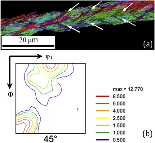
Already in early literature Hutchinson and UshiodaCitation78 have explained the nucleation of Goss oriented grains in shear textures observed in {111}<211> orientations in Fe-Si alloys with BCC crystal structure. Their theory was based on the Dillamore criterion of geometric softening by localised shear in high Taylor factor grains, such as {111}<211> orientations.Citation79 The bifurcation criterion, whether or not to occur localised shear, is based on the energetic balance of plastically dissipated power between homogeneous deformation in the entire volume of the deforming grain or increased localised shear in the sub-volume of a SB that is parallel to TD and inclined with an angle α with respect to RD. The same criterion was applied on {110}<110> oriented grains, which also exhibit a very high Taylor factor and therefore are prone to geometrical softening by shear banding.Citation80 In this case the model predicted the formation of cube orientation {001}<100> in such SBs, which were indeed observed experimentally, cf. .
13 a {110}<110> oriented deformed grain in cold rolled Fe-3%Si steel exhibiting in-grain SBs, indicated by white arrows; b ODF of the {110}<110> oriented grain together with the {001}<100> cube orientations of the SBsCitation80
It is also accepted that the deformation temperature plays an important role in the formation of localised SBs. BarnettCitation64,Citation81 pointed out that low-carbon steels, with a carbon content in the range of 0.02 to 0.05 exhibit a negative strain rate sensitivity m in the approximate temperature range of 150 to 250°C due to dynamic strain aging. As a result of such negative m values, low-carbon steels exhibit excessive shear banding after warm rolling in this temperature range, which gives rise to a strong Goss component {110}<001> after recrystallisation. In IF-steels, with the carbon solutes removed from the ferrite lattice by micro-additions of Ti and/or Nb, the behaviour is markedly different. Here the strain rate sensitivity is virtually temperature independent until ∼Tm/2 and hence the IF steels exhibit typical γ-fibre texture, even after ferrite rolling at temperatures of 650 to 700°C.Citation73
Mobility considerations
Both recovery and recrystallisation occur by thermally activated migration of dislocations, dislocation boundaries, low- and high-angle grain boundaries. Recovery processes transform the cellular deformation substructure, associated with high-stacking fault materials, to a subgrain structure, which is intricately instable and upon further thermal activation individual subgrains may grow abnormally, coalesce or bulge out, forming new strain free recrystallisation nuclei.
There has been a lot of debate on the effect of structural and chemical characteristics on the boundary characteristics. Conclusive evidence has been delivered for the reduced mobility of low-angle grain boundaries and the associated effect of orientation pinning. According to Vandermeer and Juul Jensen,Citation82 orientation pinning of low-angle grain boundaries contributes to the enhancement of the cube texture formation in FCC alloys. A lot of attention has been paid to the effect of crystal misorientation on the mobility of high-angle grain boundaries. It was claimed that the <110>30° and the <111>40° misorientations in BCC and FCC crystals, respectively, are associated with an increased mobility of the grain boundary.Citation16 However, such claims remain highly controversial because: (i) there are no specific structural arguments supporting the unique character of these orientation relations; (ii) the orientation relation in itself does not give a complete description of GB structure (because it ignores the inclination of the GB plane) and (iii) it is difficult in growth experiments to separate mobility effects from variations in driving force. An important contribution to the debate was made by Hutchinson et al.Citation83, who studied the random distribution of misorientations, represented by a set of axis-angle pairs <UVW>ω, whereby the axis is selected that is closest to <110> or <111> (instead of the more common minimum angle representation). They showed that such a misorientation distribution function exhibits a peak close to 30° for the <110> axes and close to 40° for the <111> axes, cf. . Nevertheless, it was equally shown by numerical simulations that for FCC aluminium, the consideration of the <111>40° increased mobility operator was an essential element in obtaining a reasonable agreement between modeled and experimental textures,Citation84 whereas Verbeken et al.Citation85 showed that even in the representation proposed by Hutchinson et al.Citation83 there is a statistically significant preference for <110>26.5° selective growth of random nuclei introduced in a BCC Fe-Si single crystal.
14 Frequency distribution of random misorientations; a represented with misorientation axes nearest to <110> and b with misorientation axes nearest to <111>. ‘all’ includes all misorientations, ‘10°’ misorientations within a tolerance of 10° from the axis and ‘5°’ within a tolerance of 5° from the axisCitation83
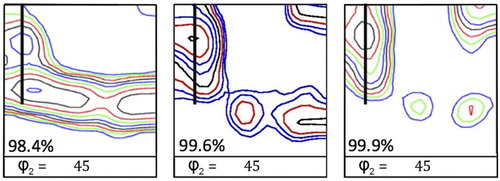
A very peculiar recrystallisation texture arises in low-carbon ferrite steel after heavy cold rolling (>95% reduction) and annealing. With increasing rolling reduction the well-known γ fibre recrystallisation texture is gradually substituted by one or more components of the {h11}<1/h,1,2> fibre (cf. ), which appears in the ϕ2 = 45° section on a line parallel to the α-fibre with 0 < Φ < 35°. The formation mechanism of this component is still largely unknown, although the presence of a strong α fibre with an intense maximum on the rotated cube component {001}<110> seems to be a necessary prerequisite for the development of the {h11}<1/h,1,2> fibre during recrystallisation. This condition may arise after large rolling reductions (cf. )Citation86 or after conventional rolling reductions, whereby the rolling direction is changed between each rolling pass (cross rolling).Citation87 Although it has been observed that the {311}<136> component exhibits a specific <110>26.5 orientation relation of potential fast growth with the dominant {211}<110> coλδ ρoλλing orientation,Citation85,Citation88 it is equally true that {h11}<1/h,1,2> fibre orientations have been observed in the fragmented substructure of {001}<110> orientations after cross rolling.Citation89 As the {h11}<1/h,1,2> fibre orientations are already present in the early nucleation texture, it is likely that oriented nucleation plays a role in the formation of {h11}<1/h,1,2> textures.
15 Recrystallisation textures obtained after annealing at 750°C for 180 s of ARB cold rolled IF steels samples to an accumulative reduction of 98.4 (ε = 4.2), 99.6 (ε = 5.4) and 99.9 (ε = 6.9), respectively. The black bold lines indicates the {h11}<1/h,1,2> fibre. Levels: 0.7-1.0-1.4-2.0-2.8-4.0-5.6-8.0-11-16
Concluding remarks
Materials science is different from condensed matter physics in the sense that materials science deals with engineered materials that exist and are employed in the real world beyond the well-posed boundary conditions of laboratory tests or theoretical models. The microstructure of metal alloys for structural applications is of key importance for obtaining the target mix of properties. Microstructures are intricately complex as they are allowed the many degrees of freedom provided by the wide variety of lattice defects, which are the basic building blocks of the microstructural phenomenon. The scientific way of dealing with complexity is by applying statistical methods, which are capable of revealing certain patterns in the diffuse reality of experimental data.
Texture study in materials science is in essence a quantitative statistical study of crystallographic phenomena that contribute to the shaping of microstructure. It filters out the relevant crystallographic orientations that appear in solid-state transformation processes, occurring during making and using of materials. Hence, detailed study of the textures, as made possible by evermore sophisticated experimental instruments and more powerful numerical tools, provides a major gateway to better understanding the complex mechanisms involved in phase transformations, plastic deformation and thermally activated recovery. The present paper has presented a minute review, by no means exhaustive, of acquired achievements over the past decades and current open issues in the texture literature.
Acknowledgment
The authors would like to acknowledge the Interuniversity Attraction Poles Program (IUAP) of the Federal Science Policy of Belgium and the partners of IUAP-VII-project P7/21 ‘Multiscale mechanics of interface dominated materials’.
References
- H. J. Bunge: ‘Texture analysis in materials science: mathematical methods’, 1993, 593, Göttingen, Cuvillier Verlag.
- V. Randle and O. Engler: ‘Introduction to texture analysis: macrotexture, microtexture and orientation mapping’, 2000, CRC Press, Boca Raton, FL. doi:10.1046/j.1365-2818.2001.00936.x.
- U. F. Kocks, C. N. Tomé and H.-R. Wenk: ‘Texture and anisotropy: preferred orientations in polycrystals and their effect on materials properties’, 2000, Cambridge, Cambridge University Press.
- J. J. Sidor and L. A. I. Kestens: ‘Analytical description of rolling textures in face-centred-cubic metals’, Scr. Mater., 2013, 68, 273–276. doi: 10.1016/j.scriptamat.2012.10.039
- R. Ray and J. Jonas: ‘Transformation textures in steels’, Int. Mater. Rev., 1990, 35, 1–36.
- Y. He, S. Godet, P. J. Jacques and J. J. Jonas: ‘Crystallographic relations between face- and body-centred cubic crystals formed under near-equilibrium conditions: observations from the Gibeon meteorite’, Acta Mater., 2006, 54, 1323–1334.
- G. Miyamoto, N. Takayama and T. Furuhara: ‘Accurate measurement of the orientation relationship of lath martensite and bainite by electron backscatter diffraction analysis’, Scr. Mater., 2009, 60, 1113–1116.
- H. K. D. H. Bhadeshia: ‘Worked examples in the geometry of crystals’, 2001, London, The Institute of Metals, doi:10.1524/zkri.1991.195.1-2.155.
- H. K. D. H. Bhadeshia, H. Abreu and S. Kundu: ‘Calculation of crystallographic texture due to displacive transformations’, Int. J. Mater. Res., 2008, 99, 342–346.
- L. Malet and S. Godet: ‘On the relation between orientation relationships predicted by the phenomenological theory and internal twins in plate martensite’, Scr. Mater., 2015, 102, 83–86.
- H. Landheer, S. E. Offerman, R. H. Petrov and L. A. I. Kestens: ‘The role of crystal misorientations during solid-state nucleation of ferrite in austenite’, Acta Mater., 2009, 57, 1486–1496.
- H.-R. Wenk, I. Huensche and L. Kestens: ‘In-situ observation of texture changes during phase transformations in ultra-low-carbon steel’, Metall. Mater. Trans. A, 2007, 38, 261–267.
- W. B. Hutchinson, L. Ryde and P. S. Bate: ‘Transformation textures in steels’, Mater. Sci. Forum, 2005, 495–497, 1141–1150.
- M. P. Butron-Guillén and J. J. Jonas: ‘Effect of finishing temperature on hot band textures in an IF steel’, Isij Int., 1996, 36, 68–73.
- L. Kestens, R. Decocker and R. Petrov: ‘Orientation selection during phase transformation in low carbon steels’, Mater. Sci. For., 2002, 408–412, 1173–1178.
- R. D. Doherty, D. A., Hughes, F. J. Humphreys, J. J. Jonas, D. Juul Jensen, M. E. Kassner, W. E. King, T. R. McNelley, H. J. McQueen, A. D. Rollett: ‘Current issues in recrystallization: a review’, 1998, Mater. Today, 1, 14–15.
- B. Gardiola, M. Humbert, C. Esling, G. Flemming and K. E. Hensger: ‘Determination and prediction of the inherited ferrite texture in a HSLA steel produced by compact strip production’, Mater. Sci. Eng. A, 2001, 303, 60–69.
- P. Hilkhuijsen, H. J. M. Geijselaers, T. C. Bor, E. S. Perdahcıoğlu, A. H. vd Boogaard and R. Akkerman: ‘Strain direction dependency of martensitic transformation in austenitic stainless steels: the effect of g-texture’, Mater. Sci. Eng. A, 2013, 573, 100–105.
- D. De Knijf, T. Nguyen-Minh, R. H. Petrov, L. A. I. Kestens and J. J. Jonas: ‘Orientation dependence of the martensite transformation in a quenched and partitioned steel subjected to uniaxial tension’, J. Appl. Crystallogr., 2014, 47, 1261–1266.
- K. Bhattacharya: ‘Self-accommodation in martensite’, Arch. Ration. Mech. Anal., 1992, 120, 201–244.
- P. Bate and B. Hutchinson: ‘The effect of elastic interactions between displacive transformations on textures in steels’, Acta Mater., 2000, 48, 3183–3192.
- L. Malet: ‘The formation of plate martensite in a Fe-High Ni alloy: crystallography and variant selection’, Ph.D. Thesis, Université Libre de Bruxelles, Brussels, 2015.
- H. Landheer, S. E. Offerman, L. A. I. Kestens, T. Takeuchi, M. Enonioto and Y. Adachi: ‘The effect of grain and phase boundary misorientation on nucleation during solid-state phase transformations in a Co-15Fe alloy’ in ‘Applications of texture analysis’, Vol. 201, ‘Ceramic transactions’ (ed. A. D. Rollett), 305–311; 2008, Hoboken, NJ, American Ceramic Society; John Wiley & Sons, Inc. doi:10.1002/9780470444214.ch32.
- B. Hutchinson and L. Kestens: ‘Origins of texture memory in steels’ in ‘Applications of Texture Analysis’, Vol. 201, ‘ Ceramic transactions’. (ed. A. D. Rollett), 281–290; 2008, Hoboken, NJ, American Ceramic Society; John Wiley & Sons, Inc. doi:10.1002/9780470444214.ch30.
- T. Tomida, M. Wakita, M. Yasuyama, S. Sugaya, Y. Tomota and S. C. Vogel: ‘Memory effects of transformation textures in steel and its prediction by the double Kurdjumov–Sachs relation’, Acta Mater., 2013, 61, 2828–2839.
- S. E. Offerman, N. H. van Dijk, J. Sietsma, S. Grigull, E. M. Lauridsen, L. Margulies, H. F. Poulsen, M. T. Rekveldt and S. van der Zwaag: ‘Grain nucleation and growth during phase transformations’, Science, 2002, 298, 1003–1005.
- L. Germain, N. Gey, R. Mercier, P. Blaineau and M. Humbert: ‘An advanced approach to reconstructing parent orientation maps in the case of approximate orientation relations: application to steels’, Acta Mater., 2012, 60, 4551–4562.
- N. Bernier, L. Bracke, L. Malet and S. Godet: ‘An alternative to the crystallographic reconstruction of austenite in steels’, Mater. Charact., 2014, 89, 23–32.
- G. Miyamoto, N. Iwata, N. Takayama and T. Furuhara: ‘Mapping the parent austenite orientation reconstructed from the orientation of martensite by EBSD and its application to ausformed martensite’, Acta Mater., 2010, 58, 6393–6403.
- C. Cayron, B. Artaud and L. Briottet: ‘Reconstruction of parent grains from EBSD data’, Mater. Charact., 2006, 57, 386–401.
- E. Gomes and L. A. I. Kestens: ‘Fully automated orientation relationship calculation and prior austenite reconstruction by random walk clustering’, IOP Conf. Ser. Mater. Sci. Eng., 2015, 82, 012059.
- N. Bernier, L. Bracke, L. Malet and S. Godet: ‘Crystallographic reconstruction study of the effects of finish rolling temperature on the variant selection during bainite transformation in C-Mn high-strength steels’, Metall. Mater. Trans. A, 2014, 45, 5937–5955.
- J. Gil Sevillano, P. van Houtte and E. Aernoudt: ‘Large strain work hardening and textures’, Prog. Mater. Sci., 1980, 25, 69–134.
- E. El-Danaf, S. R. Kalidindi, R. D. Doherty and C. Necker: ‘Deformation texture transition in brass: critical role of micro-scale shear bands’, Acta Mater., 2000, 48, 2665–2673.
- I. L. Dillamore and W. T. Roberts: ‘Rolling textures in f.c.c. and b.c.c. metals’, Acta Metall., 1964, 12, 281–293.
- E. A. Calnan: ‘Deformation textures of face-centred cubic metals’, Acta Metall., 1954, 2, 865–874.
- T. Leffers and D. J. Jensen: ‘The early stages of the development of rolling texture in copper and brass’, Textures Microstruct., 1988, 8, 467–480.
- J. Hirsch and K. Lücke: ‘Overview no. 76: mechanism of deformation and development of rolling textures in polycrystalline f.c.c. metals—I. Description of rolling texture development in homogeneous CuZn alloys’, Acta Metall., 1988, 36, 2863–2882.
- F. J. Humphreys and M. Hatherly: ‘Recrystallization and related annealing phenomena’, 2004, Kidlington, Oxford, UK: Elsevier Ltd.
- R. K. Ray: ‘Rolling textures of pure nickel, nickel-iron and nickel-cobalt alloys’, Acta Metall. Mater., 1995, 43, 3861–3872.
- H. Hu and S. Goodman: ‘Texture transition in copper’, Trans. Metall. Soc. AIME, 1963, 227, 627–639.
- W. F. Hosford: ‘The mechanics of crystals and textured polycrystals’, 1993, New York, Oxford University Press.
- J. Hirsch and K. Lücke: ‘Overview no. 76: mechanism of deformation and development of rolling textures in polycrystalline f.c.c. metals—II. Simulation and interpretation of experiments on the basis of Taylor-type theories’, Acta Metall., 1988, 36, 2883–2904.
- M. Holscher, D. Raabe and K. Lucke: ‘Rolling and recrystallization textures of bcc steels’, Steel Res., 1991, 62, 567–575.
- B. Hutchinson: ‘Deformation microstructures and textures in steels’, Philos. Trans. R. Soc. A Math. Phys. Eng. Sci., 1999, 357, 1471–1485.
- R. K. Ray, J. J. Jonas and R. E. Hook: ‘Cold rolling and annealing textures in low carbon and extra low carbon steels’, Int. Mater. Rev., 1994, 39, 129–172.
- N. Tsuji, Y. Saito, H. Utsunomiya and S. Tanigawa: ‘Ultra-fine grained bulk steel produced by accumulative roll-bonding (ARB) process’, Scr. Mater., 1999, 40, 795–800.
- W. B. Hutchinson: ‘Practical aspects of texture control in low carbon steels’, Mater. Sci. Forum, 1994, 157–162, 1917–1928.
- B. Bay, N. Hansen, D. A. Hughes and D. Kuhlmann-Wilsdorf: ‘Overview no. 96 evolution of f.c.c. deformation structures in polyslip’, Acta Metall. Mater., 1992, 40, 205–219.
- D. A. Hughes, M. E. Kassner, M. G. Stout and J. S. Vetrano: ‘Metal forming at the center of excellence for the synthesis and processing of advanced materials’, JOM, 1998, 16–21. at<www.tms.org/pubs/>
- D. A. Hughes and N. Hansen: ‘High angle boundaries formed by grain subdivision mechanisms’, Acta Mater., 1997, 45, 3871–3886.
- N. Hansen and R. F. Mehl: ‘New discoveries in deformed metals’, Metall. Mater. Trans. A, 2001, 32, 2917–2935.
- N. Hansen and D. J. Jensen: ‘Development of microstructure in FCC metals during cold work’, Philos. Trans. R. Soc. A Math. Phys. Eng. Sci., 1999, 357, 1447–1469.
- L. Delannay: ‘Observation and modelling of grain interactions and grain subdivision in rolled cubic polycrystals’, Material Science and Engineering Ph.D. Thesis, Catholic University, Leuven, 2001.
- G. Winther, X. Huang and N. Hansen: ‘Crystallographic and macroscopic orientation of planar dislocation boundaries—correlation with grain orientation’, Acta Mater., 2000, 48, 2187–2198.
- X. Huang and G. Winther: ‘Dislocation structures. Part I. Grain orientation dependence’, Philos. Mag., 2007, 87, 5189–5214.
- G. Winther and X. Huang: ‘Dislocation structures. Part II. Slip system dependence’, Philos. Mag., 2007, 87, 5215–5235.
- G. Winther: ‘Slip systems extracted from lattice rotations and dislocation structures’, Acta Mater., 2008, 56, 1919–1932.
- X. Huang and N. Hansen: ‘Grain orientation dependence of microstructure in aluminium deformed in tension’, Scr. Mater., 1997, 37, 1–7.
- R. Z. Valiev, R. K. Islamgaliev and I. V. Alexandrov: ‘Bulk nanostructured materials from severe plastic deformation’, Prog. Mater. Sci., 2000, 45, 103–189.
- N. Kamikawa, T. Sakai and N. Tsuji: ‘Effect of redundant shear strain on microstructure and texture evolution during accumulative roll-bonding in ultralow carbon IF steel’, Acta Mater., 2007, 55, 5873–5888.
- P. Sun, P. Kao and C. Chang: ‘Characteristics of submicron grained structure formed in aluminum by equal channel angular extrusion’, Mater. Sci. Eng. A, 2000, 283, 82–85.
- S. D. Antolovich and R. W. Armstrong: ‘Plastic strain localization in metals: origins and consequences’, Prog. Mater. Sci., 2014, 59, 1–160.
- M. R. Barnett: ‘Role of in-grain shear bands in the nucleation of<111>//ND recrystallization textures in warm rolled steel’, ISIJ Int., 1998, 38, 78–85.
- G. Gottstein: ‘Physical foundations of materials science’, 303–356, 2004; Berlin Heidelberg, Springer. doi:10.1007/978-3-662-09291-0_8.
- B. Hutchinson: ‘Nucleation of recrystallisation’, Scr. Metall. Mater., 1992, 27, 1471–1475.
- W. B. Hutchinson: ‘Development and control of annealing textures in low-carbon steels’, Int. Met. Rev., 1984, 29, 25–42.
- W. F. Hosford: ‘Mechanical behavior of materials’, 2010, New York, Cambridge University Press. at <https://books.google.com/books?id=AOGBlCJxs_wC&pgis=1>
- I. Samajdar, B. Verlinden, P. Van Houtte and D. Vanderschueren: γ-Fibre recrystallization texture in IF-steel: an investigation on the recrystallization mechanisms. Mater. Sci. Eng. A, 1997, 238, 343–350.
- L. Kestens, J. J. Jonas, P. VanHoutte and E. Aernoudt: ‘Orientation selective recrystallization of nonoriented electrical steels’, Metall. Mater. Trans. A-Physical Metall. Mater. Sci., 1996, 27, 2347–2358.
- T. Nguyen Minh, J. Sidor, R. Petrov and L. Kestens: ‘Texture evolution during asymmetrical warm rolling and subsequent annealing of electrical steel’ in Int. Conf. on ‘Texture of materials, proceedings’, 702–703, 758–761; 2012, Materials Science Forum.
- I. Manna, S. K. Pabi and W. Gust: ‘Discontinuous reactions in solids’, Int. Mater. Rev., 2001, 46, 53–91.
- M. R. Barnett and J. J. Jonas: ‘Distinctive aspects of the physical metallurgy of warm rolling’, ISIJ Int., 1999, 39, 856–873.
- L. Kestens and J. J. Jonas: ‘ASM handbook’, (ed. L. Semiatin), Vol. 14A, 685–700; 2005, Ohio, ASM International.
- H. Hu: ‘Nucleation of recrystallization for cube texture formation in FCC metals’ ‘Proceedings 7th Risoe Conference Annealing-Processes, Recovery Recrystallisation and Grain Growth’, (ed. N. Hansen), 75–92; 1986.
- B. Hutchinson: ‘The cube texture revisited’, Mater. Sci. Forum, 2012, 702–703, 3–10. doi:10.4028/www.scientific.net/MSF.702-703.3.
- A. A. Ridha: ‘Recrystallisation mechanisms and the origin of cube texture in copper’, Acta Metall., 1982, 30, 1929–1939.
- K. Ushioda and W. B. Hutchinson: ‘Role of shear bands in annealing texture formation in 3 percent Si-Fe (111)[11–2] single crystals’, ISIJ Int., 1989, 29, 862–867.
- I. L. Dillamore, J. G. Roberts and A. C. Bush: ‘Occurrence of shear bands in heavily rolled cubic metals’, Met. Sci., 1979, 13, 73–77.
- T. Nguyen Minh, J. Sidor, R. Petrov and L. Kestens: ‘Occurrence of shear bands in rotated Goss ({110}<110>) orientations of metals with bcc crystal structure’, Scr. Mater., 2012, 67, 935–938.
- M. R. Barnett and J. J. Jonas: ‘Influence of ferrite rolling temperature on microstructure and texture in deformed low C and IF steels’, ISIJ Int., 1997, 37, 697–705.
- R. A. Vandermeer and D. J. Jensen: ‘The migration of high angle grain boundaries during recrystallization’, Interface Sci., 1998, 6, 95–104.
- W. B. Hutchinson, L. Ryde, P. S. Bate and B. Bacroix: ‘On the description of misorientations and interpretation of recrystallisation textures’, Scr. Mater., 1996, 35, 579–582.
- J. J. Sidor, R. H. Petrov and L. A. I. Kestens: ‘Modeling the crystallographic texture changes in aluminum alloys during recrystallization’, Acta Mater., 2011, 59, 5735–5748.
- K. Verbeken, L. Kestens and M. D. Nave: ‘Re-evaluation of the Ibe-Lucke growth selection experiment in a Fe-Si single crystal’, Acta Mater., 2005, 53, 2675–2682.
- H. Homma, S. Nakamura and N. Yoshinaga: ‘On {h,1,1}< 1/h,1,2 >, the recrystallisation texture of heavily cold rolled BCC steel’, Mater. Sci. For., 2004, 467–470, 269–274.
- L. Kestens and S. Jacobs: ‘Texture control during the manufacturing of nonoriented electrical steels’, Texture, Stress. Microstruct., 2008, 2008.
- L. Kestens, K. Verbeken and J. Jonas: ‘Orientation selection by nucleation and growth in highly strained low carbon steels’, ‘Recrystallization and grain growth’, Vols 1 2, 695–706; 2001, <papers2://publication/uuid/3F9C391A-7431-4CF7-BBC2-5C332D7FE0C0>
- P. Gobernado, R. H. Petrov and L. A. I. Kestens: ‘Recrystallized {311}〈136〉 orientation in ferrite steels’, Scr. Mater., 2012, 66, 623–626.