
ABSTRACT
Non-woven mats comprised of liquid crystal-functionalised fibres are coaxially electrospun to create soft gas sensors that function non-electronically, thus requiring no power supply, detecting organic vapours at room temperature. The fibres consist of a poly(vinylpyrrolidone) (PVP) sheath surrounding a core of nematic 4-cyano-4ʹpentylbiphenyl (5CB) liquid crystal. Several types of mats, containing uniformly cylindrical or irregular beaded fibres, in uniform or random orientations, are exposed to toluene vapour as a representative volatile organic compound. Between crossed polarisers all mats respond with a fast (response time on the order of a second or faster) reduction in brightness during gas exposure, and they return to the original state upon removal of the gas almost as quickly. With beaded fibres, the response of the mats is visible even without polarisers. We discuss how variations in fibre spinning conditions such as humidity level and the ratio of core-sheath fluid flow rates can be used to tune fibre morphology and thereby the response. Considering future development perspectives, we argue that fibres turned responsive through the incorporation of a liquid crystal core show promise as a new generation of sensors with textile form factor, ideal for wearable technology applications.
Graphical Abstract
1. Introduction
The gas sensors market is undoubtedly vast, complex and ever-present in every aspect of our modern society [Citation1–Citation4]. From alerting household residents to the presence of deadly carbon monoxide or other volatile organic compounds (VOCs) [Citation5,Citation6], detecting polluting levels of vehicular exhaust gases [Citation7,Citation8], to sensing low concentrations of hazardous nerve agents [Citation9,Citation10], the degree to which gas sensors are beneficial in our daily lives cannot be overstated. The relevance is even greater in specialised communities with military personnel and people working in advanced research or industrial production facilities. Thus, it is hardly a surprise that much research is devoted to identifying alternatives and improvements on the existing range of sensors [Citation4,Citation11,Citation12], aiming to make sensors and detectors inexpensive, reliable and versatile.
Whether the gas sensors are derived from polymers [Citation13], silicon [Citation14], graphene oxide [Citation15], carbon nanomaterials [Citation10], or metal-oxide semiconductors [Citation16], and whether they target the automotive industry [Citation7,Citation8,Citation17,Citation18], food preservation [Citation19,Citation20], wearable technology [Citation21–Citation25] or other fields of high societal importance, they should all fulfil the following basic requirements in order to function optimally: high sensitivity, high selectivity, fast response, low energy consumption and, ideally, low fabrication cost [Citation2,Citation26]. While metal-oxide semiconductor gas sensors are the most common, commercially available and displaying high levels of sensitivity [Citation27–Citation29], they operate at high temperatures, may not ensure sufficient selectivity, and the fabrication technique is often complex [Citation2,Citation30]. Alternatively, while many polymer-based sensors involving functional nanostructures can operate at lower temperatures while maintaining their high sensitivity and quick response, they too may not be sufficiently selective, and long-term stability is not guaranteed [Citation2,Citation4]. One underlying limitation that all of these sensors have, however, is that they require a power supply to function since their working principle is electronic. Although the costs and sizes of the microprocessing units required for their operation have decreased dramatically in the last decade [Citation31], the reliance on electrical power still adds significant costs to the fabrication of the sensors. Ultimately, the required supporting infrastructure limits the autonomy and robustness of the device.
We are currently experiencing an increasing interest in gas sensors based on liquid crystals (LCs) [Citation32–Citation41], functioning at room temperature, requiring no energy supply as they are powered by thermal energy alone, and delivering a strong optical response that is easily detected without complex spectroscopic equipment. The response is due to the ability of certain gas molecules, even at low concentration, to strongly influence the liquid crystal self-assembly [Citation40,Citation42–Citation45], triggering a reorientation of the liquid crystal director [Citation32,Citation34,Citation43,Citation44], a change in period of the supramolecular helix of short-pitch cholesterics [Citation19,Citation36,Citation42,Citation46–Citation48], or even complete loss of long-range ordering [Citation11]. In particular, Abbott and his group [Citation35,Citation39,Citation43–Citation45] demonstrated the capability of nematic LCs as sensors for detecting nerve agents at concentrations as low as part per billion. Recently, the group also demonstrated highly sensitive detection of toluene vapour using nematics [Citation32]. In these cases the LC sensor response arises from an analyte-induced change of anchoring conditions, leading to a major change in director field geometry within the sample, which in turn results in a strong change in optical properties. Other researchers [Citation37,Citation38,Citation41] have demonstrated alternative approaches for exploiting LCs as sensors to chemical agents, sensitised either through doping or other chemical modifications.
While these findings have demonstrated the potential of LCs for sensitively detecting numerous analytes, the systems studied so far require multiple, sometimes complex, fabrication steps. Significantly, they are not yet suitable for field application, as the sample designs are optimised for lab experiments, not addressing the important issue of finding an appropriate containment of the LC. The containment needs to be sufficiently durable and allow easy handling of the sensor, yet it must not obstruct the contact between the LC and the atmosphere with which it should react. The key to turning today’s promising lab concepts into viable commercial products is, in our opinion, the identification of form factors for LC sensors that live up to this containment criterion, and are compatible with simple, low-cost manufacturing.
A potential solution to this conundrum recently appeared with experimental demonstrations of fibre production with liquid crystal contained within the fibre core [Citation11,Citation49–Citation54]. The concept is highly attractive, because the LC-functionalised fibres can be produced at low cost, following a simple one-step standard fibre production procedure that yields flexible non-woven responsive fibre mats that can be used as sensors. The fibres have been produced through electrospinning, the core-sheath geometry ensured using a coaxial spinneret [Citation11,Citation49,Citation51,Citation53,Citation54] or via in-situ phase separation [Citation52], as well as through airbrushing [Citation50]. In the following, we will focus on the electrospinning technique [Citation55–Citation57], in which a high voltage applied between spinneret and a grounded counter electrode leads to ejection of a thin charged jet from a droplet of spinning liquid that protrudes from the spinneret. The jet is stretched considerably on its path to the point of collection. In the process solvent evaporates from a polymer solution, or a polymer melt cools down, such that at the end solid fibres are collected in the form of a non-woven mat, which can be free-hanging or on a substrate, with uniformly aligned or randomly oriented fibres.
A variety of LCs have been incorporated in the fibres, including non-chiral nematics [Citation52,Citation54], short-pitch cholesterics [Citation49,Citation51,Citation53,Citation58] and smectics [Citation59]. A convenient aspect is that the cylindrical polymer sheath, stretched during spinning, acts like an alignment layer on the contained LC [Citation51,Citation59], ensuring a ground state director orientation primarily along the fibres. The liquid crystal modulates their macroscopic optical properties, since the typically very thin sheath does not obscure the LC characteristics, provided that a non-crystallising and thus isotropic polymer is used. This makes the fibre mat as responsive as the liquid crystal itself [Citation11].
Recently, Lagerwall et al. demonstrated that, while the polymer sheath successfully contains the LC, it does not protect it from changes in composition of the atmosphere surrounding the fibres [Citation11]. This allows a suitable analyte introduced into the environment to interact with the LC, change its structure and thereby trigger a change of the optical appearance of the fibre mat. The phenomenon can be rationalised as a result of a sheath that is thin and/or porous [Citation58,Citation60–Citation62]. However, although a response was convincingly demonstrated, the exact nature of this response was not obvious and it was not yet the subject of investigation.
Here, we start filling this knowledge gap by systematically studying the optical response of coaxially electrospun fibres, with a poly(vinylpyrrolidone) (PVP) sheath surrounding a core of the room temperature nematic-forming LC 4-cyano- 4ʹpentylbiphenyl (5CB), under exposure to toluene vapour. We study aligned and random fibre mats using polarising optical microscopy (POM) and scanning electron microscopy (SEM), for their optical properties and fibre morphologies, respectively. We investigate the response as a function of fibre orientation, relative humidity of the spinning atmosphere and LC-to-polymer solution flow rate ratio during spinning. Furthermore, we show that these fibre mats retain their response for long periods (at least 1 month after fabrication), and we demonstrate that two types of response can be detected, one by naked eye and one with the use of crossed polarisers.
2. Experimental
2.1. Solutions for spinning and sensing
Poly(vinylpyrrolidinone) (PVP; MW: 1.3 Mg/mol) was obtained from Sigma-Aldrich, and dissolved in ethanol (99.8%, from Carl Roth Chemicals) to create a 12.5 wt% polymer solution. The solution was left stirring overnight at room temperature until the polymer was homogenously and thoroughly dissolved. The nematic LC 4-cyano-4ʹ-pentylbiphenyl (5CB) was purchased from Synthon Chemicals GmbH, and confirmed to have a clearing point of 35.42°C (using a Linkam T95 series LTS120E temperature control stage) before usage. Toluene (anhydrous, 99.8%, with Sure-Seal) was also purchased from Sigma-Aldrich, and used without further alteration.
2.2. Electrospinning and gas sensing set-ups
To fabricate the coaxial microfibre mats, an electrospinning set-up consisting of an acrylic stationary collector, a large insulating chamber (also acrylic), a coaxial spinneret, a microfluidics pressure control unit (Fluigent, model MFCS-EZ, max pressure: 1034 mbar), a high-voltage power supply (Gamma High Voltage, model ES30P-5 W/DAM), a humidifying unit (TaoTronicsTM) with a digital thermo-hygrometer (TFA Dostmann, model 30.5002) and a digital camera (Zarbeco, model Z505-OR2) attached to a macro lens were arranged in the configuration shown in . The PVP solution was always flown at a rate of 0.9 mL/h, whereas 5CB was flown at 0.50 mL/h as standard and 1.5 mL/h as elevated flow rate. The acrylic stationary collector contained a spacing in the centre for inserting various types of collection substrates and attaching electrode wires. All further details on the design of the coaxial spinneret, fluid flow control and collector designs are found in the Supplemental Online Material.
Figure 1. (Colour online) Schematic representation of the electrospinning set-up (a) and gas sensing set-up (b) used. The MFCS is the pressure control unit that regulates microfluidic gas or liquid flow. The sensing platform in (b) consists of a white backlight and polarisers below and above the sample. For some experiments the polarisers were removed.
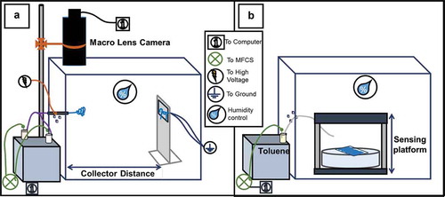
The set-up was kept in a fume hood in order to allow work with volatile organic compounds. The insulating chamber, in which the entire electrospinning process takes place, was created for containing the volume in which the PVP-5CB micro-fibres are collected, and to avoid the fibres from electrostatically adhering to other charged surfaces in the fume hood during their formation.
After the production of the fibre mats, the spinneret and collector were removed, and then the chamber also served as the volume in which gas sensing experiments were performed, as shown in . A vial containing – but not filled with – liquid toluene was closed with a septum, through which two syringe needles were inserted. Both needles ended in the atmosphere above the liquid toluene, one of them nearer to the liquid surface, the other close to the septum. The latter needle was connected to the MFCS pressure control unit, the former needle to a polytetrafluoroethylene (PTFE) tube with open end that was used to manually deliver toluene vapour to the sample. Toluene exposure was initiated by applying pressure to the vial via the MFCS unit, causing the atmosphere above the toluene in the vial, saturated in the solvent vapour, to stream through the PTFE tube towards the sample. By varying the pressure the exposure rate could be varied, albeit without quantitative control of the actual atmosphere at the fibre. When desired, the sample was placed between crossed polarisers to better visualise the optical response of the fibres to toluene exposure. Humidity control was used for both gas sensing and electrospinning experiments, and was varied from 25% to 63%.
3. Results
3.1. Response to toluene vapour of uniformly cylindrical fibres
In contrast to earlier studies, we here investigated the response to gas exposure of the mats as viewed directly, as well as when they are placed between crossed polarisers. While the former response is easier to make use of, provided that it is sufficiently strong and sensitive, it turns out that a mat of LC-filled fibres can respond in two different ways to gas exposure. Because one type of response is detectable only between crossed polarisers, and it is both faster and more sensitive, we initially focus on this configuration. To properly interpret the figures showing the response it is important to note that we, for practical reasons, conducted the macroscopic investigations with the fibre mats placed between crossed polarisers that were some 15 cm apart, without walls on the sides, in a room with daylight illumination. While this allowed convenient access to the samples, for reorienting the mats and initiating and terminating toluene exposure, it also means that considerable stray light entered from the sides, giving a background illumination that reduces the contrast of the response. Moreover, the polarisers used in these experiments were not fully achromatic, giving a blue background colour.
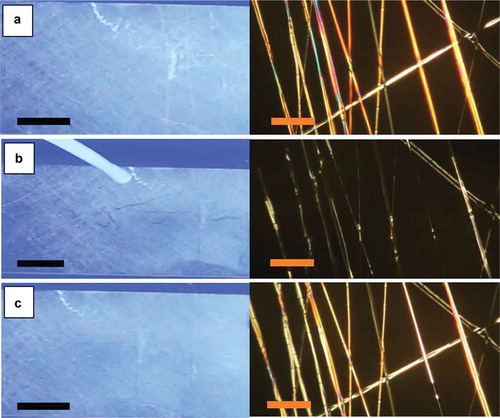
A surprising observation was that a sample with aligned fibres, oriented with the fibre axis along either polariser, was not dark in its ground state (). Considering that the nematic director is assumed to align along the fibre axis, one would not expect to see any effect of LC birefringence in this orientation. While the fibres appeared the darkest in this orientation, they were still clearly brighter than the background. This suggests that the director may in fact have adopted a slightly twisted arrangement, as recently observed for a different type of nematic in cylindrical confinement at larger scale [Citation63,Citation64]. The twist must have been relatively weak, however, since the fibres still became much brighter upon sample reorientation. We will come back to the question of the ground state alignment and the change upon toluene exposure in the discussion in Section 4.
Figure 2. (Colour online) Aligned mat with coaxially spun PVP-LC fibres before (a), during (b) and after (c) exposure to toluene, as observed macroscopically between crossed polarisers (left column; scale bars: 10 mm) and through the POM (right column; scale bars: 80 µm), respectively. The fibres are oriented primarily parallel to the transmission direction of the bottom polariser. The left photos show the large-scale mat between non-achromatic crossed polarisers separated by a large distance, with stray light entering from the sides (hence the blue background colour). All photos are screenshots from Video 1 in the Supplemental Online Material. The screenshots for (b) and (c) were taken immediately during and after exposure, respectively.
Upon localised exposure to toluene vapour from the delivery tube held close to one point of the mat, a much larger area very rapidly lost its brightness, resembling the fibre-free background. The slight remaining difference is due to scattering from the PVP sheath. The effect is best seen in Videos 1 and 2 in the Supplemental Online Material, the left photo in being a representative frame from Video 1. Video 2 shows the same experiment carried out on the same sample, nearly 3 weeks later, confirming that ageing does not affect the response. The toluene delivery tube was held inclined slightly towards the right, such that the sample area to the left of the orifice did not react (same bright appearance as that of the whole mat in ), whereas almost the whole mat to the right of the orifice immediately lost its brightness. As shown in the videos, the response was very fast, no lag being detectable between the motion of the toluene exposure tube and corresponding expansion of the responding area. After toluene exposure was stopped, the original bright state reappeared within about a second (, left pane).
The right column in shows the corresponding experiment carried out in a polarising microscope with the fibres aligned along the polariser. Again the fibres were not dark in the ground state, confirming that the director was not simply aligned along the fibre axis. While the fibre alignment was not perfect, the slight variations in fibre orientation cannot fully explain the bright texture, in particular since even sections aligned exactly along the polariser were not fully dark. Upon toluene vapour exposure, several, albeit not all, of the fibres rapidly turned dark. The toluene exposure in the microscope was less controlled than during the large-scale experiment, hence the reason for some fibres not responding may be local variations in toluene concentration. When the toluene exposure was stopped, the fibres that quickly responded to exposure turned bright again immediately. The fibres with a delayed initial response also relaxed somewhat slower to the bright state.
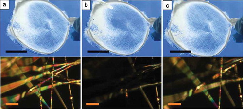
If the aligned sample was reoriented such that the fibres were at 45°angle to the polariser the ground state gained greatly in brightness, as now the effect of the LC birefringence was maximum (). Here, the rapid response seen in is not detectable because the variation in intensity is negligible compared with the high ground state intensity. Instead a stronger response occurs with a considerably greater delay, more localised to the immediate vicinity of the toluene exposure, see and Video 3 in the Supplemental Online Material. In this case, the toluene takes the LC to the isotropic state, removing the birefringence and thereby darkening the fibres in the exposed area. A similar behaviour is seen for the case of a random–aligned mat, as shown in and Video 4 in the Supplemental Online Material. Because many fibres are in an orientation where the LC birefringence gives a considerable effect, regardless of how the macroscopic sample is oriented, the brightness is always on such a high level that the subtle initial response is not discernible, a detectable change appearing only once the LC reaches the isotropic state.
Figure 3. (Colour online) Aligned mat with coaxially spun PVP-LC fibres before (a), during (b) and 6 s after (c) exposure to toluene, as observed macroscopically between crossed polarisers (top row; scale bars: 10 mm) and through the POM (bottom row; scale bars: 80 µm), respectively. The fibres are oriented primarily 45° from the transmission direction of the bottom polariser. The photos in the top row show the large-scale mat between non-achromatic crossed polarisers separated by a large distance, with stray light entering from the sides (hence the blue background colour). All photos are screenshots from Video 3 in the Supplemental Online Material.
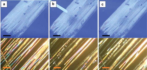
Figure 4. (Colour online) Random mat with coaxially spun PVP-LC fibres before toluene exposure (a), immediately after initiating exposure (b) and immediately after terminating exposure (c), as observed macroscopically between crossed polarisers (left column; scale bars: 10 mm) and through the POM (right column; scale bars: 80 µm), respectively. For the pictures in the left column the mat was placed between non-achromatic crossed polarisers separated by a large distance, with stray light entering from the sides (hence the blue background colour). All photos are screenshots from Video 4 in the Supplemental Online Material.
All samples described so far were collected on glass slides for easy handling, and one might argue that the response could be due to toluene condensing on the glass rather than the vapour entering the LC core. This would mean that it would be liquid rather than gas phase toluene inducing the response. Moreover, the response could then even be due to a modified scattering from the PVP sheath as the air surrounding the PVP is replaced by liquid toluene. To rule out these scenarios, two types of control sample were investigated. First, pure PVP fibres, without any LC filling, were spun on glass slides and exposed to toluene. As shown in the Supplemental Online Material (Figure S3 and Video 5) there was no response observed whatsoever for this case. It clearly demonstrated that the LC is responsible and required for the effect. Second, free-hanging mats containing randomly aligned fibres with LC core were spun using ring-shaped collectors and exposed to toluene while surrounded by only air, see here and Video 6 in the Supplemental Online Material. The response to toluene exposure is essentially identical to that of a randomly aligned mat picked up on a glass slide (the subtle differences are due to the somewhat lower thickness of the free-hanging mat compared to that in ). This proves that it is, indeed, vapour phase toluene that triggers the response and that the presence or absence of a carrier substrate is irrelevant for the effect.
To test for long-term stability of the liquid crystal-functionalised fibre sensors we repeated the experiments after several weeks of storage. In fact, and and Videos 1–3 show the very same aligned fibre mat, the difference being its age. In and Video 1 the sample is rather new, the experiment carried out less than 1 week after electrospinning the fibres. By the time the experiments in and Videos 2–3 were carried out, about a month had passed since the production of the mat, and it had been subjected to various experiments in the meantime, resulting in some damage, as can be seen in the photos. The fact that exactly the same type of response is seen for the same experiment on a mat when it was new and when it was aged (Videos 1 and 2) proves that neither the ageing, nor the damage to the fibres, had any adverse effect on the gas sensing capability.
Our current toluene exposure procedure is convenient in many respects but it neither produces a uniform toluene concentration over the entire mat, nor does it allow us to calculate what the concentration is. Poorly controlled gradients in time and space are present, the toluene concentration being the greatest at the orifice of the tube used to deliver the vapour. As the experiments were done in an open environment, with the sample placed in a fume hood, the concentration rapidly falls off away from the orifice. We can, however, use the vapour pressure of toluene at the temperature at which the experiments were carried out to obtain an upper estimate for the toluene concentration (details in the Supplemental Online Material). While this dramatically overestimates the actual level of exposure for the fibre mat, it at least allows a first establishment of the regime in which the response takes place. This simple method results in an upper limit for the concentration of about 3%, the real threshold for response clearly being substantially lower. We are currently in the process of constructing a tailor-made sample chamber, similar to that used by Abbott et al. [Citation32], in order to accurately determine the detection level. The results will be reported in a future publication.
3.2. Response to toluene vapour of irregular, beaded, fibres
Without the use of crossed polarisers, the response to toluene gas exposure of the samples discussed so far could not be detected. As shown in the POM images in – these samples all have well formed uniformly cylindrical fibres. However, with appropriate modifications of the spinning parameters the fibre morphology can be changed to an irregular shape, where beads appear along the cylindrical base fibres. It turns out that mats with such fibres show a response that is visible even without polarisers, as will be described in this section.
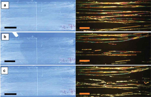
Figure 5. (Colour online) Random free-hanging mat with coaxially spun PVP-LC fibres before (a), during (b) and after (c) exposure to toluene, as observed macroscopically between crossed polarisers (top row; scale bars: 10 mm) and through the POM (bottom row; scale bars: 80 µm; the local lack of focus is due to the varying height of the free-hanging fibres), respectively. All photos are screenshots from Video 6, (b) and (c) taken immediately after initiating and after terminating exposure, respectively. Importantly, no substrate was in contact with the fibres during the experiments. The photos in the top row show the large-scale mat between non-achromatic crossed polarisers separated by a large distance, with stray light entering from the sides (hence the blue background colour).
We explored two methods for producing these irregular fibres. The first method involves increasing the LC core flow rate strongly, to the point where it was 67% higher than the flow rate of the polymer solution that formed the sheath (our standard flow rate ratio was 5:9). With such a strong core flow, the entangled polymer chains in the sheath solution could not fully suppress the Rayleigh instability taking place in the core fluid. This resulted in fibres that were still unbroken and continuous, but richly decorated with protruding beads, as shown in the optical microscopy images in ,). Some fibres also had a strongly increased average thickness. In the second method, we kept the usual 5:9 ratio of LC and polymer solution flow rates but we instead increased the humidity level, from the usual % to 61% during spinning. It was reported in a previous study [Citation65] that a relative humidity during electrospinning greater than 30% will tend to induce beading, as well as merging, of PVP fibres. The high humidity prevents a rapid evaporation of the solvent from the sheath solution. This extends the time frame over which a Rayleigh instability can induce beading of the initially cylindrical fibres, and as the fibres are still wet when they land on the target substrate, they also have time to merge prior to solidification. Our fibres spun under such humid conditions are shown in the lower row of . While the average fibre thickness is lower than for the other beaded fibre morphology, it is still greater than that of fibres spun in dry atmosphere and the beaded morphology is strongly pronounced. Importantly, while both fibre types are heavily irregular, there is no leakage of LC outside the PVP sheath.
Figure 6. (Colour online) Optical microscopy images of irregular LC-filled fibre mats. The upper row corresponds to the left column in , the fibres spun with an LC-to-polymer solution flow rate ratio of 15:9. Panel A is taken between crossed polarisers, panel B without the analyser. The lower row shows the sample spun with an LC-to-polymer solution flow rate ratio of 5:9 but in high relative humidity (61%), thus corresponding to the right column in . All scale bars indicate 100 µm.
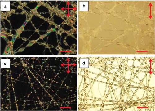
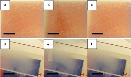
Figure 7. (Colour online) Macroscopic response to toluene exposure of the mats with irregular coaxial PVP-LC fibres (microscope photos are shown in ). The left column images are of the mat spun at 15:9 LC:PVP solution flow rate ratio, before (a), during (b) and 13 s. after (c) gas exposure. The right column shows the corresponding images for the mat spun with 5:9 LC:PVP solution flow rate ratio but at elevated relative humidity (61%), before (d), during (e) and 13 s. after (f) gas exposure. Scale bars: 10 mm.
The macroscopic responses to toluene vapour from the two mat types with irregular fibre morphology are shown in . The three rows correspond to the appearance between crossed polarisers (the response without polarisers will be described below) before, during and after toluene exposure. The mat in the left column was spun with increased LC flow rate, the mat in the right column with increased humidity. As usual, the photos are screenshots from videos, included in the Supplemental Online Material as Video 7 and Video 8, respectively. Both mats respond on the time scale of a second to the toluene exposure in areas with appropriate thickness, with the response of the mat spun with high LC flow rate being by far the strongest. This may be rationalised as a result of the much greater degree of LC filling in many fibres in this mat, several sections reaching local diameters up to nearly 20 µm. While it takes slightly longer for such richly filled fibres to respond to the gas exposure, and to relax after termination of the exposure, the visible contrast between ground state and exposed state is by far the greatest among all mats explored. The response in the high-humidity sample is somewhat weaker, also because it contains an area where the mat is too thick for the response to be clearly visible.
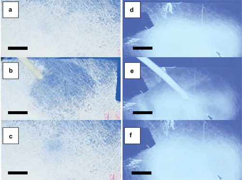
Interestingly, both types of mat with irregular fibres also show gas sensing responses without crossed polarisers, as shown in here and in real time in Videos 9 and 10 of the Supplemental Online Material. The mats are placed over a coloured background, allowing the response to be detected as a reduction in scattering, making the background colour more apparent. When the same type of experiment was conducted on the mats with regular cylindrical fibres, the response was not detectable; for the response to be visible, these mats had to be placed between crossed polarisers. The fact that the response can become visible without polarisers is obviously of great value for applications in textile-integrated sensors, where a background image, becoming visible upon gas exposure, could be easily incorporated. By further optimising the fibre morphology based on the new understanding resulting from this work, replacing also the 5CB and PVP model materials by LC and polymer tailored for the purpose, we are confident that the contrast can be enhanced and the sensitivity improved, as discussed towards the end of the paper. The incorporation of crossed polarisers, as required to utilise the cylindrical fibres, would also be possible, since also polarisers good enough for use with liquid crystal cells can be electrospun [Citation66]. However, this approach would complicate the construction of the sensor, which then would have to include a reflective background cloth for allowing a visible response in ambient light.
Figure 8. (Colour online) Macroscopic images, obtained without polarisers, of coaxial PVP-LC fibre mats spun at 25% relative humidity with a 15:9 LC:PVP flow rate ratio, before (a), during (b) and 13 s. after (c) gas exposure, and of coaxial PVP-LC fibre mats spun at 61% relative humidity with a 5:9 LC:PVP flow rate ratio, before (d), during (e) and 13 s. after (f) gas exposure. Scale bars: 10 mm.
3.3. Nanoscale characterisation of fibre sheath morphology
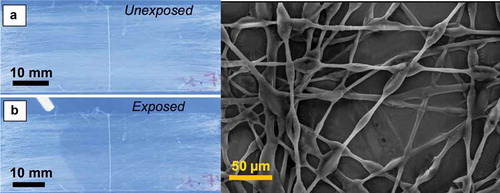
To further gain a more detailed knowledge of the fibre morphology, the various fibre mats described above were subjected to SEM investigation, after coating with a thin layer of gold to avoid charge build-up during imaging. An overview of the main results is provided in . With the SEM we were able to measure the fibre diameters with high precision, finding that all prepared fibres have a base diameter in the range of 4–7 µm. The SEM investigations do not allow us to distinguish core from sheath size, a task that requires sectioning of the fibres by Focused Ion Beam (FIB) prior to imaging of the cross section [Citation51,Citation67], but the POM images shown above demonstrate that the LC filling was rather high. This suggests that the fibre cross section is dominated by the LC core for all fibres. In the next section and in the Supplemental Online Material we discuss how the core-sheath ratio can be conveniently tuned by changing the flow rates of the two fluids used for the coaxial spinning.
Figure 9. (Colour online) SEM images of LC-filled PVP fibre mats prepared at varying conditions. The images in the upper row all show mats spun in a dry atmosphere (25–28% relative humidity) and with a 5:9 LC:PVP solution flow rate ratio. The fibres in (a) were collected with random order, whereas those in (b) and (c) show aligned fibres. A free-hanging mat of random-oriented fibres, spun with the same flow rate ratio but slightly higher humidity (43%), is shown in (d). Image (e) shows random-oriented fibres spun in dry atmosphere (about 25%) but at 15:9 LC:PVP solution flow rate ratio, whereas (f) shows a random mat spun with 5:9 LC:PVP solution flow rate ratio but at 61% relative humidity. The scale bars for (a), (b), (d) and (e) are 50 µm, whereas those for (c) and (f) are 2 µm and 20 µm, respectively.
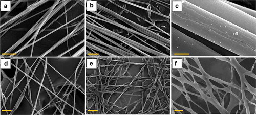
For the irregular fibres (,)), there are dramatic local increases in diameter, as seen already from the POM images. With the higher precision from the SEM images we estimate that the beads have a typical maximum diameter of about 16–20 µm. We now also see an important difference between the two beaded mats. While the humid atmosphere during spinning caused the fibres in to merge at essentially all crossing points (a result of the liquid state upon collection of the fibres), fibre merging is rare in . This means that the fibre sheath was close to solid prior to collection, as expected for spinning in a dry atmosphere. Based on an earlier observation of suppressed core filling in crossing points where fibres merged [Citation51], one may thus conclude that high LC flow rate and dry atmosphere is probably the ideal approach to produce irregular, beaded, fibres, without suffering too much fibre merging.
Finally, the close-up in reveals that the sheath of the uniformly cylindrical fibres was in fact quite porous. This porosity may be important in assisting the passage of toluene into the LC core. The pores mostly resemble ovals elongated along the fibre axis, with lengths averaging to about 200 ± 6 nm, for 19 measurements made throughout the image seen.
4. Discussion
4.1. Origin of the optical response to toluene vapour exposure
We can distinguish between at least two types of response seen from the liquid crystal-filled fibres to toluene exposure; one immediate but subtle, and one somewhat slower but stronger, as described in Section 3. The best demonstration of the two response modes is by comparing Videos 2 and 3, which show the same mat held at two different orientations with respect to the polarisers. In Video 2, a subtle but basically instantaneous response is seen over a large sample area, when the fibres are aligned along the polariser. If the fibres are instead aligned 45° to the polariser, as in Video 3, it takes much longer time before a response can be detected. The response that is now visible is more localised to the exact point of exposure, but the contrast is stronger.
Most likely, the latter type of response corresponds to the nematic-isotropic (clearing) transition of the LC core. The toluene vapour enters through the PVP polymer sheath to access the LC core, where it acts as an impurity for the 5CB. As such, the toluene molecules diffusing into the 5CB lower the clearing temperature of the nematic to below 35.4°C, even below room temperature once the concentration is sufficient. At this point the core turns isotropic and the birefringence disappears, with a consequent change in optical appearance between crossed polarisers. Upon termination of toluene exposure, the volatile toluene molecules again leave the 5CB core through the PVP sheath, allowing the LC to rebuild the nematic phase. The core again becomes birefringent, and thus turns bright between crossed polarisers when the fibres are aligned around 45° to either polariser.
It is also this phase transition of the core material that gives rise to the response from the irregular fibres, visible without polarisers as shown in and Videos 9–10. The effect is related to a reduced degree of scattering upon the phase transition from nematic to isotropic. Since this effect is seen for beaded fibres, we conjecture that the scattering is due to the strong local variations in director orientation, and thus in optic axis orientation, within the beads. This differs from the director orientation in the cylindrical fibres, where it is largely (but not completely) uniformly oriented along the fibre. Thus, each bead scatters light strongly in the nematic state, but when the bead content turns isotropic it becomes optically uniform with the remaining scattering due to the refractive index changes at the inner and outer PVP interfaces.
This would mean that the varied scattering effect is actually very similar to the case of polymer-dispersed liquid crystal (PDLC) films [Citation68,Citation69], where LC droplets contained in a continuous polymer matrix are switched between clear and scattering states via application or removal of an electric field. With beaded fibres we can thus reproduce this effect without the need for a continuous polymer matrix. In contrast to a PDLC, a free-hanging non-woven electrospun mat is perfectly breathable thanks to the large gaps between fibres, thus rendering it highly useful as a responsive textile mat for wearable technology applications. However, materials optimisation is needed, on the one hand to match the refractive index of the isotropic LC to that of the polymer, on the other hand to find a polymer that is appropriate for textiles. PVP is a useful model polymer, convenient for the electrospinning experiments described here, but its hygroscopic and brittle character is not appropriate for the envisaged applications in wearable technology.
At present we can only speculate as to the origin of the much faster response seen when the mat is between crossed polarisers with the fibre direction along either polariser. As mentioned above, the fact that the fibre mat is not dark to begin with indicates that the director does not align fully along the fibre mat, in contrast to what was previously reported [Citation53,Citation54,Citation59]. In our fibres, there must be a slight non-uniformity in the director field that renders the fibres bright in the ground state. A possible explanation may be the tendency for a twist to develop when a nematic with non-negligible saddle-splay elastic constant is confined cylindrically with planar anchoring at the boundaries. This surprising phenomenon was recently reported, for much larger-scale cylindrical capillaries, for chromonic lyotropic nematics [Citation63,Citation64]. For such a twist to develop,
should be large and the twist elastic constant,
, should be weak [Citation63]. In our fibres, the nematic is thermotropic 5CB, which typically does not fulfil these criteria [Citation63]. However, the cylindrical confinement is much stronger here and the twist – if present – is much weaker; in the study by Nayani et al. [Citation63] the capillary appeared almost identical parallel and at 45° to the polariser, in stark contrast to the fibres studied here. Hence the effect may be qualitatively the same, only much less pronounced.
In a recent study by the Abbot group, exposure to toluene already at very low concentrations was shown to have a dramatic effect on the LC anchoring strength, such that any unfavourable elastic deformation induced by the anchoring is removed upon toluene exposure [Citation32]. Applying this knowledge to our case, under the assumption that the planar anchoring and cylindrical confinement has induced a slight twist, we conjecture that the toluene exposure of our fibres leads to an almost immediate loss of defined anchoring geometry, allowing the liquid crystal to remove the twist to reduce its free energy. This would explain the rapid reduction in brightness seen upon toluene exposure in . This conjecture needs to be corroborated in future work, but if it is correct, it provides an interesting opening for enhancing the effect.
4.2. How does the toluene vapour access the LC core?
A critical issue for the proposed concept of gas sensors is the thickness and quality of the polymer sheath. Clearly, we must find a trade-off between conflicting requirements; the sheath must be thick and durable enough to securely contain the liquid crystal, yet it should be as thin and porous as possible in order to ensure easy and rapid access of the analyte to the LC core.
For tuning the sheath thickness, the key spinning parameter is the ratio between flow rates of LC to polymer solution. In the Supplemental Online Material, we carry out a simple estimation of how the change from 5:9 to 15:9 core-sheath flow rate ratios affects the sheath thickness. Under the simplifying assumption that both fluids move together throughout the jet, allowing us to apply volume conservation for a small section, we find that the sheath thickness at 15:9 ratio would be at most 65% of the sheath thickness at 5:9 ratio. As discussed in the Supplemental Online Material, we expect this to be a rather grave overestimate due to the simplifying assumptions made. A reasonable expectation may be that the sheath thickness is at least an order of magnitude thinner at 15:9 than at 5:9 flow rate ratio.
Since the increase in LC flow rate leads to an expansion of the core radius, with a consequent quadratic increase in interfacial area between core and sheath fluids, the energy of the interface between liquid crystal and polymer solution also increases. Taking this situation into account, it is not surprising that a Rayleigh instability builds up in the core when spinning with 15:9 flow rate ratio, resulting in the beaded fibre morphology shown in and .
An intriguing question is why also the humid atmosphere leads to thicker fibres with beaded morphology. To understand this phenomenon, first, the effects of humid air on the PVP solution need to be accounted for. Normally, when spinning in a dry atmosphere, there is a net flux of solvent (ethanol in our case) evaporating from the sheath solution. While this occurs, there are also electrostatic forces acting on ions in the solution which induce stretching of the jet [Citation56,Citation70,Citation71]. As a result, the polymer chains must adopt conformations that are extended along the jet, and these non-equilibrium conformations are then frozen in a glassy state when a sufficient fraction of the ethanol has evaporated.
When spinning in humid conditions, water from the atmosphere enters the jet during spinning, mixing with the ethanol–PVP solution. This has multiple interesting consequences. First, rather than a net solvent flux out of the sheath solution we may have a net solvent flux into the solution, at least during a certain stage of the spinning process. The added water will swell the sheath, which on the time scale of the spinning procedure requires the polymer chains to adopt extended conformations, since they are heavily entangled (the molar mass of the polymer must be high enough to ensure entanglements in any polymer fibre spinning process, as otherwise the jet would not be stable [Citation72,Citation73]). If the electric field were absent, the swelling and consequent polymer chain extension would be isotropic, but in this case the polymer conformation is already extended along the jet due to the stretching action of the electric field. As a consequence, water-induced further swelling in that direction becomes entropically very costly [Citation74]. Thus, we should primarily expect expansion perpendicular to the jet.
Second, the high dielectric constant of water enhances the screening of the externally applied electric field. This means that the effective stretching force acting on the jet is reduced. Considering both effects (which are not independent; the latter counteracts the former to some extent) we can expect a reduction in jet stretching while spinning in a humid atmosphere compared to spinning in dry conditions. This suggests that both core and sheath cross sections expand during spinning, but the final situation in the dry fibre may be quite different for core and sheath. The core cross section should experience no significant reduction beyond that due to jet stretching, since no solvent evaporates from the LC. In contrast, the sheath cross section should reduce considerably upon fibre solidification, having been expanded in the wet state by its own solvent and water from the atmosphere. In other words, we end up with a surprisingly similar situation of expanded core cross section area and reduced sheath thickness as in the case of 15:9 flow rate ratio spinning in a dry atmosphere, although the mechanism giving rise to the phenomenon is very different. We have the counterintuitive situation where a humidity-induced expansion of the sheath thickness during spinning triggers a chain of events that eventually lead to a reduction in sheath thickness and increase in core diameter. Again, with increasing core-sheath interfacial area the Rayleigh instability is promoted, and we see beading of the fibres. Additionally, here we see considerable merging of the fibres since they are still wet when they reach the target substrate.
An interesting observation from the SEM characterisation in Section 3.3 is that pores are seen in the sheaths of fibres spun in dry atmosphere, but not in those of fibres spun in wet atmosphere, or with increased LC flow rate. Since the latter two both responded to toluene exposure, with an effect visible even without polarisers, this shows that a porous sheath is not a requirement when using liquid crystal core fibres for gas sensing. The sheath is thin enough in these fibres to allow the toluene to reach the core, albeit perhaps slower than through a porous sheath. In the fibres spun in humid atmosphere, we actually found a few cracks in the sheaths, an example shown in Figure S5 in the Supplemental Online Material. However, they occurred so infrequently that it is unlikely that they would play a major role in the response observed.
While pores are thus not necessary for the gas response, they are certainly an advantage. In fact, we hypothesise that their presence in the sheaths of the uniformly cylindrical fibres spun in dry atmosphere may be critical for their very rapid response between crossed polarisers, as in . Therefore, it presents an interesting question as to what the origin of the pores is. Previous reports of high porosity in electrospun fibres dealt with hydrophobic polymers, like polystyrene (PS), polymethylmethacrylate (PMMA) or polycarbonate (PC) [Citation60–Citation62]. In all of these cases, the porosity was triggered by spinning in a humid atmosphere, which led to condensation of water droplets on the fibre during spinning. As the water is not a solvent for the polymers, the water droplet remained as a lens-shaped inclusion at the wet surface, leaving a porous imprint after the polymer had dried and the water evaporated.
In contrast, the PVP used as fibre sheath in this study is hygroscopic. Rather than water condensing to make surface-anchored inclusions, the water from a humid atmosphere distributes throughout the polymer solution and swells the whole sheath. Thus, the water does not induce pore formation but may even, on the contrary, contribute to the closing of pores, because it keeps the polymer solution in a wet state longer than when fibres are spun in a dry atmosphere. As to the origin of the pores in , this is far from obvious, but we may assume that it is similar to the situation in our earlier study where porous PVP sheaths were detected [Citation58]. The pores only appeared in fibres that had been spun in an atmosphere that was saturated in the ethanol used for dissolving the polymer, suggesting that the pore formation may have been a result of ethanol recondensation at a late stage of the spinning process.
4.3. Opportunities for enhancing sensitivity and specificity of the response
The experiments in the present work confirm the potential of using liquid crystal-filled fibres for non-electronic gas sensing. Our observations also give some valuable hints concerning the route towards increasing the sensitivity of the response, by keeping the thickness thin and, preferably, porous, and by demonstrating that multiple response modes exist. The Abbott group work has clearly demonstrated the advantages of a response mode that is based on a realignment triggered by an anchoring change at the interface, allowing very high sensitivity. The very fast response seen in is promising in this context, as it appears, as discussed above, that it involves an interface rather than a bulk response, allowing the sensing threshold to be kept very low.
The important question of specificity of the response is beyond the scope of the present work, but we may suggest some guidelines on how to approach this challenge. We believe that a promising strategy is to sensitise the liquid crystal-filled polymer fibres with appropriate additives that give a local specific response to the desired analyte, in such a way that the local response is amplified by the liquid crystal into an optically detectable response. The viability of this approach has been demonstrated in non-fibrous LC-based gas sensors by the Abbott group [Citation33,Citation34,Citation43,Citation44] and by the team of Broer and Sijbesma [Citation19].
Lastly, we would like to emphasise that the coaxial electrospinning method for creating these fibre mats is not a fabrication requirement, to our current knowledge. The coaxial electrospinning set-up has small footprint, is inexpensive, allows fast fibre fabrication and is easy to customise in various ways for different experiments, making it ideal for laboratory research. For future scale-up and more applied studies, however, other coaxial fibre spinning techniques may be more practical, in particular for fabricating viable textile devices.
5. Conclusions
Composite fibres consisting of a thin, preferably porous, polymeric sheath, surrounding a liquid crystal core with radius on the order of a few microns, show potential for non-electronic sensing and detection of volatile organic compounds. We have demonstrated that mats of electrospun fibres with PVP sheath surrounding a core of nematic 5CB change their optical properties within seconds when exposed to toluene vapour, yielding a modification of macroscopic appearance that is visible to the naked eye. No visible change in the response was found over a month, suggesting that the sensing function of the fibres is stable over long time. The visualisation of the response was greatly enhanced by placing the mat between crossed polarisers, allowing the detection of a very rapid and sensitive response from fibres with uniform cylindrical morphology. This response is most likely due to a change in surface anchoring at the 5CB–PVP interface, with consequent reorganisation of the bulk liquid crystal director field. Interestingly, the behaviour of these fibres suggests a slightly twisted ground state director configuration within the cylindrical confinement prior to exposure.
When the fibres were given a beaded morphology and a base diameter of at least 6–7 µm, the response was even visible without crossed polarisers, as reduced light scattering upon exposure by toluene. We propose that this is due to the isotropisation of the 5CB inside the beads, with an effect that is similar to that of polymer-dispersed liquid crystals. Importantly, the response of the mat was independent of whether a substrate is present or not, free-hanging fibre mats responding in the same way as mats deposited on glass slides. This means that, once the PVP has been replaced by an appropriate textile-grade polymer, liquid crystal-functionalised fibres could be incorporated as wearable gas sensors in garments worn by persons at risk of being exposed to hazardous gases. The key outstanding challenges are to provide specificity to a particular gas of interest and to reduce the threshold for a visible response. We have outlined possible approaches to reach these important goals, after which liquid crystal-functionalised fibres could be turned into wearable gas sensors that function at room temperature and without any power supply, opening vast application opportunities in numerous fields.
Video_10_-_correct-title.mov
Download QuickTime Video (4.1 MB)Video_9_correct-title
Download QuickTime Video (2.8 MB)Video_8_correct-title
Download QuickTime Video (2.3 MB)Video_7_correct_title
Download QuickTime Video (3.8 MB)Supplemental_data
Download PDF (1.3 MB)Disclosure statement
No potential conflict of interest was reported by the authors.
Supplementary material
Supplemental data (sensor response videos, further experimental details and some additional data) for this article can be accessed here.
Additional information
Funding
Related Research Data
References
- Kohl D. Function and applications of gas sensors. J Phys D Appl Phys. 2001;34(19):R125–R149. doi:10.1088/0022-3727/34/19/201.
- Liu X, Cheng S, Liu H, et al. A survey on gas sensing technology. Sensors. 2012;12(12):9635–9665. doi:10.3390/s120709635.
- Moseley PT. Solid state gas sensors. Meas Sci Technol. 1997;8(3):223–237. doi:10.1088/0957-0233/8/3/003.
- Yamazoe N. Toward innovations of gas sensor technology. Sens Actuators B. 2005;108(1–2):2–14. doi:10.1016/j.snb.2004.12.075.
- Bakhoum EG, Cheng MHM. Miniature carbon monoxide detector based on nanotechnology. IEEE Trans Instrum Meas. 2013;62(1):240–245. doi:10.1109/TIM.2012.2212507.
- McDonald EM, Gielen AC, Shields WC, et al. Residential carbon monoxide (CO) poisoning risks: correlates of observed CO alarm use in urban households. J Environ Health. 2013;76(3):26–32.
- Billi E, Viricelle JP, Montanaro L, et al. Development of a protected gas sensor for exhaust automotive applications. IEEE Sens J. 2002;2(4):342–348. doi:10.1109/JSEN.2002.804530.
- Riegel J. Exhaust gas sensors for automotive emission control. Solid State Ionics. 2002;152-153:783–800. doi:10.1016/S0167-2738(02)00329-6.
- Diehl KL, Anslyn EV. Array sensing using optical methods for detection of chemical and biological hazards. Chem Soc Rev. 2013;42(22):8596. doi:10.1039/c3cs60136f.
- Yoo R, Kim J, Song MJ, et al. Nano-composite sensors composed of single-walled carbon nanotubes and polyaniline for the detection of a nerve agent simulant gas. Sens Actuators B. 2015;209:444–448. doi:10.1016/j.snb.2014.11.137.
- Kim DK, Hwang M, Lagerwall JPF. Liquid crystal-functionalization of electrospun polymer fibers. J Polym Sci B Polym Phys. 2013;51(11):855–867. doi:10.1002/polb.23285.
- Smulko JM, Trawka M, Granqvist CG, et al. New approaches for improving selectivity and sensitivity of resistive gas sensors: a review. Sensor Rev. 2015;35(4):340–347. doi:10.1108/SR-12-2014-0747.
- Yu JB, Byun HG, So MS, et al. Analysis of diabetic patient’s breath with conducting polymer sensor array. Sens Actuators B. 2005;108(1–2):305–308. doi:10.1016/j.snb.2005.01.040.
- Kim J, Lee M, Shim HJ, et al. Stretchable silicon nanoribbon electronics for skin prosthesis. Nat Commun. 2014;5:5747. doi:10.1038/ncomms6747.
- Borini S, White R, Wei D, et al. Ultrafast graphene oxide humidity sensors. ACS Nano. 2013;7(12):11166–11173. doi:10.1021/nn404889b.
- Ramgir N, Datta N, Kaur M, et al. Metal oxide nanowires for chemiresistive gas sensors: issues, challenges and prospects. Colloid Surf A. 2013;439:101–116. doi:10.1016/j.colsurfa.2013.02.029.
- Drean E, Schacher L, Bauer F, et al. A smart sensor for induced stress measurement in automotive textiles. J Text I. 2007;98(6):523–531. doi:10.1080/00405000701502404.
- Franke M, Simon U, Moos R, et al. Development and working principle of an ammonia gas sensor based on a refined model for solvate supported proton transport in zeolites. Phys Chem Chem Phys. 2003;5(23):5195–5198. doi:10.1039/B307502H.
- Han Y, Pacheco K, Bastiaansen CWM, et al. Optical monitoring of gases with cholesteric liquid crystals. J Am Chem Soc. 2010;132(9):2961–2967. doi:10.1021/ja907826z.
- Wang L, Chen W, Xu D, et al. Simple, rapid, sensitive, and versatile SWNT-paper sensor for environmental toxin detection competitive with ELISA. Nano Lett. 2009;9(12):4147–4152. doi:10.1021/nl902368r.
- Bandodkar A, Molinnus D, Mirza O, et al. Epidermal tattoo potentiometric sodium sensors with wireless signal transduction for continuous non-invasive sweat monitoring. Biosens Bioelectron. 2014;54:603–609. doi:10.1016/j.bios.2013.11.039.
- Bergmann J, McGregor A. Body-worn sensor design: what do patients and clinicians want. Ann Biomed Eng. 2011;39(9):2299–2312. doi:10.1007/s10439-011-0339-9.
- Bonato P. Wearable sensors and systems. from enabling technology to clinical applications. IEEE Eng Med Biol Mag. 2010;29(3):25–36. doi:10.1109/MEMB.2010.936554.
- Chan M, Estève D, Fourniols J, et al. Smart wearable systems: current status and future challenges. Artif Intell Med. 2012;56(3):137–156. doi:10.1016/j.artmed.2012.09.003.
- Shim B, Chen W, Doty C, et al. Smart electronic yarns and wearable fabrics for human biomonitoring made by carbon nanotube coating with polyelectrolytes. Nano Lett. 2008;8(12):4151–4157. doi:10.1021/nl801495p.
- Korotcenkov G. Handbook of gas sensor materials: properties, advantages and shortcomings - volume 1: conventional approaches gas sensor requirements. In: Potyrailo RA, editor. Handbook of gas sensor materials. Vol. 1. New York (NY): Springer-Verlag; 2013. p. 26–35.
- Comini E, Faglia G, Sberveglieri G, et al. Stable and highly sensitive gas sensors based on semiconducting oxide nanobelts. Appl Phys Lett. 2002;81(10):1869. doi:10.1063/1.1504867.
- Fine GF, Cavanagh LM, Afonja A, et al. Metal oxide semi-conductor gas sensors in environmental monitoring. Sensors. 2010;10(6):5469–5502. doi:10.3390/s100605469.
- Yamazoe N. New approaches for improving semiconductor gas sensors. Sens Actuators B. 1991;5(1–4):7–19. doi:10.1016/0925-4005(91)80213-4.
- Bochenkov VE, Sergeev GB. Metal oxide nano-structures and their applications sensitivity, selectivity, and stability of gas-sensitive metal-oxide nanostructures. In: Umar A, Hahn YB, editors. Metal oxide nanostructures and their applications. Vol. 2(3). Valencia (CA): American Scientific Publishers; 2010. p. 31–52.
- Pang C, Lee C, Suh K. Recent advances in flexible sensors for wearable and implantable devices. J Appl Polym Sci. 2013;130(3):1429–1441. doi:10.1002/app.v130.3.
- Bedolla-Pantoja M, Abbott N. Surface-controlled orientational transitions in elastically strained films of liquid crystal that are triggered by vapors of toluene. ACS Appl Mater Interfaces. 2016;8:13114–13122. doi:10.1021/acsami.6b02139.
- Jacob HT, Nicholas AL. Dynamics of the chemo-optical response of supported films of nematic liquid crystals. Sens Actuators B. 2013;183:71–80. doi:10.1016/j.snb.2013.03.094.
- Hunter JT, Pal SK, Abbott NL. Adsorbate-induced ordering transitions of nematic liquid crystals on surfaces decorated with aluminum perchlorate salts. ACS Appl Mater Interfaces. 2010;2(7):1857–1865. doi:10.1021/am100165a.
- Carlton RJ, Hunter JT, Miller DS, et al. Chemical and biological sensing using liquid crystals. Liq Cryst Rev. 2013;1(1):29–51. doi:10.1080/21680396.2013.769310.
- Chang CK, Kuo HL, Tang KT, et al. Optical detection of organic vapors using cholesteric liquid crystals. Appl Phys Lett. 2011;99(7):073504. doi:10.1063/1.3627162.
- Chen CH, Lin YC, Chang HH, et al. Ligand-doped liquid crystal sensor system for detecting mercuric ion in aqueous solutions. Anal Chem. 2015;87(8):4546–4551. doi:10.1021/acs.analchem.5b00675.
- Giese M, De Witt JC, Shopsowitz KE, et al. Thermal switching of the reflection in chiral nematic mesoporous organosilica films infiltrated with liquid crystals. ACS Appl Mater Interf. 2013;5(15):6854–6859. doi:10.1021/am402266z.
- Liu Y, Cheng D, Lin IH, et al. Microfluidic sensing devices employing in situ-formed liquid crystal thin film for detection of biochemical interactions. Lab Chip. 2012;12(19):3746–3753. doi:10.1039/c2lc40462a.
- Wang D, Park SY, Kang IK. Liquid crystals: emerging materials for use in real-time detection applications. J Mater Chem C. 2015;3(35):9038–9047. doi:10.1039/C5TC01321F.
- Wang PH, Yu JH, Zhao YB, et al. A novel liquid crystal-based sensor for the real-time identification of organophosphonate vapors. Sens Actuators B. 2011;160(1):929–935. doi:10.1016/j.snb.2011.09.005.
- Dickert F, Haunschild A, Hofmann P. Cholesteric liquid-crystals for solvent vapor detection - elimination of cross-sensitivity by band shape-analysis and pattern-recognition. Fresenius J Anal Chem. 1994;350(10–11):577–581. doi:10.1007/BF00323506.
- Cadwell KD, Lockwood NA, Nellis BA, et al. Detection of organophosphorous nerve agents using liquid crystals supported on chemically functionalized surfaces. Sens Actuators B. 2007;128(1):91–98. doi:10.1016/j.snb.2007.05.044.
- Sridharamurthy S, Cadwell K, Abbott N, et al. A microstructure for the detection of vapor-phase analytes based on orientational transitions of liquid crystals. Smart Mater Struct. 2008;17(1):012001. doi:10.1088/0964-1726/17/01/012001.
- Cheng D, Sridharamurthy SS, Hunter JT, et al. A sensing device using liquid crystal in a micropillar array supporting structure. J Microelectromech Syst. 2009;18(5):973–982. doi:10.1109/JMEMS.2009.2029977.
- Herzer N, Guneysu H, Davies JD, et al. Printable optical sensors based on h-bonded supramolecular cholesteric liquid crystal networks. J Am Chem Soc. 2012;134(18):7608–7611. doi:10.1021/ja301845n.
- Mujahid A, Stathopulos H, Lieberzeit A, et al. Solvent vapour detection with cholesteric liquid crystals-optical and mass-sensitive evaluation of the sensor mechanism. Sensors. 2010;10(5):4887–4897. doi:10.3390/s100504887.
- Sutarlie L, Qin H, Yang KL. Polymer stabilized cholesteric liquid crystal arrays for detecting vaporous amines. Analyst. 2010;135(7):1691–1696. doi:10.1039/b926674g.
- Lin J, Chen C, Chen L, et al. Morphological appearances and photo-controllable coloration of dye-doped cholesteric liquid crystal/polymer coaxial microfibers fabricated by coaxial electrospinning technique. Opt Express. 2016;24(3):3112–3126. doi:10.1364/OE.24.003112.
- Wang J, Jákli A, West J. Airbrush formation of liquid crystal/polymer fibers. ChemPhysChem. 2015;16:1839–1841. doi:10.1002/cphc.v16.9.
- Enz E, La Ferrara V, Scalia G. Confinement-sensitive optical response of cholesteric liquid crystals in electrospun fibers. ACS Nano. 2013;7(8):6627–6635. doi:10.1021/nn400066n.
- Ebru BA, Margaret FW, John WL. Self-assembled, optically responsive nematic liquid crystal/polymer core-shell fibers: Formation and characterization. Polymer. 2010;51(21):4823–4830. doi:10.1016/j.polymer.2010.08.011.
- Enz E, Lagerwall J. Electrospun microfibres with temperature sensitive iridescence from encapsulated cholesteric liquid crystal. J Mater Chem. 2010;20(33):6866–6872. doi:10.1039/c0jm01223h.
- Lagerwall JPF, McCann JT, Formo E, et al. Coaxial electrospinning of microfibres with liquid crystal in the core. Chem Commun. 2008;42:5420–5422. doi:10.1039/b810450f.
- Agarwal S, Greiner A, Wendorff JH. Electrospinning of manmade and biopolymer nanofibers - progress in techniques, materials, and applications. Adv Funct Mater. 2009;19(18):2863–2879. doi:10.1002/adfm.v19:18.
- Reneker D, Yarin A. Electrospinning jets and polymer nanofibers. Polymer. 2008;49(10):2387–2425. doi:10.1016/j.polymer.2008.02.002.
- Li D, Xia Y. Electrospinning of nanofibers: reinventing the wheel? Adv Mater. 2004;16(14):1151–1170. doi:10.1002/(ISSN)1521-4095.
- Scalia G, Enz E, Calò O, et al. Morphology and core continuity of liquid-crystal-functionalized, coaxially electrospun fiber mats tuned via the polymer sheath solution. Macromol Mater Eng. 2013;298(5):583–589. doi:10.1002/mame.201200361.
- Enz E, Baumeister U, Lagerwall J. Coaxial electrospinning of liquid crystal-containing poly(vinyl pyrrolidone) microfibers. Beilstein J Org Chem. 2009;5(58). doi:10.3762/bjoc.5.58.
- Casper C, Stephens J, Tassi N, et al. Controlling surface morphology of electrospun polystyrene fibers: effect of humidity and molecular weight in the electrospinning process. Macromolecules. 2004;37(2):573–578. doi:10.1021/ma0351975.
- Megelski S, Stephens J, Chase D, et al. Micro- and nanostructured surface morphology on electrospun polymer fibers. Macromolecules. 2002;35(22):8456–8466. doi:10.1021/ma020444a.
- Lu P, Xia Y. Maneuvering the internal porosity and surface morphology of electrospun polystyrene yarns by controlling the solvent and relative humidity. Langmuir. 2013;29(23):7070–7078. doi:10.1021/la400747y.
- Nayani K, Chang R, Fu J, et al. Spontaneous emergence of chirality in achiral lyotropic chromonic liquid crystals confined to cylinders. Nat Commun. 2015;6:8067. doi:10.1038/ncomms9067.
- Davidson Z, Kang L, Jeong J, et al. Chiral structures and defects of lyotropic chromonic liquid crystals induced by saddle-splay elasticity. Phys Rev E. 2015;91(5):050501. doi:10.1103/PhysRevE.91.050501.
- De Vrieze S, Camp VT, Nelvig A, et al. The effect of temperature and humidity on electrospinning. J Mater Sci. 2009;44(5):1357–1362. doi:10.1007/s10853-008-3010-6.
- Yao Y, Gu Z, Zhang J, et al. Fiber-oriented liquid crystal polarizers based on anisotropic electrospinning. Adv Mater. 2007;19(21):3707–3711. doi:10.1002/(ISSN)1521-4095.
- Kim DK, Lagerwall JPF. Influence of wetting on morphology and core content in electrospun core-sheath fibers. ACS Appl Mater Interf. 2014;6(18):16441–16447. doi:10.1021/am504961k.
- Drzaic P, Drzaic P. Putting liquid crystal droplets to work: a short history of polymer dispersed liquid crystals. Liq Cryst. 2006;33:1281–1296. doi:10.1080/02678290601140563.
- Drzaic PS. Liquid crystal dispersions. Singapore: World Scientific; 1995.
- Shin Y, Hohman M, Brenner M, et al. Experimental characterization of electrospinning: the electrically forced jet and instabilities. Polymer. 2001;42(25):9955–9967. doi:10.1016/S0032-3861(01)00540-7.
- Hohman M, Shin M, Rutledge G, et al. Electrospinning and electrically forced jets. i. stability theory. Phys Fluids. 2001;13(8):2201–2220. doi:10.1063/1.1383791.
- Munir M, Suryamas A, Iskandar F, et al. Scaling law on particle-to-fiber formation during electrospinning. Polymer. 2009;50:4935–4943. doi:10.1016/j.polymer.2009.08.011.
- Shenoy S, Bates W, Frisch H, et al. Role of chain entanglements on fiber formation during electrospinning of polymer solutions: good solvent, non-specific polymer–polymer interaction limit. Polymer. 2005;46:3372–3384. doi:10.1016/j.polymer.2005.03.011.
- Rubinstein M, Colby RH. Polymer physics (chemistry). Oxford: Oxford University Press; 2003.