
ABSTRACT
Clusters of planar-aligned short-pitch cholesteric liquid crystal spheres generate dynamic colourful patterns due to multiple selective reflections from the radially oriented cholesteric helices in neighbour shells at varying distances. These photonic communication patterns were widely investigated for the cases of both droplets and shells, demonstrating not only intriguing optical phenomena but also potential for applications as new optical elements for photonics, sensing or security pattern generation. However, the optics of these clusters is truly complex and until now only the strongest and most fundamental reflections have been analysed and explained. In this report, we elucidate the origin of a number of more subtle reflections and we explain the extension in space of various spots as well as their internal colour variations.
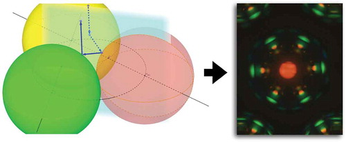
GRAPHICAL ABSTRACT
1. Introduction
Due to the helically periodic arrangement of the director, cholesteric liquid crystals (CLCs) have special optical properties [Citation1]. When the wavelength of the incident light is much smaller than the pitch of the CLC helix, the plane of linearly polarised light follows the helical twist and CLCs work as a polarisation waveguide. When the incident light wavelength is comparable to the pitch, CLCs work as photonic band gap materials and selective reflection of elliptically polarised light with the same handedness as the helix happens around a central wavelength
(Bragg’s law). Here, is the average refractive index of the cholesteric, p is the helix pitch and
is the angle of incidence. For
we have normal incidence, along the helix, and the ellipticity of the reflected polarisation is 1, i.e. the cholesteric reflects circularly polarised light. The width of the reflection band, the band gap, is (measured in air)
, where
is the birefringence the cholesteric would have if the helix were unwound. If the pitch, p, is on the order of visible light wavelengths, the selective reflection gives these short-pitch CLCs striking iridescent colours.
While liquid crystals were studied in spherical shape very soon after their discovery [Citation2], with a number of seminal works published also in the 1970s–1990s [Citation3–Citation10], not least in connection to polymer-dispersed liquid crystals [Citation11], the success of liquid crystals in the flat panel display industry has for a quite long time set a paradigm in which liquid crystals are studied primarily in a flat sample geometry. This is today changing and curved geometries like droplets, cylinders or shells are now drawing more attention [Citation12,Citation13] (and references therein), due to the many interesting effects arising from confinement within one (droplet) or two (shell) self-closing surfaces. Among the issues that have attracted the largest attention is the topological defects that must appear at the surface or in the bulk of spherical samples of nematic and smectic liquid crystals [Citation12–Citation23]. While liquid crystal droplets must have at least one topological defect within the droplet, on the surface and/or in the bulk, shells (containing an immiscible isotropic droplet as core) must contain topological defects in case of planar alignment on at least one of their surfaces (inner and outer), while homeotropic shells (i.e. with radial director) are defect-free, the topologically required bulk defect being a ‘virtual’ defect residing in the isotropic core.
In this paper, we focus on shells of cholesteric liquid crystals with a helix pitch that is so short that the helix becomes the optic axis and that we see only the effects of selective reflection in polarising microscopy, not the regular birefringence effect of non-helical nematics or smectics. Specifically, we focus on planar-aligned shells, which means that the helix orientation is radial and thus defect-free. The director field must still exhibit topological defects, due to the planar alignment, but since the optical properties are dominated by the selective reflection from the short-pitch cholesteric helix we see little or no effect of these defects. While there may be some effect, such as a reduction in reflection intensity in the vicinity of the defects, the influence of the topological defects on the optical properties discussed in this paper is so small that it could not be detected experimentally.
We found that arrays of monodisperse short-pitch CLC droplets with planar alignment at the outer surface exhibit an intriguing capacity for photonic cross-communication, giving rise to colourful geometric patterns that depend sensitively on the CLC pitch, droplet arrangement and the illuminated area [Citation24,Citation25]. The phenomenon results from a combination of the omnidirectional selective reflection of CLC droplets – which thus act as spherically symmetric self-assembled photonic crystals – and total internal reflection (TIR) at the interface between the continuous phase (typically aqueous) and air. Since the location of the CLC selective reflection band, , can be varied continuously by changing the amount of chiral material in the CLC, the colours of the reflection pattern can be tuned at will. By using photosensitive materials, such tuning can even be accomplished dynamically, after droplet production by exposing them to UV light, as demonstrated by the Li [Citation26] and Katsonis [Citation27] groups. Recently we demonstrated that the most distinct pattern is achieved by using CLC shells rather than droplets, since the reflections are then localised mainly to the surface [Citation28]. The shell geometry also has the advantage that polymer stabilisation of the CLC works very well, making the spheres mechanically robust with minimum negative effect on the optical properties. Another possibility of ensuring robustness is to encapsulate a CLC droplet inside a transparent elastomer shell [Citation29,Citation30].
Since the reflection is selective not only in wavelength but also in polarisation, the communication patterns can be turned on or off by changing the handedness of the illuminating light. By combining CLCs with right- and left-handed helices in one and the same sample, it is even possible to hide only a fraction of the reflection pattern in this way [Citation27]. In an elegant study, the Kim group combined a temperature-responsive CLC droplet with a surrounding shell of polymer-stabilised CLC, the two CLCs having opposite handedness [Citation31]. This allowed them to induce a very rich set of communication patterns by changing, on the one hand, the light polarisation, turning on the droplet, shell, or both reflection patterns. On the other hand, they could change the temperature, thereby dynamically changing the pitch of the inner CLC and thereby its reflection colour.
The unusual optical properties of CLC sphere arrays could be the basis for many potential applications. We presented arguments for the use in security of CLC shell arrays, applying them as so-called Physical Unclonable Function (PUF) tags for authenticating objects and persons via their unique optical patterns [Citation28]. This potential is vast thanks to the many new communication channels that can be opened by combining shells with different CLC pitch in one and the same sample. The unclonability of the patterns can be further enhanced by utilising also the appearance in transmission, since the remarkable optical properties of CLC shells are not limited to reflection [Citation32]. The Park group has demonstrated numerous ways of applying CLC droplets and shells in sensing [Citation33–Citation35]. The Musevic and Uchida groups have demonstrated omnidirectional lasing from CLC droplets [Citation36] and shells [Citation37], respectively.
Despite this rich body of literature on the investigation of CLC sphere arrangements (the above selection is not exhaustive) many subtle features of the communication patterns remain unexplained. There are in fact many less prominent reflection spots that have not yet been analysed, and even among the spots which have received their fundamental explanation, questions such as the size of the spot and the internal colour variations to be expected have not been addressed. In this paper, we take up these loose ends, complementing experimental observations with numerical simulations. This allows us to provide quantitative details to the spot types discussed so far. In addition, we also identify a number of new spot types, giving a rudimentary analysis based on experimental details for some of them, and a complete explanation based on a three-dimensional beam path simulation for one of them. The latter turns out to involve communication between three shells before the beam is directed back to the observer.
2. Experimental
2.1. Materials
The cholesteric liquid crystal (CLC) mixtures were prepared by adding the chiral dopant (R)-811 (Merck, Germany) to the commercial nematic mixture RO-TN 615 (Roche, Switzerland). The cholesteric pitch in our study was tuned by changing the concentration of (R)-811 between 20 and 28 wt.%. In that range, we could obtain infrared to yellow-green light in normal incidence selective reflection (the pitch becomes shorter with increasing concentration of (R)-811). For ensuring planar alignment at interfaces in a shell, a mixture of water and glycerol (Sigma-Aldrich) was used for the inner and outer phases in 80/20 volume ratio. Additionally, in order to prevent collapsing of as well as coalescence between shells, we dissolved 10 wt.% of polyvinyl alcohol (PVA, g mol–1, 88–89% hydrolysed, Sigma-Aldrich) in the aqueous phases.
2.2. Shell production and characterisation
Shells were produced in nested glass capillary microfluidic devices following the basic scheme of Utada et al. [Citation38]. Cylindrical glass capillaries were tapered using a micropipette puller (P-100, Sutter instrument, USA), and we cut the orifice to a desired diameter using a microforge (MF-900, Narishige, Japan). One tapered cylindrical capillary was used as injection tube for the inner aqueous phase and the other tapered capillary was used as a collection tube. The two tapered cylindrical capillaries were inserted into a square capillary, having the inner side length matched to the outer diameter of the cylindrical capillaries (). The outer surface of the injection capillary and the inner surface of the collection capillary were treated using octadecyl trichlorosilane (Sigma-Aldrich) and 3-[methoxy (polyethyleneoxy) propyl] trimethoxysilane (90%, 6–9 PE units) (ABCR GmbH), respectively, to ensure hydrophobic and hydrophilic characteristics, respectively. The outer square capillary was left untreated.
Figure 1. (Colour online) (a) Schematic drawing of the nested capillary set-up used for producing the CLC shells. The CLC is the middle fluid; the inner and outer fluids are isotropic aqueous solutions. (b) Shell production process captured by high-speed video camera. Scale bar is 200 m.
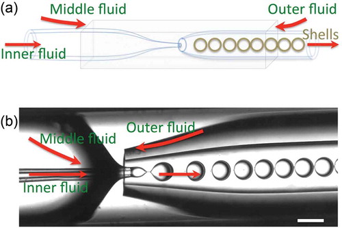
The shell production was done by pumping the three fluids with flow rate dynamically controlled by a four-channel microfluidic control unit (Fluigent, France), the CLC being the middle fluid, pumped from one side of the square capillary, meeting the outer fluid aqueous phase flowing in the opposite direction in the same square capillary, see . The inner droplet of each shell was injected by pumping the inner aqueous phase into the CLC flow using the injection capillary. After the complex flow breaks off due to the Rayleigh–Plateau instability, the resulting multiple emulsion is collected through the collection tube. The whole process was recorded using a high-speed camera (NX4-S3, Integrated Design Tools, Inc., USA), mounted on an inverted optical microscope (Eclipse TS100, Nikon, Japan). The microfluidic set-up was placed on a heating stage to keep the cholesteric mixture isotropic during the shell production. The shells were investigated in a polarising microscope (Olympus BX51, Japan), together with a digital camera (Olympus DP73, Japan).
3. Results and discussion
3.1. Polarising microscopy investigation
We studied a set of hexagonally close-packed identical shells (within experimental accuracy concerning shell diameter and thickness) in reflection polarising microscopy, monitoring the changes in communication pattern as a function of the opening of the field aperture, thus with varying fraction of the sample being illuminated, see . A low-magnification transmission polarising microscopy photograph of shells in the same hexagonal close-packed arrangement is shown in pane (a), where we have also identified with dashed rings the centres of the nearest neighbour (nn), next nearest neighbour (nnn), next next nearest neighbour (nnnn) and next next next nearest neighbour shells (nnnnn), with respect to the central shell, which is labelled A. For later convenience, we also introduce a specific labelling of the nn shells, giving them identifiers from B1 to B6.
Figure 2. (Colour online) (a) Polarising microscopy image in transmission of hexagonally closed-packed CLC shells illuminated from below by linearly polarised white light and observed through a crossed analyser. Each shell diameter is about 250 m. (b) Schematic illustrations explaining the origin of the most fundamental reflection spots i (normal incidence reflection), ii (TIR-mediated communication) and iii (direct communication). For an introductory explanation of these communication pathways, see papers [Citation24,Citation25]. (c–j) Reflection polarising microscopy textures of a hexagonally close-packed CLC shell arrangement, illuminated with linearly polarised white light from above, with a field aperture that gradually increases from c–d to i–j. The original micrographs are in the left column (c, e, g, i) and the corresponding digitally enhanced images are shown in the right column (d, f, h, j), boosting the visibility of very weak reflections.
![Figure 2. (Colour online) (a) Polarising microscopy image in transmission of hexagonally closed-packed CLC shells illuminated from below by linearly polarised white light and observed through a crossed analyser. Each shell diameter is about 250 m. (b) Schematic illustrations explaining the origin of the most fundamental reflection spots i (normal incidence reflection), ii (TIR-mediated communication) and iii (direct communication). For an introductory explanation of these communication pathways, see papers [Citation24,Citation25]. (c–j) Reflection polarising microscopy textures of a hexagonally close-packed CLC shell arrangement, illuminated with linearly polarised white light from above, with a field aperture that gradually increases from c–d to i–j. The original micrographs are in the left column (c, e, g, i) and the corresponding digitally enhanced images are shown in the right column (d, f, h, j), boosting the visibility of very weak reflections.](/cms/asset/1ac92531-be94-4555-9ef5-b86deaa8bda2/tlct_a_1363916_f0002_c.jpg)
The photographs in the left column of the subsequent rows are the original camera images as the field aperture is opened stepwise, whereas the right column contains the same photographs digitally enhanced to reveal also very weak communication spots. This enhancement also makes it easy to see the boundaries of the illuminated area, which is essentially the central shell (A) in panes c–d, covering more and more of the nn shells from e–f to g–h, until in i–j almost the whole imaged area is illuminated. As a guide for the eye the estimated shell boundaries are also indicated in the right column. When imaging the shells in reflection, with a focus setting that maximises spot sharpness, the shells appear somewhat smaller than they are.
In the left column we have highlighted representative examples of the three most important reflection spots, which were all given their basic explanations in [Citation24]. We show simple schematics of the corresponding reflection paths in pane (b). Spot i corresponds to direct reflection of the incident light back to the camera. This normal incidence reflection involves no communication between spheres and the colour reflects the pitch of the CLC helix, since . Spots ii and iii correspond to communication between adjacent shells, direct (spot iii) and via a TIR event at the continuous phase surface (spot ii). In pane (c) all spots arise from illumination of the A shell. In pane (e), in contrast, the field aperture has been sufficiently opened to allow direct communication from the nn shells to A, and we thus see the corresponding spots
appearing in the A shell. In pane (g) the further opened field diaphragm allows also TIR-mediated communication from the nn shells to the central shell, and spots
are now recognised. In pane (i), we highlight the direct and TIR-mediated communication between nnn shells, the spots labelled
and
, respectively.
The digital image enhancement applied to the images in the right column allow us to recognise several new types of communication spots, all highlighted and labelled in pane (d). The origin of spots of type iv will be analysed in full below, supported by simulations in Section 3.2.6, whereas the spots labelled with Greek letters from to
will only be briefly discussed in terms of the empirical observations in Section 3.1.3, leaving their full analysis to a future study.
3.1.1. Empirical conclusions concerning spots of type ii and ii′
While spots of types i, ii and iii have been extensively discussed in previous works, here we emphasise one aspect of spots of the TIR-mediated spots of type ii and that has not yet been analysed. This is the rainbow-like colour variation in the radial direction, best observed in ,i). Closer to the centre, the ii and
spots are orange, whereas they approach green towards the perimeter. This cannot be explained using the basic analysis presented in [Citation24], but using simulations of the reflection pattern, and considering the spread in incidence angle that is due to the non-zero cone angle of the microscope, as well as the possibility of reflections below the shell surface, we will be able to explain these features in Section 3.2.4.
3.1.2. Empirical conclusions concerning spots of type iv
We note in ) that the maximum number of type iv spots per shell is 12, seen in shell A when the illuminated area extends roughly one shell radius into the nn shells. Comparing with pane (d), where only the A shell is fully illuminated, and shells B6, B1 and B2 are partially illuminated, we see that no type iv spot is detectable in shell A whereas all B shells show at least two type iv spots each. This immediately tells us that the light of type iv spots originates from a different shell from that in which the spot is seen: the light hits shell A but the spots appear in the surrounding shells. However, if this were a regular two-shell communication, as for spots of type ii and iii, all type iv spots in all B shells should be present already in pane (d), since the A shell is fully illuminated. With some exceptions due to the slight asymmetry in illumination and varying distance between shells, only every second type iv spot is seen in the B shells of pane (d), as compared to pane (j) where each B shell shows four spots of type iv.
Specifically, each type iv spot furthest away from the A shell is visible in pane (d). (Note that these spots fall outside the image frame of for shells B3, B4, B6 and B1.) In order for the second type iv spot to become visible in each shell Bx, the illumination must reach the adjacent shell , as in panes (f) and (h). As the B shells become increasingly illuminated, the type iv spots eventually appear also in the A shell in pane (h).
This sequence of appearance of the type iv spots upon opening of the field aperture suggests that these spots arise from communication between three shells, e.g. from shell A to shell B4 to shell B5 for generating the encircled type iv spot in pane (d). Moreover, the blue colour of the spot, indicating a shorter wavelength than the direct communication type iii spots shows that the reflection angle must be greater than 45°, thus initially directed downwards below the horizontal plane. This more complex reflection path will be corroborated by simulations below, allowing us to fully visualise it.
3.1.3. Empirical conclusions concerning spots of type  to
to
A complete elucidation of all spots is beyond the scope of this paper, but we take the opportunity to identify six additional types of very weak spot, noting a few empirical observations that allow us to at least make some preliminary conclusions about their origin. We point out, however, that their complete explanation may require to take even more issues into account than what we are considering here, for instance lensing effects due to the curvature of the shells and the possibility of light entering also into the shell to varying extent, as well as non-selective reflections at the interfaces between different media. Upon large-area illumination (panes (h) and (j)), even more spots appear, hence even the identification in ) is not exhaustive.
Spots and
both appear in the central A shell while this shell is the only one illuminated, hence the beam paths of these spots must originate in the shell in which the spots are seen. However, they also show the hexagonal symmetry of the adjacent B shells (for the case of spots
, this symmetry applies to pairs of spots), showing that the paths must also involve the neighbour shells. In other words, it appears that the light is reflected by the A shell, reflected onto nn shells, which then reflect the light back to the A shell, which then directs the light back to the observer. The colour of both spots is red, suggesting that all reflections occur at small incidence angle.
We also note that straight lines can be drawn from the centre of shell A to every spot (orange) in an adjacent B shell, and these lines (drawn dotted blue in pane (d)) then pass through
spots, possibly indicating that they involve a common beam path. Likewise, every
spot in the A shell is correlated with a corresponding
spot in a B shell via a straight line from the centre of shell A, suggesting that this spot combination may constitute another joint communication path. In the direct vicinity of the
spots (which appear somewhat more orange than the
and
spots) we find green-coloured spots labelled
. In shell B2 these appear symmetrically on both sides of the
spots, whereas in the other shells only one
spot can be seen per
spot. The symmetry may suggest that these spots, apparently corresponding to higher incidence angle as revealed by their green colour, are generated by reflections between more than two shells. The same can be said for the nn shell spots labelled
, which appear to have no corresponding spot in the A shell.
3.2. Simulations of beam paths
3.2.1. Preliminary observations
The following aspects (listed in the order from source properties to the final image) may influence the perceived colours and were considered in the analysis:
Incident illumination: In the experiments the shells were illuminated by linearly polarised white light from an ordinary thermal light source. The axis of the illumination cone is perpendicular to the observation plane. We denote the angle of incidence with respect to the vertical direction in the lab plane by
Bragg reflection: All discussed light rays have undergone at least one Bragg reflection from a helix with
Bragg bandwidth: In the simulations, we varied the bandwidth of Bragg reflection (see Section 1) between
Shell thickness: The shells have an outer radius R and an inner radius
Imaging aperture: The imaging aperture of the microscope limits the range of angles
Colour representation: The emerging spectrum results from a convolution of the above-mentioned effects. Since the spectrum is not recorded by a spectral analyser but by a CCD camera, mapping a picture in RGB representation with device-dependent spectral response of the three colour filtering pixels, one has to be somewhat cautious about the interpretation of pictures like those shown in . In particular, this refers to the far red part of the spectrum where CCD cameras are practically insensitive to wavelength differences. Further issues, such as processing of the colour code at computer screens and/or print media are not further considered here. A rather simple colour model is used for the simulations, i.e. the colours shown in the simulation images below should only be considered a simple clue to the actual spectral distribution. The calculated wavelengths from the simulation should however have a reliability
The shells are assumed to be in contact with each other and to arrange in planar close packing configuration. We analyse only those reflections in that are marked as type i, ii, iii and iv, all originating from light above the A shell. Spots and
have identical origin to their unprimed versions, but they are due to illumination above one of the B-shells. Ignoring the weak
and
spots, the only reflection seen in A when no neighbour shells are illuminated (,d)) is of type i.
In the following, we assume that the maximum magnitude possible for incident angle is the same as the magnitude of the output angle
. For a first understanding of type
reflections, it is sufficient to consider a two-dimensional simulation in a plane containing the surface normal and the connection line of shell A and one is its nearest neighbours. Type iv requires a full three-dimensional simulation.
3.2.2. Technical details of the simulations
In the simulations, carried out with the software Geogebra, incident white light rays, represented by black arrows in the following figures, are scanned over the surface at a fixed angle of incidence in the range
set by the numerical aperture of the objective and the refractive index
of the embedding liquid medium. Only those ray paths are traced that match certain criteria. One of them is that angle
of the exit beam with respect to the normal of the surface should also be restricted to the range
. The definition of both angles can be gathered from .
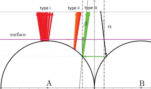
Figure 3. (Colour online) Ray path simulations for type i, ii and iii with expected colours emerging from the surface. The angle of incidence is the angle with which the illuminating rays impinge on the continuous phase surface, with respect to the vertical surface normal, and the angle
is the corresponding angle of the rays that are reflected back to the microscope objective, defined with respect to the same vertical direction. One incident ray, corresponding to green direct communication of type iii, is drawn as a black arrow and several other possible reflections, corresponding to type i and type ii spots, are also shown. The Geogebra simulation can be accessed by the weblink https://ggbm.at/NceyNemH.
At each Bragg reflection the wavelengths of the rays coming in and going out are compared. If the magnitude of the wavelength difference is larger than the Bragg reflection bandwidth, the ray paths are excluded. As colour model, we use HSV (Hue, Saturation, Value)-representation with a hue value linearly decreasing from 0.8 at 400 nm to 0 at 640 nm and 0 for wavelengths between 640 nm and 700 nm. All other rays are excluded.
3.2.3. Spots of type i: direct back reflection
Typical ray paths of type i back reflection is shown in . The wavelength spread of this central spot does not depend on the reflection radius r at all, but varies somewhat because the non-zero Bragg bandwidth permits rays within the cone angle to contribute to reflection. Even if one takes
to be equal to the maximum aperture angle of 9° of the objective, then the wavelength still varies only between
nm and
nm taking into account a small bandwidth of
nm. As discussed, the CCD camera represents all these colours uniformly by the same red colour. Assuming the observation plane to be at the surface plane, one obtains from ,j) for the ratio of maximum extension of the central spot relative to the radius of the shells the value
. This agrees well with the value
that can be found in the simulation for a limitation of the input/output angle of
(). The value corresponds exactly to the maximum angle that is possible in the medium for the given numerical aperture
of the objective and an average refractive index of 1.5. Therefore, this limit is used in all further simulations.
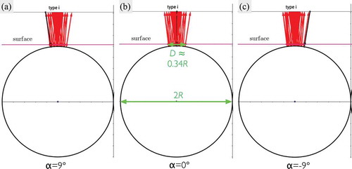
Figure 4. (Colour online) Ray path simulations for a type i spot with the expected colour emerging from the surface. The angle of incidence is varied from
(black arrow in a) to
(black arrow in c) with the reflected beams for all variations plotted simultaneously in all three panes. Measuring the diameter of the simulated spot in pane b (
) we find it to be about
, where R is the outer radius of the shell, which matches the experimental data from quite well. The Geogebra simulation can be accessed by the weblink https://ggbm.at/NceyNemH.
3.2.4. Spots of type ii and ii′: communication between two neighbours mediated by total internal reflection
As explained in [Citation24], back reflection can also be mediated by TIR and this is what gives rise to spots ii and in . We will now explain the slightly rainbow-coloured character of these spots as well as their non-negligible radial extension. Two possible approaches are shown in , taking the case of
spots, i.e. the light hits a B shell and is reflected onto the A shell via TIR between the shells. The left column (a–c) assumes reflections only at the outer surface, but the incidence angle may vary as much as allowed by the opening cone of the microscope. This can reproduce the radial extension (the reflected spot in (a) is the closest to the shell centre, that in (c) is the closest to the perimeter), and it also reproduces a colour variation, but it is in fact in the wrong direction: the spot the closest to the centre appears at shorter wavelength, that closer to the perimeter has a longer wavelength. As discussed in Section 3.1.1, the microscopy data reveals the exact opposite colour variation.
Figure 5. (Colour online) Ray path simulations for a type spot with the expected colour emerging from the surface. The left column assumes only surface reflection, but with incidence angle varying within the range allowed by the microscope illumination cone angle. While this reproduces the extension in space of the spot, it gives the wrong sequence of colours. The right column adds the possibility of below-surface reflection, and in this case the colour sequence as well as the extension in space are correct. Angle of incidence:
; Numerical aperture:
; Bragg reflection bandwidth:
; Radius of reflection surface:
; Wavelength for reflection of type ii:
. The Geogebra simulation can be accessed by the weblink https://ggbm.at/NceyNemH.
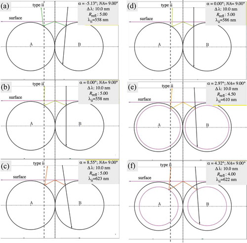
To explain the rainbow-like character, with the right order of colour, we need to allow for varying incidence angle as well as reflections slightly below the surface, see –f). In this way we achieve TIR-reflection spots of type that are not only extended in the radial direction, but they are also red-shifted towards the centre and blue-shifted towards the shell perimeter. This perfectly matches the observed microscopy textures in ,i), hence we believe this is the explanation for the character of these spots.
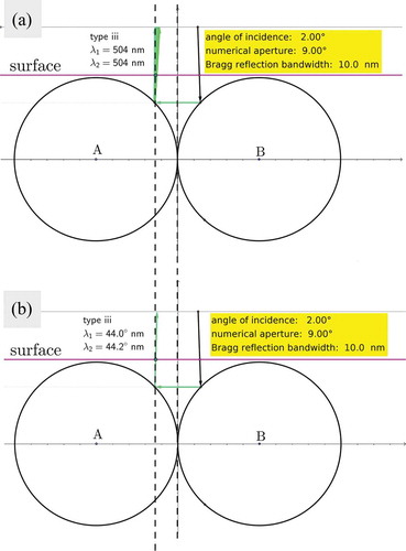
3.2.5. Spots of type iii and iii′: direct communication between two neighbours
Two representative ray paths of a type reflection are shown in , for two values of
. Following a greater set of simulations, we find that, depending on the angle of incidence, the colour of this spot type varies from blue (
nm at
) to green (
nm at
). The closer the rays are towards the centre of shell A, the shorter is their wavelength. Overall, the spot merged from contributions of the whole range of
appears bluish-green, but somewhat more bluish towards the centre of shell A. The calculated relative width of the reflection is
as compared to the measured width
. If the angle of incidence is fixed and the reflection radius r is varied, the colour practically does not vary, but covers a larger area on the observation surface.
Figure 6. (Colour online) Ray path simulations for a type spot with the expected colour emerging from the surface. Two values of the incidence angle
are shown, both within the opening angle of the microscope objective. The Geogebra simulation can be accessed by the weblink https://ggbm.at/NceyNemH.
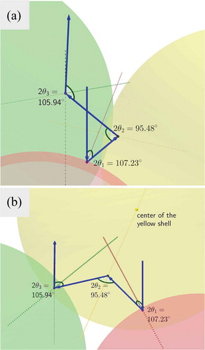
3.2.6. Spots of type iv: three-shell communication
The blue-coloured reflections of type iv always appear in pairs in between the reflections of type (see ). We propose that they are due to three-shell communication paths as supported by a three-dimensional Geogebra simulation (). In this particular simulation, the angle between the light path and the local axis of the cholesteric helix at each point of reflection varies between 48° and 54° which yields a relevant reflection band
. These data fit well with the observations seen in , hence they further substantiate the statement that type iv is the first example of a positively identified multiple-shell communication.
Figure 7. (Colour online) Three-shell communication responsible for blue reflections of type iv, viewed from two different angles. The central shell A is shown in red colour and two nearest neighbour B shells are shown in yellow and green, respectively. The angle of incidence is fixed at and for the depicted path
. The angles of reflection (Bragg angles) within the path vary between 48° and 54°, corresponding to wavelengths
, i.e. in the blue-violet range, requiring a large but reasonable bandwidth
. The Geogebra simulation can be accessed by the weblink https://www.geogebra.org/m/cEsDHWfH.
4. Conclusions
We have identified a much greater number of photonic communication spots in short-pitch cholesteric shells than were previously reported, and we have presented a detailed analysis, supported by computer simulations, of the four most prominent spots. One of these represents the direct back reflection, occurring as a single spot at the centre of every illuminated shell. The diameter of this spot (assuming complete shell illumination) depends on the shell diameter, the cone angle of the microscope used for observation, and the bandwidth of selective reflection, which in turn depends on the pitch of the cholesteric helix and the birefringence. For typical values, matching the systems experimentally investigated in this work, we find that the diameter of this central spot is slightly below 20% of the shell diameter. We explain the rainbow-like spatial colour variations that are often found in the type ii TIR-mediated reflection spots as a combined result of the non-zero spread of incidence angles and imaging angles
and the occurrence of sub-surface reflections, at some small distance into the shell. We analyse one previously unreported spot in full detail, concluding that this arises from three-shell communication, where for instance a central shell A is illuminated such that light is sent slightly downwards to an adjacent B shell, at an angle that leads to a subsequent reflection in its B shell neighbour, which then reflects the light back up to the observer. Due to the large angles between the cholesteric helix and light paths in this communication mode, the wavelength of this mode is short and the spots appear blue for a cholesteric that reflects red at normal incidence.
Acknowledgments
Financial support from the European Research Council under the European Union’s Seventh Framework Programme (FP/2007-2013)/ERC Grant Agreement n.648763 (consolidator project INTERACT), from the University of Luxembourg (project UNIQUE), and from the Slovenian Research Agency (ARRS) in the framework of the research programme P1-0192 is gratefully acknowledged. J.N. acknowledges support from the Fonds National de la Recherche (FNR, Ph.D. grant ULISCO, code 6992111).
Disclosure statement
No potential conflict of interest was reported by the authors.
Additional information
Funding
References
- Castles F, Morris S. Structure and optical properties of chiral nematic liquid crystals. In: Goodby JW, Collings PJ, Kato T, et al., editors. Handbook of liquid crystals. Vol. 3. Weinheim: Wiley-VCH; 2014. p. 493–520.
- Sluckin TJ, Dunmur DA, Stegemeyer H. Crystals that flow: classic papers from the history of liquid crystals. London: Taylor and Francis; 2004.
- Bouligand Y, Kléman M. Paires de disinclinaisons hélicoïdales dans les cholestériques [Helicoidal disclination pairs in cholesterics]. J Phys (Paris). 1970;31(11–12):1041–1054.
- Bouligand Y. Recherches sur les textures des états mésomorphes. 6—dislocations coins et signification des cloisons de grandjean-cano dans les cholestériques [Research on textures of the mesomorphic states. 6-edge disclinations and meaning of Grandjean-Cano walls in cholesterics]. J Phys (Paris). 1974;35(12):959–981.
- Kurik M, Lavrentovich O. Negative-positive monopole transitions in cholesteric liquid-crystals. JETP Lett. 1982;35(9):444–447.
- Volovik G, Lavrentovich O. Topological dynamics of defects: boojums in nematic drops. Zh Eksp Teor Fiz. 1983;85(6):1997–2010.
- Bouligand Y, Livolant F. The organization of cholesteric spherulites. J Phys (Paris). 1984;45(12):1899–1923.
- Lavrentovich O. Topological defects in dispersed words and worlds around liquid crystals, or liquid crystal drops. Liq Cryst. 1998;24(1):117–126.
- Xu F, Kitzerow H-S, Crooker P. Director configurations of nematic-liquid-crystal droplets: negative dielectric anisotropy and parallel surface anchoring. Phys Rev E. 1994;49(4):3061–3068.
- Xu F, Crooker P. Chiral nematic droplets with parallel surface anchoring. Phys Rev E. 1997;56(6):6853–6860.
- Drzaic PS. Liquid crystal dispersions. Singapore: World Scientific; 1995.
- Lopez-Leon T, Fernandez-Nieves A. Drops and shells of liquid crystal. Colloid Polym Sci. 2011;289(4):345–359.
- Urbanski M, Reyes CG, Noh J, et al. Liquid crystals in micron-scale droplets, shells and fibers. J Phys Condens Matter. 2017;29(13):133003.
- Nelson DR. Toward a tetravalent chemistry of colloids. Nano Lett. 2002;2(10):1125–1129.
- Lopez-Leon T, Koning V, Devaiah KBS, et al. Frustrated nematic order in spherical geometries. Nat Phys. 2011;7:391–394.
- Fernández-Nieves A, Vitelli V, Utada A, et al. Novel defect structures in nematic liquid crystal shells. Phys Rev Lett. 2007;99(15):157801.
- Skačej G, Zannoni C. Controlling surface defect valence in colloids. Phys Rev Lett. 2008;100(19):197802.
- Kralj S, Rosso R, Virga EG. Curvature control of valence on nematic shells. Soft Matter. 2011;7(2):670–683.
- Liang H-L, Zentel R, Rudquist P, et al. Towards tunable defect arrangements in smectic liquid crystal shells utilizing the nematic-smectic transition in hybrid-aligned geometries. Soft Matter. 2012;8(20):5443–5450.
- Liang H, Noh J, Zentel R, et al. Tuning the defect configurations in nematic and smectic liquid crystalline shells. Philos Transact A Math Phys Eng Sci. 2013;371(1988):20120258.
- Liang H-L, Schymura S, Rudquist P, et al. Nematic-smectic transition under confinement in liquid crystalline colloidal shells. Phys Rev Lett. 2011;106(24):247801.
- Noh J, Reguengo de Sousa K, Lagerwall JPF. Influence of interface stabilisers and surrounding aqueous phases on nematic liquid crystal shells. Soft Matter. 2016;12(2):367–372.
- Aguirre L, de Oliveira A, Seč D, et al. Sensing surface morphology of biofibers by decorating spider silk and cellulosic filaments with nematic microdroplets. Proc Natl Acad Sci U S A. 2016;113(5):1174–1179.
- Noh J, Liang H-L, Drevensek-Olenik I, et al. Tuneable multicoloured patterns from photonic cross communication between cholesteric liquid crystal droplets. J Mater Chem C. 2014;2(5):806–810.
- Noh J, Drevensek-Olenik I, Yamamoto J, et al. Dynamic and complex optical patterns from colloids of cholesteric liquid crystal droplets. In: Chien LC, Coles HJ, Kikuchi H, et al., editors. Proceedings of SPIE, emerging liquid crystal technologies X. San Francisco (CA): SPIE; 2015 Feb 9–13. p. X:93840T.
- Fan J, Li Y, Bisoyi H, et al. Light-directing omnidirectional circularly polarized reflection from liquid-crystal droplets. Angew Chem (Int Ed). 2015;54(7):2160–2164.
- Asshoff S, Sukas S, Yamaguchi T, et al. Superstructures of chiral nematic microspheres as all-optical switchable distributors of light. Sci Rep. 2015;5:14183.
- Geng Y, Noh J, Drevensek-Olenik I, et al. High-fidelity spherical cholesteric liquid crystal bragg reflectors generating unclonable patterns for secure authentication. Sci Rep. 2016;6:26840.
- Lee S, Kim B, Kim S, et al. Robust microfluidic encapsulation of cholesteric liquid crystals toward photonic ink capsules. Adv Mater. 2015;27(4):627–633.
- Lee S, Kim S, Won J, et al. Reconfigurable photonic capsules containing cholesteric liquid crystals with planar alignment. Angew Chem (Int Ed). 2015;54:15266–15270.
- Lee S, Seo H, Kim Y, et al. Structural color palettes of core-shell photonic ink capsules containing cholesteric liquid crystals. Adv Mater. 2017;29(23):1606894.
- Geng Y, Noh J, Lagerwall JPF. Transmission polarized optical microscopy of short-pitch cholesteric liquid crystal shells. In: Chien LC, Broer DJ, Kikuchi H, et al., editors. Proceedings of SPIE, emerging liquid crystal technologies XI. San Francisco (CA): SPIE; 2016 Feb 15–19. p. XI:97690U.
- Noh K, Park S. Smart molecular-spring photonic droplets. Mater Horizons. 2017;1(4):633–640.
- Jang J-H, Park S-Y. pH-responsive cholesteric liquid crystal double emulsion droplets prepared by microfluidics. Sens Actuat B Chem. 2017;241:636–643.
- Lee H, Munir S, Park S. Cholesteric liquid crystal droplets for biosensors. ACS Appl Mater Interfaces. 2016;8(39):26407–26417.
- Humar M, Muševič I. 3D microlasers from self-assembled cholesteric liquid-crystal microdroplets. Opt Express. 2010;18(26):26995–27003.
- Uchida Y, Takanishi Y, Yamamoto J. Controlled fabrication and photonic structure of cholesteric liquid crystalline shells. Adv Mater. 2013;25(23):3234–3237.
- Utada A, Lorenceau E, Link DR, et al. Monodisperse double emulsions generated from a microcapillary device. Science. 2005;308(5721):537–541.