
 ?Mathematical formulae have been encoded as MathML and are displayed in this HTML version using MathJax in order to improve their display. Uncheck the box to turn MathJax off. This feature requires Javascript. Click on a formula to zoom.
ABSTRACT
In a planar dielectric waveguide, weak confinement of a propagating mode in a high index core leads to a measurable evanescent interaction with the cladding. In this work, we study the effect of a reorientable anisotropic cladding on the behaviour of Transverse Electric (TE) and Transverse Magnetic (TM) mode polarisations using a liquid crystal (LC)-clad waveguide architecture. The polarised evanescent field of a guided mode interacts with a voltage-tunable birefringent LC cladding to deflect an out-coupled beam. Experimental measurements are coupled with a theoretical framework and show good consistency with simulation results. We isolate the effect of mode confinement by changing the thickness of the high index core. Interactions between the LC index ellipsoid and the mode polarisation are probed by changing the initial alignment of the LC. Finally, we examine the difference in deflection between TE and TM modes, which incorporates both a change in mode confinement and a difference in LC index components.
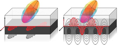
Graphical abstract
I. Introduction
The development of non-mechanical beam steering (NMBS) technologies is of great interest due to their potential to replace gimbal-based systems, which are comparatively bulky, power-hungry and slow. NMBS provides a means of rapidly addressing points in the field of regard, which is useful for applications such as free-space optical communication [Citation1] and Light Detection and Ranging (LIDAR) [Citation2–Citation4]. Diffractive NMBS has been successfully demonstrated by Polarisation Gratings (PGs) [Citation5–Citation7], Acousto-Optic Modulators (AOMs) [Citation8] and various types of Optical Phased Arrays (OPAs) [Citation9–Citation11]. However, these methods tend to be limited by the number of diffraction orders, power loss in side lobes and complicated design architectures. An elegant alternative to these approaches exploits refraction, where beam deflection occurs when light passes through a tunable LC-based prism. This approach is laser-agnostic and can be combined with other discrete steering devices, like PGs, to greatly expand the field of regard [Citation12]. The operating principle has been demonstrated by bulk transmission through a LC phase prism [Citation13,Citation14] and by utilising tunable LC prisms patterned in waveguides [Citation15–Citation17]. The latter method has demonstrated low SWaP (size, weight and power), high throughput (85%), rapid beam redirection (60 kHz) and continuous large-angle 2D steering (50° × 15°) [Citation12].
Planar waveguides with nematic LC serving as the core and cladding have been described in various geometries in literature [Citation18–Citation24], but have seen limited utility as beam steering devices due to losses in the LC [Citation25]. Scattering losses are dominant at shorter wavelengths [Citation26] and absorption losses oppress longer wavelengths [Citation27]. Using the LC as a cladding layer and targeting wavelength regimes with low scattering and absorption helps mitigate these losses, which has led to the commercial development of tunable LC waveguides in the short-wave IR (SWIR) [Citation12,Citation16]. Prototype devices have been developed in the near IR (NIR) [Citation28] and mid-wave IR (MWIR) [Citation17], but LC losses in these regimes can already be prohibitive. A comprehensive analysis of the interaction between the confined electric field and the LC can lead to more efficient design and is crucial to the continued development of this technology outside the SWIR.
Our work utilises a MWIR multi-layer planar dielectric waveguide as a refractive steerer () [Citation16,Citation17,Citation24], which consists of a high index core with a passive cladding and an active voltage-tunable nematic liquid crystal (LC) cladding ()). In this architecture, the guided mode is mainly confined in the core with the evanescent field extending into both cladding layers. A LC with positive dielectric anisotropy is aligned in the plane of the waveguide. When a sufficiently high voltage is applied across the LC, the force exerted on the molecules reorients the dipoles to align with the direction of the electric field and normal to the waveguide plane. The competition between the LC reorientation in the bulk and planar anchoring at the surface results in a distorted orientation profile that can be tuned by varying the strength of the applied voltage. Due to the birefringence of the LC, the distorted profile acts as an anisotropic graded index in the LC cladding. Altering the LC profile affects the cladding index seen by the guided mode, modifying the evanescent penetration of the mode into the LC and tuning the Goos-Hänchen shift at the core–LC interface [Citation29–Citation31]. This leads to a change in the effective mode index, , which is used to redirect the guided mode in a refractive manner.
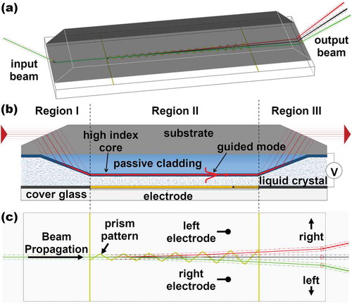
Figure 1. (Colour online) Overview of beamsteerer architecture and conventions. (a) 3D render of the device with a ray-tracing simulation of a beam coupled into the TM mode and undergoing refraction at the prism interfaces. Three overlaid beams highlight examples of left (red), right (green) and no-steering (black). (b) Side view of the multi-layered planar waveguide structure deposited on a faceted silicon substrate. A passive cladding isolates the mode from the high refractive index silicon and tapering in regions I and III allows for efficient coupling of a beam with the fundamental mode. The LC cladding is reoriented by applying a voltage to the upper electrodes. (c) Top view of the electrode pattern. Right and Left control electrodes accomplish left and right in-plane steering.
Transverse electric (TE) and transverse magnetic (TM) mode polarisations can be excited in a single-mode planar waveguide geometry. A result of the uniaxial LC cladding is that the orientation of the molecules on the surface can be parallel () or perpendicular (
) to the optical axis in the plane of the waveguide. Both of these operation styles affect the interaction between the guided mode and the active LC cladding. Utilising the LC cladding in the planar waveguide architecture, we present simulations and experimental results quantifying beam deflection with TE and TM guided modes and highlight the influence of core thickness and LC alignment on the direction and magnitude of beam steering. Based on fundamental principles of the light interaction with various LC orientations we find excellent agreement between simulation and experimental observations.
II. Methods
Liquid crystal-clad planar waveguides are fabricated as described in our previous work [Citation17]. The passive waveguide structures described in are grown on a p-type silicon substrate () to serve as a ground-plane electrode with facets polished on each end to permit prism coupling. The waveguide subcladding and core are vacuum-deposited soft chalcogenide glasses. The subcladding layer is grown with a tapered incoupling region [Citation32] and the core is rubbed with a nylon cloth to induce planar alignment of the LC [Citation33]. An indium tin oxide-coated cover glass serves as the upper electrode; it is lithographically patterned via standard lithographic techniques (), coated with polyimide (PI-2555) and rubbed for LC alignment. Two-part epoxy with
bead spacers is applied between the waveguide and cover glass to create a cavity that is filled with LC TL-213 (Merck) by capillary force in the isotropic state followed by slow cooling. The rubbing directions for the cover glass and chalcogenide surface are oriented to create a parallel aligned nematic liquid crystal device. Guided modes are excited in the waveguide using a narrow-bandwidth 40 mW mid-wave infrared (MWIR) quantum cascade laser (QCL) centred at
(ThorLabs LDMC20) and incident on the tapered in-coupling region. The laser power is not sufficient to induce noticeable nonlinear effects; thus, the position of the output beam is not affected by the incident light intensity.
Table 1. Materials and dimensions.
Three devices were fabricated. Two devices were made with a core thickness; one with the LC aligned planar perpendicular (
) and one planar parallel (
) to the optical axis. A third waveguide was made with a
core thickness and the LC aligned planar perpendicular (
). Each waveguide was designed to support one TE mode and one TM mode. These modes were excited while an electric field was applied to the left or right electrodes (), Region II & III) using a low noise square-wave voltage driver with amplitude and frequency control inputs, driven with a 1 kHz wave with amplitude between 0 and 130 Vrms. The out-coupled beam was directed at a target placed a fixed distance from the device and imaged with a MWIR camera (FLIR A6700sc). The deflection angle of the output beam was quantified by determining the centroid of the out-coupled spot on the target. This work examines the steady-state position of the beam after the motion was complete; switching dynamics are beyond the scope of this paper.
Simulations were carried out using COMSOL Multiphysics 5.4 with the Wave Optics Module.
III. Theory
The fundamental mode of the device is excited in Region I by prism coupling a beam through a tapered passive cladding () [Citation34–Citation36]. The increasing thickness of the lower cladding isolates the guided mode in the core (and from the substrate) which then propagates through Region II. The isotropic indices and layer thicknesses are chosen to force the evanescent field of the guided mode into the LC, which can be modulated by the LC orientation. We define the stroke of the device,
, as the modulation range of effective mode indices attainable with an applied voltage. This modulation occurs only under the boundaries of the driven electrode ()). At an electrode boundary, the guided mode refracts in the plane of the waveguide as it passes from one voltage-tuned effective index region to another. The zig-zag prism pattern in the electrode compounds small refractions to produce a significant deflection of the guided mode. In Region III, the presence of the high index substrate causes the guided mode to couple out as a
beam.
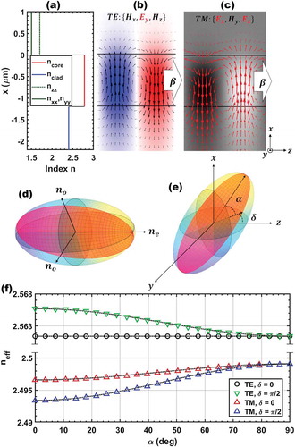
Region II is modelled in two dimensions by a three-layer waveguide structure with the values defined in and shown in ). The propagating mode is mainly confined in the isotropic high-index core with the evanescent field penetrating into the anisotropic upper cladding. The full E- and H-fields are shown in ,). To accurately represent the anisotropy of the cladding, the LC layer is described using a uniaxial index ellipsoid ()). The index tensor of LC in the material frame is
Figure 2. (Colour online) Tunable mode interaction with LC. (a) Index profile of lower cladding (), core (
) and anisotropic upper cladding (
,
,
) given the parameters in . (b) TE modes propagating in the waveguide structure showing the E-field oscillation in the y direction (red and blue) and the curl of the H-field (black arrows). (c) TM modes propagating in the waveguide structure showing the
and
components of the field (red arrows) and oscillation of the H-field in the y direction (black and white regions).
indicates the propagation direction of the guided mode. (d) LC index ellipsoid with ordinary and extraordinary axes
and
. (e) The index ellipsoid rotated about its centre by an azimuthal angle
in the plane of the waveguide and polar angle
out of the plane. (f) Simulated effective waveguide index for TE and TM modes with
(
) and
(
) alignment as a function of the out-of-plane tilt angle
. Dotted black lines show a
fit to the data, defined in Equation (7).
where and
are the ordinary and extraordinary indices, respectively. The ellipsoid is reoriented using the matrices
and
, which rotate the long axis around the x and y axes, respectively, to produce the index tensor in the waveguide frame ()).
rotates the index tensor in the plane of the waveguide with an angle
, which is experimentally dictated by the surface alignment direction.
reorients the tensor out of the plane of the waveguide with an angle
. This reorientation occurs experimentally when an external field is applied across the LC bulk. Applying these rotation matrices to the index ellipsoid results in the following symmetric tensor
which contains diagonal components
and coupling terms
In our present study we consider two in-plane angles: and
, which correspond to
and
alignment, respectively. The four configurations that we consider are (1) TE with
, (2) TM with
, (3) TE with
and (4) TM with
. The graded index that results from the Fréedericksz transition in the LC [Citation37–Citation39] is approximated as a homogeneous average value as sampled by the evanescent field of the guided mode and is, as a result, independent of the anchoring strength. Another consequence of the graded index is that, experimentally, the full range of LC orientation is not accessible due to anchoring at the aligning surface. The voltage dependence of index modulation is a complicated function and is not addressed in this work.
Table 2. Simulation results.
The effective waveguide index is determined by solving Maxwells Equations in the waveguide structure. The full stroke of the waveguide, , in each configuration is considered to be the tunable range of the effective index as
is rotated from
to
,
which are the theoretical limits for voltage tunability of the LC orientation.
For a given surface orientation (), the effective mode index scales with the voltage (
) by
which is shown in ). The black dotted curves show the fit. The deflected index is defined as
It follows that the ratio of the deflected index for any two configurations 1 and 2 is independent of and therefore equivalent to the stroke ratio
The magnitude of the deflected index is strongly dependent on the mode field volume in the LC, as this dictates how much of the guided mode penetrates into the LC index ellipsoid. A larger mode field volume in the LC increases the stroke of the waveguide under the condition that the guided mode is supported by the high-index core.
IV. Results and discussion
We first examined the effect of core thickness, , on the device stroke. It is expected that a thicker core results in less of the field penetrating into the LC, and thus reduces the stroke. Using COMSOL, we calculated TE and TM effective mode indices for the full waveguide structure in both orientations (
and
) and for two different core thicknesses (
and
). The complete results are summarised in .
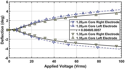
In-plane steering of TM modes was experimentally measured in two devices with core thicknesses of and
(). By applying Equation (9), we accurately predict the reduction of steering in the
device by scaling the
curve by the ratio of the simulated strokes:
.
Figure 3. (Colour online) Experimental results for in-plane steering of TM modes in devices with
(blue) and
(yellow) core thicknesses. Simulation data (black) are obtained by taking the ratio of the strokes simulated using COMSOL.
We then examined TM modes in both the and
orientation, which have non-zero field components in both the
and
direction. These components interact with the LC index ellipsoid, which dictates their propagation in the core. The index of the LC cladding,
, lies between
and
and is derived by taking the intersection of the field vector with the index ellipsoid. With
alignment ()),
interacts with
and
interacts with
.
Figure 4. (Colour online) Schematics of TM wave interactions with (a) planar parallel, (b), planar perpendicular and (c) homeotropic (normal to the y-z plane) alignment. (d) Calculated indices for the LC aligned (red),
(blue) and homeotropic (black) as a function of the normalised
component of the field. (e) Stroke of the LC as calculated from (d). (f) Experimental results showing in-plane steering with TM modes in
(red) and
(blue) devices with a
core thickness and the simulated stroke scaling (black).
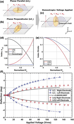
An applied field across the LC cladding reorients the index ellipsoid, which represents a change in the average orientation of the LC. If we assume that a high enough field realigns the LC perpendicular to the surface ()), interacts with
and
interacts with
.
The case of alignment is less complex. Since the
orientation of the ellipsoid is orthogonal to both field components,
and
both interact with
and effectively experience an isotropic index ()).
As a field is applied and the ellipsoid reorients, the case is the same as described by Equation (11), where interacts with
and
interacts with
()). A plot of Equations (10–12) and the resulting stroke for the two configurations are shown in and , respectively. A consequence of this geometry is that a non-zero
component reduces steering and there is an inherent crossover point where, when
, the
steering would be negative. By considering the waveguide cut-off condition, the latter case corresponds to radiating modes by implying that the effective index is lower than the cladding index.
The existence of a guided mode forces , where the effective index increases as a field is applied in both the
and
orientation. As a result, applying a voltage across a prism (left or right, )) causes the beam to deflect towards the driven electrode, which is observed experimentally (). Using , we predict the steering amplitude by scaling the high steering geometry,
, curve by the ratio of the simulated strokes:
. By applying this stroke reduction to the calculations shown in ), it follows that there is a
reduction in the steering of the
device due to the z-component of the field.
The E-field of the TE mode oscillates in the plane of the waveguide and therefore sees the LC as an isotropic index. In a device, the LC index is
with no field applied and remains constant as the index ellipsoid is rotated by an angle
towards a homeotropic (normal to the y-z plane) alignment. This situation leads to no steering of the device as indicated by zero stroke in . The
device, on the other hand, has an LC index of
with no field applied and
in the homeotropic case. This gives a tunable device that can theoretically experience the full range of LC index in contrast to the inherent limitations of the TM mode shown in ). This reorientation decreases the effective index of the waveguide. As the guided mode passes under the prism electrode pattern, it refracts away from the driven electrode, towards regions on the higher index. Practically, this translates to the TE mode deflecting left when the right electrode is driven and right when the left electrode is driven.
Antithetically, TM modes in a device have a LC index of
with no field applied that increases with reorientation. The guided mode, which refracts towards regions of a higher index, cause deflection to the right when the right electrode is driven and deflection to the left when the left electrode is driven. The difference between the modes is shown schematically in –) and –). We experimentally quantified the in-plane deflection angles ()), observing that TM modes steer to a larger extent than TE modes. These observations are consistent with simulation results, which show a negative steering ratio:
. The reduced steering seen in the TE mode seems counterintuitive from the arguments made above, but it is important to note that a direct comparison can only be made if the mode volume in the LC is equal. While we showed that a portion of the evanescent field from the TM mode in the LC is wasted, which does not occur in the TE mode, the observed enhancement is actually a result of the weaker mode confinement. The orientational geometry of the TM mode leads to a smaller modulation of the apparent LC index but a larger fraction of the power propagates in the LC layer, thereby amplifying the stroke.
Figure 5. (Colour online) Schematics of TE wave interactions with (a) planar parallel, (b), planar perpendicular and (c) homeotropic alignment. (d) Experimental results showing in-plane steering for TE (green) and TM (blue) modes in a device with a
core thickness. (e) The index stroke as a function of the relative power in the LC in TE and TM modes in core thicknessess varying from
to
.
represents the average relative power over the stroke,
represents low power (planar) alignment and
represents high power (homeotropic) alignment.
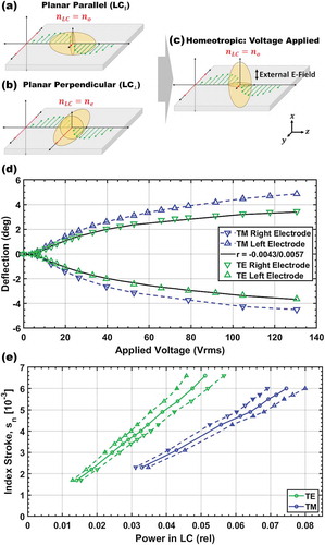
To more clearly demonstrate the difference between TE and TM mode deflection in LC-clad waveguides, it is important to look at the effective stroke as a function of the power in the LC. This can be calculated by the ratio of the field intensity in the LC to the total field intensity in the waveguide with varying core thickness. A plot of simulation results for index stroke vs the relative power in the LC as the core thickness varies from to
is shown in ). To achieve the same index stroke in the waveguide, much larger fields are required in the LC with TM modes. The greatest steering we experimentally observed was for TM modes in a waveguide with a
core, which requires more than
of the power in the LC. A waveguide with a
core, which supports a TE mode but no TM mode, would achieve the same stroke with
of the power in the LC.
We note that our treatment of the system neglects the distorted LC profile that results from an applied field and instead uses a step index approximation for the waveguide while showing consistency with experimental results. A case can be made that this is due to small fields in the LC () and the resulting diminutive change in the evanescent field penetration into the LC upon tuning. The amplitude of this change is apparent by comparing the tunability of the effective waveguide index to the change in LC index, which is 2 orders of magnitude larger. It is reasonable to assume that as more of the mode penetrates into the LC, the graded index plays a larger role.
V. Conclusion
An analysis of the steering magnitude of positive dielectric LC-clad waveguides with planar alignment was carried out using theory, simulation and experimental results. We first showed the effect of mode confinement by controlling the thickness of the waveguide core. Larger confinement in the core results in less of the field penetrating into the LC and thus a reduction in steering. Furthermore, we showed the effect of field components on steering by aligning the LC parallel and perpendicular to the TM beam propagation direction. The performance in these configurations demonstrates that multiple field components, having both and
for TM modes, in an uniaxial material limit the steering of the device, as one axis is always agnostic to distortion. Finally, we combined the first two cases to explore TE and TM mode steering. While TE mode steering more efficiently used the LC due to the singular component of the E-field, the higher confinement of the mode actually results in reduced steering compared with the TM mode. However, it is important to highlight that the TM modes result in inefficient steering due to unused (not tunable) fields in the LC that would still contribute to losses in the device.
Disclosure statement
No potential conflict of interest was reported by the authors.
Additional information
Funding
Related Research Data
References
- Killinger D. Free space optics for laser communication through the air. Opt Photonics News. 2002;13(10):36–42.
- Wallin S, Pettersson A, Ostmark H, et al. Laser-based standoff detection of explosives: a critical review. Anal Bioanal Chem. 2009;395(2):259–274.
- Svanberg S. Environmental and medical applications of photonic interactions. Phys Scr. 2004;T110:39–50.
- Chen H, Weng Y, Xu D, et al. Beam steering for virtual/augmented reality displays with a cycloidal diffractive waveplate. Opt Express. 2016;24(7):7287–7298.
- Kim J, Oh C, Escuti MJ, et al. Wide-angle nonmechanical beam steering using thin liquid crystal polarization gratings. In: Gonglewski JD, Carreras RA, Rhoadarmer TA, editors. Proc. SPIE 7093, Advanced Wavefront Control: Methods, Devices, and Applications VI. vol. 7093. San Diego, CA: International Society for Optics and Photonics; 2008. p. 709302.
- Kim J, Oh C, Serati S, et al. Wide-angle, nonmechanical beam steering with high throughput utilizing polarization gratings. Appl Opt. 2011;50(17):2636.
- Kim J, Miskiewicz MN, Serati S, et al. Nonmechanical laser beam steering based on polymer polarization gratings: design optimization and demonstration. J Lightwave Technol. 2015;33(10):2068–2077.
- Gesell LH, Feinleib RE, Lafuse JL, et al. Acousto-optic control of time delays for array beam steering. Proc SPIE 2155, Optoelectronic Signal Processing for Phased-Array Antennas IV, Los Angeles, CA. 1994;2155:194–204.
- Mcmanamon PF, Member S, Dorschner TA, et al. Optical phased array technology. Proc IEEE. 1996;84(2):268–298.
- Poulton CV, Byrd MJ, Timurdogan E, et al. Optical phased arrays for integrated beam steering. In: 2018 IEEE 15th International Conference on Group IV Photonics (GFP), Cancun, Mexico; 2018. p. 1–2.
- Niu Q, Wang C, Shi H, et al. Development status of optical phased array beam steering technology. In: Proc. SPIE 11052, Third International Conference on Photonics and Optical Engineering. SPIE-Intl Soc Optical Eng, Xi'an, China; 2019. p. 110521P.
- Ziemkiewicz M, Davis SR, Rommel SD, et al. Laser-based satellite communication systems stabilized by non-mechanical electro-optic scanners. In: Proc. SPIE 9828, Airborne Intelligence, Surveillance, Reconnaissance (ISR) Systems and Applications XIII. vol. 9828. Baltimore, Maryland: SPIE; 2016. p. 982808.
- Golovin AB, Shiyanovskii SV, Lavrentovich OD Gradient beam steering device based on a nematic cell with continuous ramp of the phase retardation. In: Proc. SPIE 5741, Emerging Liquid Crystal Technologies, San Jose, CA. vol. 5741; 2005. p. 146–153.
- Otón E, Pérez-Fernández J, López-Molina D, et al. Reliability of liquid crystals in space photonics. IEEE Photonics J. 2015;7:4.
- Sheridan JP, Giallorenzi TG. Electro-optically induced deflection in liquid-crystal waveguides. J Appl Phys. 1974;45(12):5160–5163.
- Davis S, Rommel S, Johnson S, et al. Electro-optic steering of a laser beam. SPIE Newsroom. 2011;13.
- Frantz JA, Myers JD, Bekele RY, et al. Chip-based nonmechanical beam steerer in the midwave infrared. J Opt Soc Am B. 2018;35(12):C29–C37.
- Lin H, Moroi DS, Palffy-Muhoray P. Wave propagation in liquid crystal slab waveguides. Mol Cryst Liq Cryst Sci Technol Sect A Mol Cryst Liq Cryst. 1992;223:241–249.
- Caño-García M, Elmogi A, Mattelin MA, et al. All-organic switching polarizer based on polymer waveguides and liquid crystals. Opt Express. 2018;26(8):9584–9594.
- Donisi D, Bellini B, Beccherelli R, et al. A switchable liquid-crystal optical channel waveguide on Silicon. IEEE J Quantum Electron. 2010;46(5):762–768.
- Green M, Menown JS, Yeoh C. Near surface relaxation time for liquid crystal clad optical waveguides. Appl Opt. 1991;30(3):278–280.
- Okamura Y, Kitatani K, Yamamoto S. Electroopic leaky anisotropic waveguides using nematic liquid crystal overlayers. J Lightwave Technol. 1984;LT-2(3):292–295.
- Chen BX, Li XT, Limura Y, et al. High-contrast channel waveguide switch with two sections of a nematic liquid crystal covering. Appl Opt. 1993;32(30):6018–6021.
- Davis SR, Farca G, Rommel SD, et al. Liquid crystal waveguides: new devices enabled by >1000 waves of optical phase control. In: Chien LC, editor. Proc. SPIE 7618, Emerging Liquid Crystal Technologies V. San Francisco; 2010. p. 76180E.
- Hu C, Whinnery JR, Hut C, et al. Losses of a nematic liquid-crystal optical waveguide*. J Opt Soc Am. 1974 Nov;64(11): 1424.
- Giallorenzi TG, Sheridan JP. Light scattering from nematic liquid crystal waveguides. J Appl Phys. 1975;46:1271–1282.
- Chen Y, Xianyu H, Sun J, et al. Low absorption liquid crystals for mid-wave infrared applications. Opt Express. 2011 May;19(11):10843–10848.
- Keller SD, Uyeno GP, Lynch T, et al. Emerging liquid crystal waveguide technology for low SWaP active short-wave infrared imagers. In: Proc. SPIE 9384, Emerging Liquid Crystal Technologies X; vol. 9384. San Francisco, CA: SPIE; 2015. p. 93840M.
- Goos VF, Hänchen H. Neumessung des Strahlwersetzungseffektes bei Totalreflexion. Ann Phys. 1949;6(5):251–252.
- Kogelnik H, Weber HP. Rays, stored energy, and power flow in dielectric waveguides*. J Opt Soc Am. 1974;64(2):174–185.
- Snyder AW, Love JD. Goos-Hänchen shift. Appl Opt. 1976;15(1):236–238.
- Myers JD, Frantz JA, Spillmann CM, et al. Refractive waveguide non-mechanical beam steering (NMBS) in the MWIR. Proceedings Volume 10539, Photonic Instrumentation Engineering V, San Francisco, CA; 2018;10539(February):105390A.
- Frantz JA, Myers JD, Spillmann CM, et al. Liquid crystal alignment on chalcogenide glass; 2018.
- Ulrich R. Theory of the prism-filn coupler by plane-wave analysis. J Opt Soc Am. 1970;60(10):1337–1350.
- Ulrich R. Optimum excitation of optical surface waves. J Opt Soc Am. 1971;61(11):1467–1477.
- Midwinter JE. Evanescent field coupling into a thin-film waveguide. IEEE J Quantum Electron. 1970;6(10):583–590.
- Motooka T, Fukuhara A, Suzuki K. Freedericksz transition and anchoring effects in the oblique configuration of a nematic liquid crystal. Appl Phys Lett. 1979;34(5):305–306.
- Fréedericksz V, Repiewa A. Theoretisches und Experimentelles zur Frage nach der Natur der anisotropen Flüssigkeiten. Zeitschrift für Physik. 1927;42(7):532–546.
- Fréedericksz V, Zolina V. Forces causing the orientation of an anisotropic liquid. Trans Faraday Soc. 1933;29(140):919–930.