
 ?Mathematical formulae have been encoded as MathML and are displayed in this HTML version using MathJax in order to improve their display. Uncheck the box to turn MathJax off. This feature requires Javascript. Click on a formula to zoom.
ABSTRACT
To improve the characteristics and quality of the photoalignment of liquid crystals has been a main goal of many relevant studies. We demonstrate in this work, following the general concept of composite materials, that the photoalignment of liquid crystal can substantially be improved when using alignment layers made from photoalignment composite materials. These composites contain at least one photoalignment material. The other components of the photoalignment composite material may or may be not photosensitive, as conventional polyimide materials, for instance.
We show that by a proper choice of the components, the properties of the photoalignment materials, made by photoalignment composites, can be tailored in a broad range, resulting in higher sensitivity, and thus shorter exposure time, uniform and smooth photoalignment topography (without domains and sandy structures) resulting in high image contrast. High-quality photo-patterning of the liquid crystal alignment is demonstrated in this work with a photoalignment composite material containing one of our photoalignment materials and a conventional polyamide alignment material.
Introduction
As well known, the liquid crystals consist of molecules possessing anisotropic molecular structure and, thus, anisotropic physical properties, such as optical (birefringence), electrical and magnetic anisotropy. To make use of these unique physical properties, the liquid crystals have to be aligned first along a preferred direction, either by external fields, such as optical, magnetic and/or electric, or by the interactions with a solid substrate surface, being non-treated or treated. The alignment of liquid crystal molecules, promoted by the surface substrate they are in contact with, has been in the focus of many scientists and engineers during the past several decades. The external fields align the liquid crystals by coupling between the applied field and the anisotropic liquid crystal physical properties. Similarly, the interactions between the liquid crystal and the solid substrates should have anisotropic character in order to align the liquid crystal, that is the contact surface of the solid substrate should have anisotropic physical properties, which enable it to impose a certain kind of alignment on the liquid crystal molecules, transmitted further to the liquid crystal bulk. Hence, the key issue in the alignment of liquid crystals by solid substrates is that their contact surface with the liquid crystal should possess anisotropic physical properties. Usually, for liquid crystal displays and devices, glass plates are used as confining substrates. These substrates are entirely or partially covered by ITO transparent conductive layer representing the electrodes. However, such glass substrates, with or without ITO, do not promote any uniform alignment on the liquid crystal in contact with the substrate surface. Usually, it’s promoting random planar or tilted alignment, and, at certain wetting conditions, the substrate surface may result in a vertical (homeotropic) alignment, as well [Citation1]. The substrate contact surface may adopt anisotropic physical properties either by direct treatment of the glass substrate surface, such as unidirectionally mechanical rubbing [Citation2–4], by oblique deposition of inorganic films, such as SiOx [Citation5], or by organic thin layers deposited onto the substrate surface and properly treated afterwords. These organic layers are usually different kinds of polymers, which are treated either by mechanical unidirectional rubbing or by exposure to Linear Polarised UV (LPUV) light to obtain anisotropic physical properties of the contact substrate surface. General description of the basics of photoalignment process of liquid crystals and appropriate photoalignment materials, and their structures are presented in the book of V. G. Chigrinov et al. [Citation6] and in the overview of O.Yaruschuk and Y. Reznikov [Citation7].
The mechanical rubbing process of polymer alignment layers is still dominating the industrial alignment technology for Liquid Crystal Displays (LCD). The rubbing alignment technology is a matured technology but has several disadvantages, such as generating of electrical charges, dust, and damages of TFT elements of the liquid crystal screens, for instance. This technology is also not appropriate for patterning of the liquid crystal alignment, which is a prerequisite for reducing or completely avoiding the viewing angle dependence of the liquid crystal displays and devices. On the other hand, a new technology, which is a non-contact technology, called photoalignment, was first reported in 1991 [Citation8] and other pioneering works in this field [Citation9–12]. A broad range of appropriate photoalignment material systems was presented by K Ichimura later in 2000 [Citation13]. The photoalignment technology was first industrially employed in 2009 by Sharp (UV2 Technology) in collaboration with ROLIC Ltd, Switzerland, and continues to attract the attention of scientists and engineers even today [Citation14].
The photoalignment technology has several advantages compared to rubbing alignment technology. It doesn’t generate mechanical defects, electrical charges, and dust. It is a non-contact alignment technology, which enables patterning of the liquid crystal alignment and it makes also possible to align liquid crystals on curved substrates, which otherwise is impossible to obtain by means of rubbing technology.
In the beginning of 2000, our Liquid Crystal Group at University of Gothenburg, Sweden, introduced two novel alignment concepts, one, for alignment and switching of the liquid crystals by Electrically Command Surfaces (ECS) and the other, for alignment and facilitating the switching of the liquid crystals, the so-called High Performance Alignment Layers (HiPAL) [Citation15,Citation16].
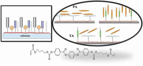
During the development of alignment materials according to these novel concepts, it was realised that the structural properties of the alignment polymer materials in a nanoscale are of vital importance for the alignment on the liquid crystal promoted by these materials. Therefore, we introduced another novel liquid crystal alignment concept, which we called as nano-structured alignment materials, in which structure is combined units with different functionality ( and ). These liquid crystal alignment materials are side-chain polymers, in which side groups are chosen to bring certain properties to the alignment layer, such as kind of alignment, planar, vertical, or tilted, strong or weak anchoring, ionic traps, photoalignment, etc. ( and ).
Figure 1. (Colour online) Schematic presentation of the structure of side-chains polymers and the attachments of their side-groups to the main-chain of the polymer for promoting planar (PA), vertical (VA) and tilted (TA) alignment of the liquid crystals, respectively, according to the nano-structured alignment materials concept [Citation16,Citation19–21].
![Figure 1. (Colour online) Schematic presentation of the structure of side-chains polymers and the attachments of their side-groups to the main-chain of the polymer for promoting planar (PA), vertical (VA) and tilted (TA) alignment of the liquid crystals, respectively, according to the nano-structured alignment materials concept [Citation16,Citation19–21].](/cms/asset/5e2b8f86-b3d1-4556-bc4f-f30b32b3bff2/tlct_a_1930211_f0001_oc.jpg)
Figure 2. (Colour online) Schematic presentation of the general structure of a side-chains polymer, for liquid crystal alignment according to the nano-structured alignment materials concept [Citation14–16,Citation19], containing side-chain groups with different functionality.
![Figure 2. (Colour online) Schematic presentation of the general structure of a side-chains polymer, for liquid crystal alignment according to the nano-structured alignment materials concept [Citation14–16,Citation19], containing side-chain groups with different functionality.](/cms/asset/500be621-f085-4b08-a6d3-04c97a7faa8f/tlct_a_1930211_f0002_oc.jpg)
As shown in , the alignment materials for planar alignment (PA) contain mesogenic side-chain groups attached to the robust main-chain (Maleimide-N-Vinillactam) laterally (side-on), whereas the alignment materials for vertical alignment (VA) contain mesogenic side-chain groups attached longitudinally (side-end) to the main-chain. The types of the side groups are selected properly to ensure efficient alignment effect. The alignment layers for promoting tilted alignment of the liquid crystals (TA) contain both kinds of side-chain groups, with side-on and side-end attachment, respectively.
Below is schematically presented the concept of nano-structured alignment material for LCDs (for more information www.highvistec.com). Based on this concept, we designed and synthesised photoalignment polymer materials containing in its structure photo-sensitive side group, such as
benzophenone, for instance. Their alignment properties were tailored by a proper choice of the side-chain groups and of the polymer backbone, representing the material the alignment layer is made of.
We found also that it is possible to tailor the properties of the photoalignment layers when they are made from a proper photoalignment composite materials. Such approach was previously reported also by other researchers [Citation17,Citation18].
In this work, we report some of the results obtained in our study on the alignment of liquid crystal using alignment layers made of photosensitive composites containing different combinations of the following components:
liquid crystal monomer
photoreactive liquid crystal monomer
photoalignment material
conventional alignment material.
Several examples of nematic liquid crystals aligned by photoalignment layers made from such photosensitive composites are presented and discussed in this work.
Experimental
Within a project, we developed in close collaboration with Nissan Chemical Industries, Japan, novel photoalignment materials, based on our concept of nano-structured alignment layers [Citation16,Citation19–21]. In the process of developing the nano-structured photoalignment materials, we found that some of the characteristics of these materials can be improved by adding some of the above-mentioned components as well as to convert ordinary (conventional) alignment materials to photo-alignment materials.
Photoalignment by photoreactive liquid crystal monomer
The anchoring of the liquid crystals on a solid substrate surface is very delicate balance of several important interactions such as Van der Vaals, dipole-dipole, physicochemical, sterical, etc. It is well known that only a substrate possessing anisotropic surface physical properties is capable to promote a certain type of alignment of the liquid crystal corresponding to the character of the anisotropy of solid surface physical properties.
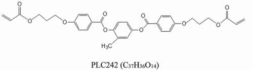
In our work, we studied the alignment properties of organic materials, such as polymers, formed or deposited on a solid substrate surface, after illumination with linear polarised UV light. This illumination generates anisotropy of the physical properties of the alignment layer, which in our case is made from photoalignment composite material. To increase the degree of the surface anisotropy we include in our photoalignment materials a photoreactive material, which is a liquid crystalline. First, we tested a photo polymerisable thermotropic liquid crystal material Paliocolor LC242 (BASF) [Citation22]) which has a nematic phase in the interval 30°C N 125°C on cooling and 63–70°C N 125°C on heating (see ). Paliocolor LC242 (or PLC242) was designed and synthesised for production of optical compensating films. It should be oriented first, as in the case of the conventional nematic liquid crystals, and then photopolymerised by illumination with UV light. LC242 is created only to photopolymerise, not to provide any uniform orientation during the photopolymerisation process. Importantly, we found that PLC242 could be photoaligned as well, when illuminated with linear polarised UV light.
Figure 3. Molecular structure of the liquid crystal diacrylate Paliocolor LC242 (BASF), used in this work. The nematic phase of PLC242 persists between ~70°C and 120°C.
The liquid crystal alignment layer made from PLC242 was prepared as follows. 1 wt% solution of PLC242, which is mixed with 1 wt% photoinitiator Irgacure784, in PGMEA was spin-coated (1500 for 10 seconds, 3000 rpm for 20 seconds) onto pre-cleaned (treated with ozone for 25 minutes prior to spin coating) glass substrates. The deposited PLC242 layer was first dried (100°C for 15 minutes) and irradiated for 15 minutes using linear polarised UV light source (medium pressure mercury UV lamp) with maximum intensity at λ = 313 nm. Thickness of the coated layer is ~50–80 nm.
The absorption peak of PLC242 was found to be 240 nm and was saturated after 10 min illumination.
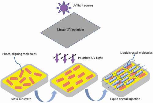
Photoalignment method applied in this work is shown in . The light intensity at the film position was found to be ~3-6 mW/cm2. Experimental cells, having uniform aligned planar and TN (twisted nematic) configuration, respectively, were prepared, and capillary filled with commercial liquid crystal ZLI4792 (Δε>0) (Merck) in the isotropic phase. The polarisation plane of the UV light was oriented 45° with respect to the filling flow in the liquid crystal cell to avoid any influence of the material flow on the photoalignment of liquid crystal. The gap of the experimental cell used in these measurements was ~5 μm. The quality of photoalignment of the liquid crystal in the cells was inspected by means of optical polarising microscope with cross polarisers after slow cooling of the cell from isotropic phase of the liquid crystal to room temperature and being left for a couple of days at this temperature.
Figure 4. (Colour online) Schematic presentation of the photoalignment process used in this work. Photoalignment layer is illuminated with linear polarised UV light prior assembling the cells. The direction of illumination is done at 0° or 45° angle with respect to the substrate. Usually, illumination at 45° angle is used to avoid formation of domains with reverse pretilt as in the case of liquid crystal alignment with pretilt.
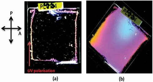
The alignment layer made from PLC242 was found to promote very good planar alignment. The measured contrast of the cell in between the dark and the bright state was 1:1270. The preferred direction of the liquid crystal alignment in the cells was found to be perpendicular to the polarisation direction of the UV light. In fact, the photo-orienting effect in PLC242 under illumination with linearly polarised UV light should be very low since the photo reactive groups are not anisotropic. However, since PLC242 forms a liquid crystal phase, the whole material orients before complete crosslinking and gives high anchoring strength (the magnitude of the anchoring strength in our experimental cell was deduced initially from the amplitude of the director thermal fluctuation in the LC cell, which were very weak, an indication for strong anchoring). This is a highly wanted effect and that is what should be considered, when designing novel photo-alignment materials.
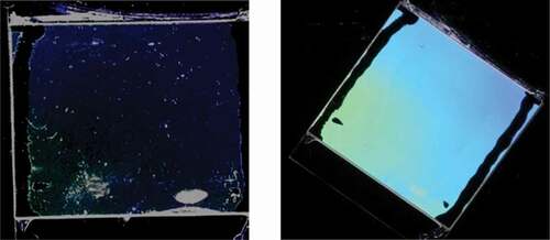
Figure 5. (Colour online) Photograph of a sandwich cell containing photo-polymerised liquid crystalline alignment layer made from PLC242. The alignment layer was illuminated prior assembling the cells with UV linear polarised light at normal incidence. The cell was filled with ZLI4792 and placed in between two crossed polarisers with easy axis direction a) parallel to the polariser and b) at 45° with respect to it. The direction of the UV light polarisation is shown in the picture.
To evaluate the azimuthal anchoring strength of the alignment layer made of PLC242, we used the following energy balance giving the azimuthal anchoring strength. To calculate the azimuthal surface energy term, we should find an equation for the balance between surface and volume elastic forces.
Let us assume that the substrate twist is α and the cell thickness is d. With a director twist of q, the cell twist is Q = d q, and the angle between the substrate alignment direction and the director at each surface should be (α – d q)/2. Then the free energy reads:
where ns1 and ns2 are the directors at the first and second substrates respectively, and W is the azimuthal anchoring strength. If we minimise our expression with respect to q we get:
and thus
Generally speaking, a value of azimuthal anchoring strength corresponding to W ≈ 10−5-10−4 J/m2 or larger is considered as a strong anchoring. For the majority of the photoalignment materials reported in the literature, azimuthal anchoring strength of the order of W ≈ 10−7 – 10−6 J/m2 is considered as weak. For measuring the azimuthal anchoring energy of the photoalignment promoted by PLC242, a TN cell was fabricated and filled with ZLI 4792. It was measured W = 5.8x10⁻⁵J/m2, which could be considered as strong anchoring strength, being enough strong for many device applications. Here we should point out that the polar anchoring energy in most case is equal or stronger (very often one order) than the azimuthal anchoring energy. Therefore, in our study we refer only to the azimuthal anchoring energy because for many liquid crystal and device applications the in-plane switching of the liquid crystal is employed at present, for which the azimuthal energy is of importance.
Photoalignment polymers
Further, we studied the alignment characteristics of one representative of our photoalignment polymer materials, NOA69 (Maleimide-N-vinylpirrolidone), which was designed and synthesised according to our nano-structured alignment materials’ concept. This alignment material was used as a component of the photoalignment composite materials studied in this work.
NOA69 is a side-chain polymer, containing in its structure 20 wt% photosensitisers being a mixture of two types of benzophenones. The alignment layer made from NOA69 promotes vertical alignment and uniform planar alignment before and after illumination with linear polarised UV light, respectively.
Before assembling the experimental cell, the cell substrates were covered with NOA69 alignment layer, which was deposited from 1 wt% in PMGEA and heated to 100°C for 15 min, to get rid of the solvent. The absorption spectrum of NOA69 showed maximum at 295 nm and saturation time about 2 min. The alignment layer was illuminated at normal incidence for 15 min with a linearly polarised UV light with intensity of 5 mW/cm2, passing through 270 nm filter. After assembling, the cell was filled with MLC6873-100 (Δε>0) (Merck). In a photograph of a cell containing photoalignment layer made from NOA69 and filled with liquid crystal MLC6873-100 is shown. The photograph taken when the cell was placed between crossed linear polarisers. The dark state corresponds to orientation of the cell optic axis (the preferred direction of liquid crystal alignment) along the transmission direction of one of the polarisers, whereas the bright state corresponds to 45° orientation of the cell optic axis with respect to the polarisers. As seen, both dark and bright states demonstrate high-quality planar alignment, for which pretilt was found to be 0° and contrast ratio found to be 1:1470. The preferred direction of the liquid crystal alignment was found to be along the UV light polarisation. Intensive thermal fluctuations were observed when the cell was investigated in the polarising microscope. This observation indicated that the anchoring strength is week. Indeed, we found for the azimuthal anchoring strength for this photoalignment material W ≈ 1,48x10⁻⁶J/m2, which is consider as weak.
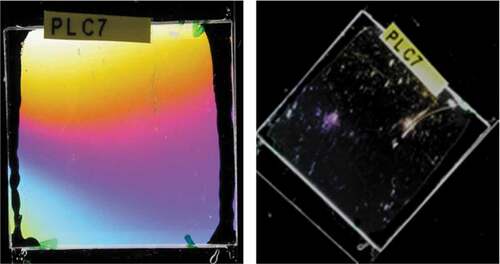
Figure 6. (Colour online) Photographs of a cell containing alignment layer made from NOA 69 (deposited from 1 wt% solution of NOA69 in PGMEA). The alignment layer was illuminated at normal incidence for 15 min with linearly polarised UV with intensity of 5 mW/cm2 passing through 270 nm filter. The used liquid crystal is MLC6783-100. The alignment in the cell was found to be uniform PA with very good quality giving a contrast 1:1470.
Photoalignment composite materials
Photoalignment polymer and liquid crystal material blend
To increase the quality of the photoalignment promoted by NOA69, a composite alignment material, containing 80%wt NOA69 and liquid crystal bulk material 20%wt MLC6873-100, was prepared and dissolved 1% in PGMEA. This solution was spin coated on top of the glass substrates. Then the substrates are baked at 60°C for 15 minutes and after that the alignment layer was illuminated for 15 minutes by UV polarised light passing through 270 nm filter. The polarisation plane of the UV light was oriented at 45 degree with respect to the filling flow in the liquid crystal cell to prevent the influence of the flow alignment. After assembling the cell, liquid crystal MLC 6873–100 (∆ε > 0) was capillary filled in isotropic phase.
As can be seen in , excellent alignment of the liquid crystal with improved dark state was obtained. However, the director fluctuations in the cell, slightly reduced, were still present, thus indicating that azimuthal anchoring is weak – of the order of 10−6 J/m2. This study suggests that the addition of liquid crystal bulk material into the photoalignment polymer enhance the efficiency of the photoalignment ability of NOA69 but it doesn’t improve the azimuthal anchoring strength.
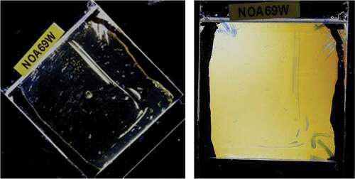
Figure 7. (Colour online) Photograph of the cell containing photoalignment alignment layer made from the photoalignment composition containing 80%wt NOA69/20%wt MLC 6873–100. The cell was filled with the nematic liquid crystal MLC 6873–100. The photograph of the cell was taken in polarising microscope between crossed polarisers. High-quality smooth planar photoalignment was observed in this cell giving a contrast ratio of 1:1560. The areas with different colours correspond to different cell thickness in these areas.
Photoalignment polymer – photoreactive liquid crystal blend
Attempt to increase the anchoring strength of the photoalignment material NOA69 was undertaken by preparing a mixture of the photoalignment polymer NOA69 and photoreactive monomer PLC242, as components of a composite photoalignment material. 1 wt% solution of the composite material 15 wt%NOA69/85%wt PLC242 (mixed with 1 wt% photoinitiator Irgacure784) in PGMEA was spin coated on top of the glass substrates. Then the alignment layer was baked for 30 minutes at 60°C and illuminated for 15 minutes with linear polarised UV light passing through 270 nm filter. After assembling the cell, the cell gap was filled with liquid crystal MLC 6873–100 in isotropic phase by means of capillary forces.
Liquid crystal alignment in the cell, containing the composite photoalignment layer of 15 wt%NOA69 and 85 wt%PLC242 mixture, was found to exhibit enhanced photoalignment quality and strongly reduced director fluctuations, which indicated a stronger anchoring strength when such a photosensitive composite material was used for preparation of the liquid crystal alignment layer. Hence, it could be concluded that adding a photoalignment polymer, such as NOA69, to the photoreactive monomer PLC242, we obtain a composite photoalignment material with improved photoalignment quality and stronger anchoring strength, found to be ~10−5J/m2, that is similar to one measured for PLC242 (c.f.).
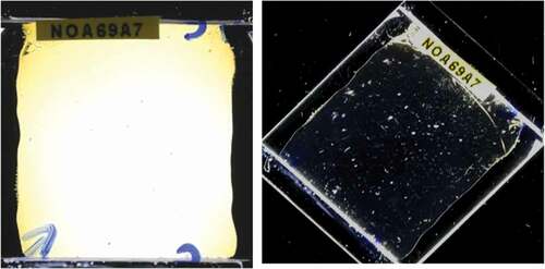
Figure 8. (Colour online) Photographs of a cell containing alignment layer made from a 1% solution of thecomposite 15 wt%NOA69/85 wt%PLC242 dissolved in PGMEA. Excellent dark and bright states of the cell (measured contrast ratio 1:1450) and improved anchoring strength of about 10−5J/m2.
Photoalignment polymer, photoreactive liquid crystal and liquid crystal material blend
The alignment quality was further improved by adding to the composite alignment material NOA69/PLC242 the liquid crystal bulk material MLC 6873–100. Such photoalignment composite, containing the components 20 wt% NOA 69/10% MLC 6873–100/70% PLC 242, was prepared and dissolved in PMGEA in concentration of 1 wt%. This solution was deposited onto the inner cell substrates’ surface by spin coating. The substrates were first backed at 60°C, for 15 min and after that photoalignment film was illuminated at normal incidence for 15 minutes with UV polarised light passing through 270 nm filter. After assembling the cell, the liquid crystal MLC 6873–100 was capillary filled in the cell gap in isotropic phase. The obtained planar alignment in the cell was with higher quality of uniformity and zero pretilt, due to the liquid crystal component, and significantly reduced director fluctuation, that is stronger azimuthal anchoring strength ~10−5J/m2, due to photoreactive monomer LC242 (c.f.). The preferred direction of liquid crystal alignment was found to be parallel to the UV light polarisation.
Figure 9. (Colour online) Photographs of a cell containing alignment layer made from the composite photoalignment mixture 20% NOA 69 + 10% MLC 6873–100 + 70% PLC 242 dissolved in PGMEA in 1%. Excellent dark and bright states of the cell and strongly reduced director fluctuations, indicating strong azimuthal anchoring (estimated to be ~10−5J/m2). Measured contrast ratio 1:1610).
Non-photo sensitive polymer and photoalignment polymer blend
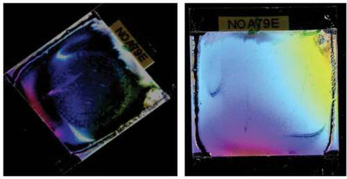
For reducing the time for achieving saturation of the photoalignment effect, a photoalignment composite material, which contains two photosensitive compounds NOA79 and NOA69, was prepared. NOA79, also side-chain polymer, has fluorenone in its molecular structure, which is a well-known photosensitiser. Alignment layer made from NOA79, however, doesn’t show any photoalignment effect on the liquid crystal after illumination with linear polarised UV light. On the contrary, the alignment layer made from NOA69, as described above, promoted a high-quality planar alignment after illumination with linearly polarised UV, passing through 270 nm filter, and intensity of 5 mW/cm2.
These two compounds were dissolved in PGMEA in ratio 90%wtNOA79/10%wtNOA69 and 1% solution of the composite material was prepared. The inner substrates’ surface of the experimental cell was spin coated with this solution and after backing the substrates at 100°C for 15 min, the deposited layer was exposed to illumination with linear polarised UV light passing through 270 nm filter. After assembling, the cell was filled with MLC 6873–100. The addition of just 10% of the photoalignment material NOA69 to the host alignment material NOA79 was found to result in excellent planar alignment with high-quality dark state of the cell between crossed polarisers (measured contrast ratio 1:1710) (). Moreover, it was found that the photosensitivity of this composite material increased substantially. The photoalignment composite material made from NOA79/NOA69 needed less than 1 min illumination with linearly polarised UV and intensity of light of about 3–5 mW/cm2, to obtain a high-quality planar alignment, compared with NOA69, which needed more than 2 min exposure time to reach a saturation!
Figure 10. (Colour online) Photograph of the cell containing photoalignment layer made from the composite90 wt% NOA79/10 wt% NOA69. The cell is inserted between crossed polarisers. High-quality and smooth uniform planar photoalignment were obtained. The areas with different colours are due to different cell gap in these areas. The contrast ratio was measured to be 1:1710.
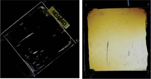
Likewise, the above-mentioned example, the photoalignment ability of the composite material was improved also by mixing two different photoalignment materials such as NOA84 and BHK139. NOA84 is a side-chain polymer containing carbazole, whereas BHK139, also a side-chain polymer, contains benzophenone as photosensitivegroup and increased concentration of alkyl chains in its structure. It was found that NOA84 compound alone doesn’t induce any photoalignment by itself, although the carbazole is a photosensitive group. On the other hand, BHK139 is a photoalignment material having an absorption peak at 294 nm and saturation time of 5 min. The alignment material made from BHK139 was promoting homeotropic alignment of the liquid crystal before UV illumination. If the alignment layer made from BHK139 was illuminated with linear polarised light at incident angle 45° for 15 min, it was promoting alignment with high pretilt ~45-50°.
The photoalignment composition of 90 wt%NOA84/10 wt%BHK139 was dissolved in PMGEA in 1 wt% concentration, which was spin-coated on the cell substrates. After that, the alignment layer was baked at 100°C for 15 minutes and then the alignment layer was illuminated for 15 minutes by linear polarised UV light at incidence angle of 45°, passing through 270 nm filter. After assembling the cell, liquid crystal MLC 6873–100 was capillary filled in isotropic phase.
As it was found that the addition of only 10 wt% of BHK139, which contains about 15 wt% benzophenone, resulted in high-quality tilted photoalignment of MLC 6873–100 promoted by the photoalignment composite material NOA84/BHK139 (). We assumed that the photoalignment ability of the composite material might be due to the phase separation between NOA84 and BHK139. Since BHK139 is a soft material having a lot of alkyl chains it will separate from NOA84 material after heating the photoalignment composite material in such way that it will occupy the top of NOA84 layer to be in contact with the air. Hence, the illumination of the alignment layer made from the photoalignment composite material, containing NOA84 with BHK139, with linear polarised UV light, will enable BHK139 to align the liquid crystal in contact. It should be noted that the BHK139 layer, separated on top of the NOA84, is very thin. Considering that the measured total thickness of the photoalignment layer made from this composite is ~50-80 nm, then the photoalignment component BHK139, being 10 wt% of the total photoalignment material composite, will be separated in 5 nm thick layer. The exposure time for reaching saturation of the photoalignment promoted by this photoalignment composite layer is also short, less than 2 min.
Figure 11. (Colour online) Photograph of the cell containing alignment layer made from 90 wt%NOA84/10 wt%BHK139, inserted between crossed polarisers. Excellent tilted photoalignment with 45° pretilt (indicated by the low birefringence of the cell) and smooth topography was obtained! Preferred direction of the liquid crystal alignment was found to be along the UV light polarisation. The contrast ratio of the experimental cell was 1:1620.
Polyimide alignment material and photoalignment polymer blend
Another approach, we followed within our study, was the preparation of photoalignment composite materials by mixing a conventional polyimide alignment material with some of our photoalignment polymers.
Polyimides are known that at present they are the most appropriate alignment materials for LCDs, due to their robustness and excellent liquid crystal alignment characteristics.
We prepared a photoalignment composite material by mixing a polyamide material with one of our photoalignment materials providing thus a composite material with photoalignment capability, preserving at the same time the excellent characteristics of the polyimide as liquid crystal alignment material. Below is described such an example.
Polyamide alignment material SE7992 (Nissan Chemicals Ltd, Japan) is a conventional alignment material promoting uniform planar alignment of most nematic liquid crystals after the alignment layer made from this material is mechanically rubbed. However, SE7992 is not photosensitive and thus not appropriate as material for photoalignment. But, as we pointed out in the beginning of the article, the rubbing process, although simple and efficient, generates electrical charges and mechanical defects and therefore it is highly desirable to replace this conventional polyamide alignment material by photoalignment alignment material. We found that SE7992 could easily adopt photoalignment property by mixing it with a small amount of one of our photoalignment polymers NOA69, for instance.
SE7992 and NOA69 were mixed in ratio 90 wt%/10 wt%, respectively, in N-methylpyrrolidone (NMP) as 1 wt% solution of the composite. Both materials were dissolved very well in this solvent. The solution was spin-coated on top of the cell substrates. After that the substrates were baked at 100° for 15 minutes, to get rid of the solvent, they were illuminated for 15 minutes by linear polarised UV light passing through 270 nm filter. The substrates were then baked at 100°C for 3 minutes and imidizsed at 180°C for 30 minutes. After assembling the substrates in a sandwich cell, liquid crystal MLC 6873–100 is capillary filled in the cell gap in isotropic phase. Excellent uniform planar alignment, along the light polarisation direction, with very smooth topography, was obtained (c.f. ).
Figure 12. (Colour online) Photograph of the cell containing composite alignment layer made from 90 wt% SE7992 and 10%wt NOA69 taken in polarising microscope between crossed polarisers. The differentcolours in the photograph are due to difference in the cell gap distribution in the cell. The measured contrast ratio of the cell is 1:2150.
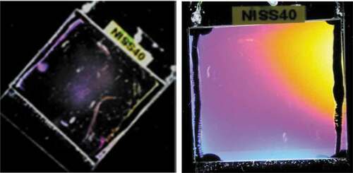
The same composite photoalignment layer was first heated to 180°C for 30 min to imidize first SE7992 component and then the layer was shined with linear polarised UV light. Photoalignment with the same high quality was observed also in this case. This means that a phase separation between SE7992 and NOA69 took place at the first heating of the deposited composite alignment layer to 100°C. The photoalignment mechanism of this photoalignment composite material can be explained on the basis of the phase separation of the two components of this composite material. The polyamide material SE7992 is localised at the solid surface because its higher polarity, whereas the photoalignment polymer NOA69 is localised essentially on top of the composite layer. This phase separation process accelerates during the imidization process and NOA69 become partially or completely separated on the top of the polyimide SE7992. As it was pointed out in [Citation16], a very tiny part of the upper part of the alignment layer (usually few nanometre) is playing an essential role for the alignment of liquid crystals in contact with the alignment layer. Therefore, we can conclude that the very thin layer of the photoalignment compound NOA69 of the composed photoalignment material meets the liquid crystal and imposes a planar alignment with preferred direction along the polarisation direction of the UV light. From these two last experiments can be concluded also that the imidiziation process does not disturb the photoalignment ability of this photoalignment composite layer indeed. It should be also mentioned that in the cell with photoalignment composite layer, the director fluctuations were completely suppressed, indicating thus strong anchoring strength. Indeed, our measurements have shown that the azimuthal anchoring strength in the case of this composite photoalignment layer (2.73x10⁻⁵ J/m2) is an order stronger than the one measured for NOA69 (1.48x10⁻⁶ J/m2). This is very important result giving a guideline how the anchoring strength of the liquid crystal alignment, promoted by the photoalignment materials, could be tailored from weak to strong.
Photopatterned liquid crystal alignment by means of composite photoalignment layer
For generation of less viewing angle-dependent images, photopatterning of the alignment of the liquid crystal is used in some LCDs. The composite photoalignment materials successfully could be employed as materials for photopatterning in the LCDs. Below is given one such example for photopatterning of the liquid crystal alignment by one of our photoalignment composite material.
On both cell substrates was deposited conventional alignment film from 5 wt% solution of SE1211 (Nisan Chemicals Ltd) in NMP. SE1211 is alignment material promoting vertical alignment of liquid crystals. First, the deposited film of SE1211 was baked at 100°C for 3 minutes and then imidized at 180°C for 30 minutes. On top of the SE1211 layer of one of the substrates is spin-coated a photoalignment layer from 1 wt% solution of BHK139 in PGMEA. The photoalignment material is BHK139, one of our photoalignment polymers. It promotes vertical alignment of nematic liquid crystals before illumination with linear polarised UV light, as it was mentioned already. After illumination, however, the alignment layer made from BHK139 is promoting planar alignment with preferred direction along the UV light polarisation.
After deposition, the photoalignment layer made from BHK139 was baked at 100°C for 15 minutes. After that, it was illuminated for 15 minutes with linear polarised UV light passing through 270 nm. filter and quartz mask. The illuminated parts of BHK139 became insoluble, whereas those parts, being light protected, were soluble in solvents such as chloroform. Hence, dipping the illuminated substrate in chloroform, only the illuminated areas of BHK139 were preserved, whereas the light protected areas were dissolved. After assembling the experimental cell, liquid crystal MLC 6873–100 was filled in the cell gap in isotropic phase by capillary forces.
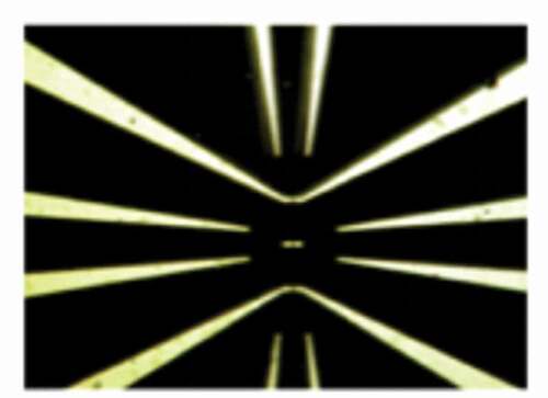
Excellent patterned photoalignment image was obtained in the cell with vertical alignment in the light protected areas and Hybrid Nematic Alignment (HAN) in the illuminated areas (see ). Big advantage of this method is that it gives extremely good dark state with high uniformity (improved surface topography) and therefore the measured contrast of the experimental cell is high (1:2250). As seen from the , the printed image possesses high resolution, limited only by the image exposure system (c.f. ).
Figure 13. (Colour online) Photograph of cell containing alignment layers made from 5 wt% SE1211 deposited on both substrates and 1 wt% BHK139 on top of the SE1211 layer on one of the substrates. The substrate covered with BHK139 is shined through quartz mask and dipped in chloroform. Vertical alignment was observed in the light protected area. High-quality dark state is observed in this cell exhibiting contrast ratio 1:2210.
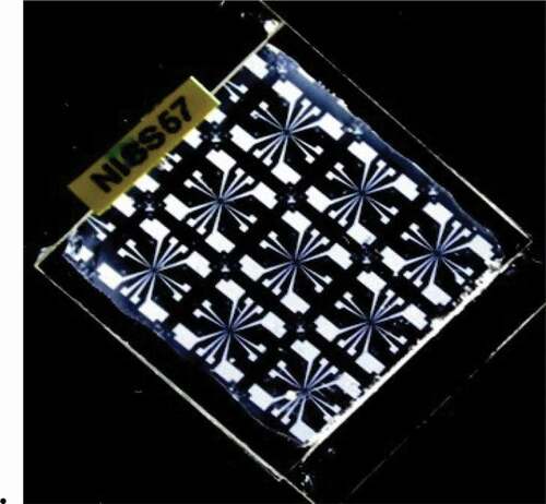
Figure 14. (Colour online) Magnified segment from the observed under polarising microscope. The quality of the photoalignment is excellent and resolution of the pattern is very high. The distance between the two spots in the centre of the figure is 2 µm.
Finally, it is important to mention that for deposition of the alignment layers in this work was used spin-coating technique. The alignment layers in all cells were deposited from 1 wt% solution of the alignment components, which resulted in alignment layers of 50–70 nm thickness with good uniformity.
Conclusions
The results obtained in this study showed that the quality of liquid crystal alignment layers made from photoalignment composite materials could be substantially improved by appropriate choice of their components:
photoalignment polymer
photoreactive liquid crystal monomer, and/or
liquid crystal monomer
We demonstrated how conventional polyimide materials, broadly used as liquid crystal alignment materials in the LCD industry, can easily be converted, in highly sensitive photoalignment composite materials, being appropriate for use in the Liquid Crystal Display technology.
The employment of photoalignment composite materials for achievement of high-quality liquid crystal photoalignment enables to tailor the photoalignment properties of these material in a very broad range resulting in, high sensitivity, and thus shorter exposure time, uniform and smooth photoalignment topography (without domains and sandy structures and thus exhibiting high contrast), high resolution and stability. Finally, high VHR and low RDC of the liquid crystal device, in which the alignment layer is made from such composite photoalignment material are employed, can be also obtained. As known, the characteristics of LCDs, such as VHR and RDC, are of vital importance. These characteristics, however, depend strongly not only on the alignment material and preparation technology but also on the liquid crystal, filling the gap between the device substrates.
In this work some of our photoalignment materials wre used, which were tested for LCD application by us as well as by our partner Nissan Chemical Industries Ltd. The measured VHR and RDC for these materials were in the interval of 98.2 − 99.8 and about 0.01–0.05 V, respectively, depending also on the liquid crystal material, which was used in the LCDs. We assume that VHR and RDC of the LCD, employing the photoalignment composites, remain almost the same as those of the photoalignment component, although the composite of the other component is either photoreactive liquid crystal monomer or liquid crystal monomer. We do also expect that in the case of composite photoalignment materials having polyimide and one of our photoalignment material as components, VHR and RDC of this kind of photoalignment composite will meet the requirements of LCD industry if each of these components does. The photoalignment composites studied in this work were also shown high photosensitivity, smooth topography and the experimental liquid crystal cells containing photoalignment layer made of such composite materials, exhibited high contrast.
We also demonstrated a photopatterning using composite alignment layers consisting of conventional polyimide material and photoalignment material as alignment layer deposited on top of the polyimide alignment layer. Such technology will benefit from the extraordinary electrical and thermal stability of the polyimide material and high photosensitivity of our photoalignment material.
Acknowledgments
In this work participated members of the formal Liquid Crystal Physics Group at the University of Gothenburg, Sweden. We gratefully acknowledge the participation of Dr. Bertil Helge and Dr. Nils Olsson, in the design and synthesis of the photoalignment polymers, and Dr. Ingolf Dahl and Dr. Rasha Saeed, for performing some of the experiments. Many thanks to Nissan Chemical Industries Ltd, Japan, in particular Dr.h.c H.Fukuro, for the generous and strong long-term support of our common project in the area of “Alignment materials for LCDs”.
Disclosure statement
No potential conflict of interest was reported by the author(s).
References
- Cognard J. Alignment of nematic liquid crystals and their mixtures. Mol Cryst Liq Cryst Suppl Ser. 1982;1:1–78.
- Chatelaine P. Orientation of liquid crystal. Bull Soc Franc Miner. 1943;66:105.
- Berreman DW. Solid surface shape and the alignment of an adjacent nematic liquid crystal. Phys Rev Lett. 1972;28:1683.
- Berreman DW. Alignment of liquid crystals by grooved surfaces. Mol Cryst Liq Cryst. 1973;23:215–231.
- Janning JL. Thin film surface orientation for liquid crystals. Appl Phys Lett. 1972;21:173.
- Chigrinov VG, Kozenkov VM, Kwok N-S. Photoalignment of liquid crystalline materials. England: John Walley&Sones Ltd; 2008. DOI:https://doi.org/10.1002/9780470751800.
- Yaroshchuk O, Reznikov Y. Photoalignment of liquid crystals: basics and current trends. J Mater Chem. 2012;22:286.
- Gibbons WM, Shannon PJ, Sun ST, et al. Surface-mediated alignment of nematic liquid crystals with polarized laser light. Nature. 1991;351(6321):49–50.
- Schadt M, Schmitt K, Kozinkov V, et al. Surface-induced parallel alignment of liquid crystals by linearly polymerized photopolymers. Jpn J Appl Phys. 1992;31:2155–2164.
- Schadt M, Seiberle H, Schuster A. Optical patterning of multi-domain liquid-crystal displays with wide viewing angles. Nature. 1996;381:212–215.
- Dyadyusha AG, Kozenkov VM, Marusiy TY, et al. Light-induced planar alignment of nematic liquid-crystal by the anisotropic surface without mechanical texture. Ukr Fiz Zh. 1991;36(7):1059–1062.
- Dyadyusha AG, Marusii TY, Reshetnyak VY, et al. Orientational effect due to a change in the anisotropy of the interaction between a liquid crystal and a bounding surface. JETP Let. 1992;56(1):17–21.
- Ichimura K. Photoalignment of liquid-crystal systems. Chem Rev. 2000;100(5):1847–1874.
- Press release: sharp to incorporate UV2A technology into production of LCD panels, September 16, 2009. http://global.sharp.
- Komitov L, Helgee B, Felix J, et al. Electrically commanded surfaces for nematic liquid crystal displays. Appl Phis Lett. 2005;86:023502.
- Liquid Crystal Device and a Method for Producing it Having Directly Controllable Dynamic Surface-director Alignment Layer, US 6,549,255 B2; A Liquid Crystal Device A method for Producing a Liquid Crystal Device and Method for Controlling a Liquid Crystal Device, WO 03/081326 A1; Maleimide-N-Vinyllactam Based Side-chain polymers for LCD alignment layers CN ZL200980152980.8, KR 10-1612725, TW I50198; Composition for LCD alignment layers, JP6138102, CN Zl 200980159279.5, TW I5360; Polymer for Use in Alignment Layer, JP 6192710, CN-ZL20128007283.2, TW I 598406, KR 10-1951267
- Guo Q, Srivastava AK, Chigrinov VG, et al. Polymer and azo-dye composite: a photo-alignment layer for liquid crystals. Liq Cryst. 2014;41(10):1465–1472.
- Tseng MC, Yaroshchuk O, Bidna T, et al. Strengthening of liquid crystal photoalignment on azo dye films: passivation by reactive mesogens. RSC Adv. 2016;6(53):48181–48188.
- Komitov L, Bertil H, Nils O, et al. New generation of VA materials for LCDs. Presentation at IDW. 2011, 7-9 December, Nagoya, Japan.
- Komitov L, Bertil H, Nils O, et al. New generation VA materials for flexible liquid crystal displays. Presentation at IMID. 2012, 28-31 August, Daegu, Korea.
- Komitov L. Nano-engineering of the anchoring of liquid crystals on solid surfaces. Thin Solid Films. 2008;516:2639–2644.
- Knoblauch C, Enger. OC, Schalkowsky UD. Novel polymerisable liquid crystalline acrylates for the manufacturing of ultrathin optical films. SID’06 Digest. 2006; 1673. https://doi.org/https://doi.org/10.1889/1.2433327