
 ?Mathematical formulae have been encoded as MathML and are displayed in this HTML version using MathJax in order to improve their display. Uncheck the box to turn MathJax off. This feature requires Javascript. Click on a formula to zoom.
ABSTRACT
In ancient Roman religion and myth, Janus is the god of beginnings, gates, transitions, time, duality, doorways, passages, frames, and endings. He is usually depicted as having two faces looking in opposite directions, one towards the past and the other towards the future. This article is dedicated to Professor BK Sadashiva for his contributions to the science of liquid crystals, and new beginnings in the design and creation of mesomorphic materials.
In the studies of metallomesogens based on copper(II) complexes of β-diketones, Ohta and his colleagues reported the first-established discotic-lamellar phase, in which the board-like complexes are able to form lamellar packing arrangements, and at the same time stacking into columns. Casagrande et al. later prepared synthetically modified beads with one hemisphere being hydrophobic and the other hydrophilic. These particles were considered to be amphiphilic solids, and called Janus Beads. Synthetic Janus Mesogens with supermolecular architectures having one chiral nematic hemisphere and the other with smectic tendencies were made in 2003. These complexes, particles, and supermolecules, were termed Janus to describe the structure of the material. In this article we use Janus liquid crystals to describe a material that combines two different packing motifs in a single uniform phase structure.
Graphical abstract
1. Background
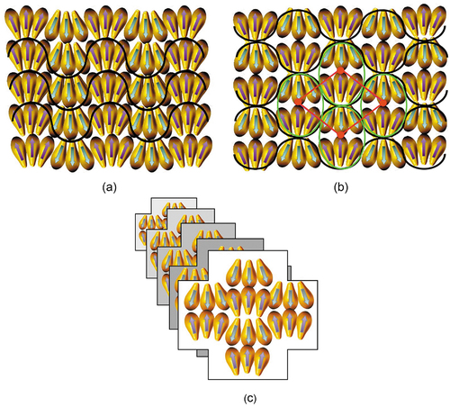
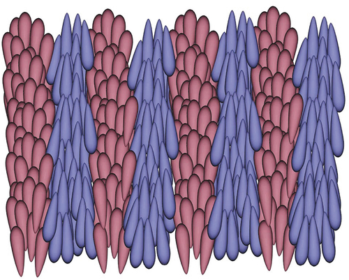
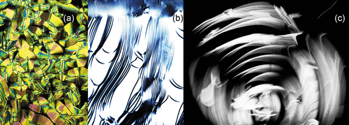
In 1988 Chandrasekhar, Ratna, and Sadashiva reported that the copper(II) complex of 1-(4ʹ-decylbiphenyl-4-yl)-3-(4-methylphenyl)propane-1,3-dione, 1, shown in ), and its analogues exhibited the first example of a biaxial nematic phase [Citation1]. This discovery was thought to be the pinnacle in the search for biaxial nematogens, which had primarily focused on the mesomorphic properties of copper(II) complexes of β-diketones. However, biaxiality could not be conclusively proven and the materials and their properties remain curiosities [Citation2]. Nevertheless, earlier in 1986 Ohta et al. [Citation3,Citation4] reported on the first discotic-lamellar phase, which was found in the biaxiality related bis-[l,3-di(4-n-alkoxyphenyI) propane-1,3-dionato]copper(II) family of complexes, 2, as shown in ). Studies involving X-ray [Citation5] and NMR spectroscopy [Citation6] indicated that the discotic phase consisted of a so-called ‘rigid smectic phase’ where the ‘rotationally restricted’ board-like molecules packed into relatively loose columns, which laid side by side in the lamellar phase as shown in , hence Ohta’s classification of the phase as discotic-lamellar. Thus, depending on one’s point of view of the structure, this phase can be either columnar or lamellar, and therefore we can describe the mesophase as Janus. Subsequent studies on compounds with the rod-like structures, 3, see ) were also shown to exhibit discotic-lamellar phases [Citation7] indicating that it is not necessary to have molecules with board-like architectures to exhibit these properties, indicating the Janus nature is not necessarily dependent on molecular structure.
Figure 1. Materials thought to exhibit biaxial nematic phases (a), and discotic-lamellar phases (b and c).
Figure 2. The proposed structure of the discotic-lamellar phase.
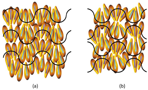
Here, we diverge from the now common usage of Janus in Liquid Crystals. Typically, Janus is used to describe molecular architectures found in dendritic and supermolecular materials [Citation8,Citation9] an example of which is shown in . The structure of this material is composed of two joined hemispheres, which if they were isolated and on their own would exhibit different mesophase behaviours, yet when joined together exhibit only one mesoform as shown in the figure [Citation10,Citation11]. These types of material and their phase behaviours are not the subjects of this article, and instead we focus on materials that combine two different packing motifs in a single uniform phase structure.
Figure 3. A typical Janus material composed of separate hemispheres which when separated would exhibit different mesoforms, but when joined exhibit a single mesophase sequence [Citation11].
![Figure 3. A typical Janus material composed of separate hemispheres which when separated would exhibit different mesoforms, but when joined exhibit a single mesophase sequence [Citation11].](/cms/asset/ac049e11-7fb9-4671-866b-7a6c261f0f41/tlct_a_2002445_f0003_b.gif)
In the following, we look at a variety of systems where phase structures and behaviours appear to be associated with different phase types associated with one molecular architecture. The object of this report is firstly to clarify mesophase behaviour as a function of temperature and chemical architecture, secondly to explore how microscope defect textures are associated with these behaviours, and thirdly how these observations affect mesophase classification. We start with some phase behaviours and phase types that can depend on how one observes them, for example, by microscopy, X-ray diffraction, etc., and how modulations in structure can be used to build-up an overall picture of molecular organisation in fluid and rotationally disordered mesophases. Thus, we start with related phases that are said to possess one-dimensional modulated structures.
2. In-plane modulations or harmonics
In this section, we examine mesophases formed by rod-like molecules that pack together in layers. The possible arrangements we assume are split into three types; (i) where the molecules have long-range positional ordering, (ii) where the periodic ordering exhibits algebraic decay [Citation12], and (iii) where the ordering is short-range exhibiting exponential decay. The translational ordering of the molecules within the layers can take a wave-like or harmonic form described as 1D modulations [Citation13,Citation14].
For liquid crystal phases increasing decay or ordering within a mesophase occurs as the temperature is raised, or alternatively during the pre-transitional region occurring before a transition to a less-ordered state. Thus, it is possible to move from long-range to short-range ordering via modulation damping, where damping is the absorption of the energy of molecular oscillations, by whatever means, resulting in the reduction of the natural frequency of a system, via the dissipation of energy from the vibrating structure. The order of mesophase types to be examined in the following is related to their discovery, starting with the antiphases SmA and SmC.
2.1 Smectic antiphases and columnar phases
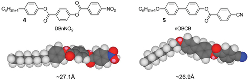
We begin with the investigation of Janus Mesophases based on Antiphases. So-called ‘Antiphase’ liquid crystals are mesophases usually composed of strongly polar rod-like molecules where their packing can be commensurate or incommensurate dependent on length (molecular pairing) resulting from the formation of nematic and smectic phases where reentrancy can readily occur [Citation15–18]. The strong polarity of these materials can arise from conjugated terminal groups based on nitro- and nitrile-moieties. Commonly antiphase materials have multiple aromatic units linked together by ester groups that are partially conjugated, as shown by the DBnNO2 and nOBCB structures in . For these families of materials the terminal groups have an opposing electron distribution with respect to the carbonyl moieties of the ester units; this causes disruption to the packing of the molecules in their smectic layers whereupon monolayer and bilayer ordering can occur resulting in incommensurability with the disruption sometimes inducing reentrancy. In some cases there is also the possibility of in-plane modulations of the up and down orientations of the molecules, which can result in the formation of ‘tilda’ phases. In these systems the molecules can be either upright or tilted within the layers to give smectic A and smectic C variants, ie SmA1, SmA2, SmAd and Smà phases and their smectic C analogues. The in-plane modulations or harmonics for these phases may be referred to, or appear as, one-dimensional, and in such a case they should decay because of the possibility of ‘Peierls’ distortions breaking up perfect long-range order. This would be in keeping with the dynamic motions and fluctuations of the molecules giving liquid-like layers [Citation12], which may be at odds with the cartoons that show that there is in-plane ‘blockiness’ in the structures of antiphases.
Figure 4. (Colour online) Homologous series of materials that possess Antiphases. Molecular modelling was performed using ChemDraw 3DTM.
If we look at the molecular packing and dynamics in antiphase materials, we see how in-plane distortions might occur, and the possibilities of forming undulating layers. For example, both of the families shown in possess molecules pictured as being rod-like, but this is not true from the points of view of steric shape, electron density, and motion. In fact, considering that the molecules are rotationally disordered they are slightly pear-shaped dependent on the aliphatic chain length. Thus, antiphase behaviour starts to occur in both homologous series as the aliphatic chain length increases past seven methylene units. The pair-shaped nature of the molecules can introduce curvature to the packing organisation, such that time dependent clustering can occur, in doing so this process minimises both the curvature and the polarity of the overall system, thereby reducing the free energy.
For monolayer phases, the clustering can occur within the layer planes causing in-plane modulations. Sometimes this is shown as a jump in the packing from clustering periodically to molecules pointing up to then molecules pointing down. However, there is no rationale for this being the case. It is more likely that the viscoelastic forces will produce a harmonic arrangement of the molecules within the layers so as to retain the layer order without large-scale disruption or periodic defect walls. The outcome of this argument is two-fold; in order to retain the layering and reducing the free energy, the in-plane modulations between layers should be either in-phase or out-of phase by 180°, as shown in (a and b), respectively. In the generalised first situation, polar ribbons are formed in an antiparallel splay arrangement such that the overall polarity is zero. In the second, clusters of zero polarity are formed between layers such that local rectangular arrays are generated, as shown by the red line in the figure. In this case the local molecular polarity is also cancelled, however, the rectangular array resulting in a soft lattice means that this will be the lower temperature of the two phases. In terms of the lattice dimensions, one might expect that they will be related to molecular length, or multiples thereof. This is then the simple situation for monolayer systems, whereas antiphases typically occur for materials that exhibit bilayer structuring. Although for reasons of universality depicts two simple structural arrangements for in-phase and out-of-phase modulations in an unspecified monolayer system, if one were to use the models in terms of real phases, structure (a) may represent a non-centred rectangular lattice (Colr), (maybe Colrp to be more specific), and a SmC-like in-phase modulated phase then would have an oblique lattice (Colob), whereas structure (b) with a SmA-like 180° out of-phase modulated phase is a centred rectangular lattice and would be (Colr); (and again Colrc to be more specific).
Figure 5. (Colour online) Curvature in molecular packing resulting in in-plane modulation within the layers of antiphases; (a) in-phase modulations resulting in a layered phase, (b) out-of-phase modulations resulting in the formation of a columnar phase, and (c) columnar structuring where molecules may be disorganised looking into the page.
In the case of DB9NO2 and 9OBCB both have molecular lengths of approximately 27 Å, whereas the in-plane modulation wavelength has been reported to be in the region of about 40 to 130 Å [Citation19]. Comparing the modulation wavelength with the molecular length indicates that they are of a similar scale to the lattice dimensions for the second variant. Therefore, a phase shift of 180° for the in-plane modulation may result in the formation of a rectangular lattice [Citation19], resulting in the formation of a columnar phase, as shown in ). The two variants will be able to be distinguished in the polarising microscope, as the second variant will exhibit a defect texture that is synonymous with that of a columnar phase [Citation18], as shown in .
Figure 6. (Colour online) Photomicrographs of the mesophases of 4-decyloxybiphenylyl-cyanobenzoate (10OBCB) x100; (a) the texture of the Sm phase formed from the SmA phase, (b) the formation of the Sm
phase in the homeotropic area of the SmA phase on cooling, (c) the texture of the columnar phase of 10OBCB, note the lack of focal-conic defects, and (d) the schlieren texture of the SmC phase formed on cooling the Sm
phase.
The differences and sometimes confusions drawn from classification of mesophases by thermal optical microscopy (POM) can be seen more easily from investigations of the tilted antiphase equivalents. For an antiphase material that exhibits both Sm and SmC phases, the Sm
phase has been reported to appear at higher temperatures than both the SmC phase and SmA2 phases and lower than the SmAd phase [Citation13–19]. For thermal optical microscopy a schlieren texture for the smectic C phase should be observed, but for the Sm
phase the defect texture appears to be associated with that of a columnar phase. For example, the defect textures for the Sm
and SmC phases of the decyl homologue of the 4-n-alkoxybiphenylyl-4ʹ-cyanobenzoates (10OBCB) are shown together in [Citation17]. A photomicrograph taken at a magnification of x100 for the Sm
phase formed from the SmA phase on cooling is shown in ). This paramorphotic texture is based on the focal-conic pattern of the preceding SmA phase, however, there are no elliptical or hyperbolic lines of optical discontinuity that mark the presence of dupin cyclides. Between the fan-like domains the zig-zag defect lines show some degree of long-range ordering. ) shows the transition between the SmA phase and the Sm
phase, where the SmA phase exhibits both focal-conic and homeotropic textures. Interestingly, the focal-conic defects are retained, whereas the homeotropic region becomes patterned with domains of a growing columnar phase, where ) shows the resulting texture of the columnar phase of the Sm
phase. Interestingly, the quadrants associated with the singularities show dark and light areas that are not symmetric, that is, light-dark-light-dark. This may be due to the phase being associated with a tilted columnar structure. The formation of the schlieren texture of the SmC phase found on cooling the Sm
phase is shown in ). This texture is typical of the schlieren of the SmC phase with s = ±1 singularities. Similar observations were also made for the 4-nonyl- and undecyl-oxybiphenylyl-cyanobenzoates (9OBCB and 11OBCB).
In terms of X-ray diffraction studies, Hardouin et al. [Citation19] reported experimental and calculated values for the reticular distances of the Sm phase, and also the corresponding diffracted intensities for the material DB8NO2 (see for the general structure). They used these results to produce a potential structure of the phase, as shown in . The structure was described as possessing molecular layers that are broken into segments of pairs of molecules that have periodic stacking faults, and hence they described the phase as having a ‘ribbon’ structure. They determined the amplitude of the distance between adjacent sigments of the ribbons to be approximately 0.8 x the molecular length. Furthermore, they also described the phase as having regular stacking of bimolecular tilted regions and where two adjacent ribbons can be interlaced. Therefore, they surmised that the oblique lattice is equivalent to a bilayered structure broken periodically by defect walls.
Figure 7. Structure of the smectic phase of DB8NO2.
Thus, they estimate that the Smà phase is c-centred rectangular, as also observed by microscopists.
Examinations of the smectic à and phases of the related materials, such as DB7NO2 and DB8NO2, respectively, were also thought to exhibit walls caused through in-plane modulations in the organisations of the packing arrangements of the molecules, which were likened to the antiphases observed in some alloys, where antiphase boundaries separate adjacent crystals that have the same crystallographic orientation but have a 180° phase shift. Consequently, it seems that antiphases can appear under certain circumstances as a collection of layered phases where the molecules can be orthogonal or tilted (notated as serrated phases in [Citation19]) with respect to the layer planes, and yet such phases can appear as columnar phases often identified as rectangular and classified as Colr, or as oblique and classified as Colob, respectively.
(NB: There are a number of descriptors for these modulated phases, that is, antiphase, serrated, and subclasses of columnar phases, therefore it might be beneficial to simplify their classification. Therefore, for these Janus Liquid Crystals we suggest retaining the use of both antiphase and columnar classifications, and where appropriate to describe particular sawtooth structures we will continue with the use of ‘serrated’.)
In the cases of the nitro-substituted antiphase liquid crystals, the temperatures where such phases exist are in the region of 90 to 110 degrees resulting in the occurrence of substantial molecular fluctuations. In addition, chemical degradation may have started in relation to molecular oxidation, as shown by DSC and POM. Moreover, if the experiments had been performed on cooling so that paramorphosis of the solid was appropriately suppressed, the high temperatures (>200°C) involved in the process of cooling from the liquid state would have incurred much higher degrees of degradation. Internally the defect walls in the smectic antiphases therefore will be relatively disorganised and act as nematic disclinations, with their periodicity determined by splay elasticity related to the packing of strongly polar paired molecular grains, with the consequence of minimisation of the free energy. In terms of the examinations of such phases, they will appear to be columnar or lamellar from the point of view of POM, however, their lattice cells indicate that they are in-plane 1D-modulated smectic phases with modulations 180° out-of-phase with one another, as shown in . The packing of the molecules as shown demonstrates that the lattice is unlikely to be hexagonal as the molecules are not radially packed, but are on average parallel to one another resulting in a rectangular or rhombic arrangement.
Figure 8. The fluid-like structure of the antiphase smectic C phase where the molecules are shown as being polar rods (as arrows) that interact strongly together (head to head). An example of a mesophase with such a structure could be an oblique lattice (Colob).
Consequently, it seems that antiphases can appear under certain circumstances as a collection of layered phases where the molecules can be orthogonal or tilted with respect to the layer planes, and yet such phases can appear as columnar phases often identified as rectangular and classified as Colr. Moreover, both types/forms of mesophase can be observed by X-ray diffraction (XRD) and thermal polarised microscopy (POM). Probably because the molecules are rod-like the classification as smectic phases has taken precedence. In terms of the usage of the term columnar, it was originally introduced to replace the terminology ‘discotic’ to describe mesophases composed of disc-like molecules. This resulted in a problem with respect to nematic phases composed of disc-like molecules and naming mesophases by chemical type instead of realising that nematic phases made up of rods or discs were the same nematic phases. To alleviate this problem we will apply columnar in terms of mesophase structure, rather than in terms of molecules or molecular shapes.
2.2 Bent-core materials and the columnar and B phases
Second examples of phases that possess 1D in-plane modulations and columnar phases are based on so-called ‘bent-core’ or ‘banana’ mesogens. [The nomenclature used for bent-core phases is still not fully formalised, but the original Bn system of B1 to B8 relating to their historical discovery is still in common use, however, phases like the B1 phase has also been designated as SmA’b or Colr.] [Citation20].
Two such compounds that exhibit the B1 phase [Citation21–23] are shown in , where a conventional bent-core material with a stiff central core region is shown in the upper part of the figure, whereas a material that has a hinge point in the centre of its molecular structure is shown in the lower part in its keto form, although it should be noted that it can also transform into its enolic form.
Figure 9. (Colour online) For top and bottom there are two different bent-core mesogens, with their phase transition temperatures given in °C. The upper compound, 6, has a fairly rigid central aromatic core section, whereas the lower compound, 7, can rotate to some degree around the central linkage. Both materials exhibit B1 phases. The two photomicrographs show the dendritic growth of the B1 phase from the isotropic liquid for the two arrowed materials.
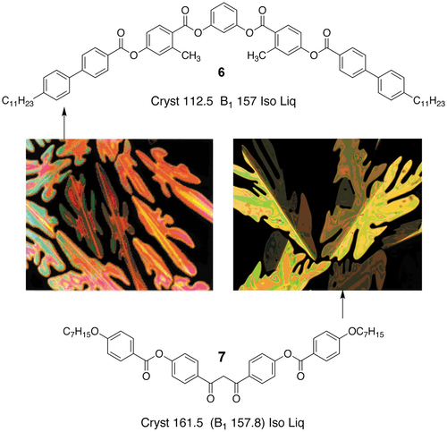
The defect textures of the B1 phases of the two materials are also shown in the centre of the figure [Citation20,Citation24]. The B1 phases of both materials are shown forming from the isotropic liquid in dendritic growth patterns. Additionally, the textures show optical discontinuity or defect lines down the centres of the dendrite arms; these are typically found in solid-state crystal growth where the crystal tends to branch into two parts during growth. For the dione (keto) compound, 1,3-bis-(4-(4-(heptyloxy)-phenylcarbonyloxy)phenyl)propane-1,3-dione, the defect lines are at an angle of ~69° indicating that the phase has a rhombic structure (unit cell). Thus, the two defect patterns indicate that the B1 phase has long-range periodic order, and is akin to being a soft-crystal phase, that is, the B1 phase is more ordered than the antiphase systems described previously. X-ray diffraction patterns of the dione compound, see , also show the presence of long-range ordering from the inner rings of the B1 phase, see ),
Figure 10. X-ray diffraction patterns for 1,3-bis-(4-(4-(heptyloxy)-phenylcarbonyloxy)phenyl)propane-1,3-dione. (a) the diffraction pattern for the crystal form, (b) the pattern for the B1 phase at 144°C, and (c) the pattern near to the transition from the liquid at a temperature of 157°C. Since the B1 phase is monotropic all experiments were performed on cooling from the liquid.
Figure 11. (Colour online) The structure of the B1 phase. The molecules are shown as bent rods where the red and yellow ellipsoids are mesogenic units, the metal looking linkage may be a rigid group as found in bent-core mesogens, or alternatively it may be flexible as seen later in the design of materials that exhibit NTB phases.
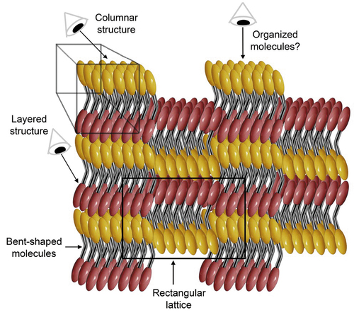
It appears that the proposed structure of the B1 phase is remarkably similar to the structure of the smectic A antiphase (SmÃ) except for the molecules being effectively two mesogenic units (red and yellow in ) linked together (silver) to give bent-shaped molecules that span across the layers. The linkage in this system is usually an aromatic ring or it can be a flexible chain as described later for the NTB phase. As the molecules are strongly polar, with the dipoles pointing between the two arms, the packing together of the molecules and rotational hindrance about the longer axis serves to affect the overall polarity. For instance, steric hindrance will locally hinder adjacent molecules pointing opposite ways, instead from the point of view of packing the bent-shaped molecules will prefer to nest together. Consequently, in this arrangement the molecular dipoles will point in the same direction giving the system overall polarity. However, if small clusters of molecules are formed with their dipoles pointing in the same direction, and are allowed to oppose similar clusters with the dipoles pointing in the opposite direction, then the overall polarity of the phase is brought down to zero. This clustering will be expected to be of molecular dimensions, as shown, with the clusters forming alternating columns, hence the B1 phase is also said to have a columnar classification. A further consequence is that the clusters will move up and down in the layers depending on the direction of the molecular bends as shown in . An outcome of these arrangements is that on looking into the layering a rectangular unit is seen, shown by the black lines in the figure. No matter what the system, this arrangement for molecules that are longer than broader will always result in a rectangular unit cell, and unit cells based on hexagonal arrangements do not occur. This means that structures like the B1 phase will always be identified as Colr or Colob phases and appear in the microscope as mosaics not too dissimilar to those exhibited by crystal B phases or crystal G phases.
Turning now to the nature of the B1 phase, is it crystalline or liquid crystalline? In the B1 phase the arrangements of the molecules would need to be extensive in three dimensions for the B1 to be stable, but it would be crystalline provided that the centres of the molecules have periodic order. This is the one aspect of the structure of the B1 phase has not been fully investigated. Within the clusters the molecules can be randomly organised and not necessarily hexagonally or rectangularly close packed. The result of the diffusive local packing is that the clustering and packing will be not as clear cut as shown in the figure, and as one moves from one area to another there will be molecular disordering, and again in the planes of the layers the molecular density will exhibit modulations as in the antiphase. However, the wave-forms of the modulations will be tighter than in comparison to antiphases, and it is the modulations not the molecules that determine the lattice periodicity. Thus, the B1 phase is also reported to be a rectangular columnar phase [Citation21] rather than an antiphase. Indeed, if reported as being 3D-modulated then it might be considered as a crystal.
The B1 phase has also different variants, that is, the B1rev and B1revtilt, which can exhibit columnar phases akin to the SmA and SmC antiphases. The B1 phase can also be formed on cooling from the nematic phase as shown for the compound at the top in . This material has a central naphthalene unit, which seems to impart a tendency in supporting the formations of more disordered phases such as the nematic phase. It would be also interesting to know if the nematic phase in this case is similar to the splay nematic phase described in the following section.
Figure 12. Top, a bent-core material, 8, that exhibits a B1 phase formed on cooling a nematic phase, and bottom a dimer, 9, composed of bent-core mesogenic units joined together via a methylene spacer of odd parity. The dimer is reported to exhibit a columnar phase [Citation28]. The phase transitions are given in °C.
![Figure 12. Top, a bent-core material, 8, that exhibits a B1 phase formed on cooling a nematic phase, and bottom a dimer, 9, composed of bent-core mesogenic units joined together via a methylene spacer of odd parity. The dimer is reported to exhibit a columnar phase [Citation28]. The phase transitions are given in °C.](/cms/asset/ee66f7da-6732-4cfc-9bbf-4e32693631f2/tlct_a_2002445_f0012_b.gif)
Extensive studies have also been made into the relationships between complex molecular architectures and the incidence of various mesophase types. Again, it is quite common to see materials having liquid crystal phases labelled as columnar, smectic and B-type (for bent-core liquid crystals). For example, the dimeric material shown by the lower structure in is identified as having a columnar phase, and others have been specifically identified as having oblique columnar phases, which might be similar to smectic C antiphases. The interesting point to be made about these dimers is that they have methylene linking groups that are odd in number, whereas in comparison, similar dimers with rod-like mesogenic units and flexible linking units tend to exhibit twist-bend phases (see later) [Citation25,Citation26]. Increasing the molecular complexity to tetramers and systems with siloxane linking groups and bent-core mesogenic arms appears to revert to systems being lamellar, indicating that such bent-core systems have the ability to exhibit wide-ranging polymorphism with the possibility of showing Janus behaviour [Citation27].
2.3 The splay nematic phase and discotic nematic phase
Turning now to lesser-ordered systems, we examine the new splay nematic phase classified by the code letter as Ns. It should be noted that two other names, PN and NF, have appeared based on the properties of polarity and ferroelectricity, respectively. This phase was first encountered in research work at the University of York. In a programme starting in 2008, and funded by the EPSRC and QinetiQ, novel liquid crystals possessing nitro functional groups were targeted for applications in electronic devices. The nitro-content was to be proportionally optimised within the molecular architecture so that it would provide substantial polarity to the material. In material design, this meant minimising the lengths of alkyl substituents. In the design there was also a realisation that terminal nitro groups did not readily support the formation of nematic phases to the same extent as nitriles, and therefore the first targets were based on utilising DB7ONO2 as a model system because it, and its analogues, readily supported nematic behaviour. The orientations of the ester groups within the target molecular architectures were chosen so as to maximise the polarity of the molecule along the longitudinal direction without resorting to additional lateral functionalisation (e.g. fluoro). Lateral substitution was instead used in two ways, one to lower the melting temperatures hence aiming towards room temperature, and secondly to suppress smectic phase formation while at the same time relatively raising nematic phase stability. Thus, the design and preparation of RM230 and RM734, see , were not totally accidental, and they were initially synthesised in 2009 [Citation29]. Details of the design strategies for RM230 and RM734 are given in references [Citation30–34].
Figure 13. The structures and phase transitions (°C) of compounds RM230 and RM734.
A cartoon of the proposed splay structure [Citation35] of the nematic Ns phases of RM230 and RM734 are shown in . In this picture, the pear-shaped molecules either point up or down in a semi-ordered way relative to the director, but in reality they will be more mixed up than is shown. If one assumes that the molecular dipoles point towards the bases of the pears the overall structure will have zero polarity. However, once subjected to an applied field the molecules will be poled and point roughly in the same direction, but once the field is removed they should return to the ground state of zero polarity. With appropriate aligning fields this may not occur and the phase could be said to be polar and support ferroelectric behaviour [Citation36–38].
Figure 14. (Colour online) A cartoon of the proposed structure of the splay nematic (Ns) phase.
Returning to the bulk state for the Ns phase, in comparison to the antiphases of the DBnNO2’s it is possible that the Ns phase may possess a modulation perpendicular to the director of the phase, as shown in . However, unlike antiphases the molecules might be expected to have a more jumbled up arrangement, but like antiphases there is a possibility that modulations may be either in-phase or out-of-phase as shown. In-phase modulations produce an arrangement as proposed for the structure of the splay nematic phase [Citation32–35], see ), whereas out-of-plane modulations will produce a novel form of the nematic phase, see ), and as a consequence in both cases the overall structure will have zero polarity. This prediction was made recently, and at a similar time experimental evidence for the presence of a Ns discotic phase was made in a report by Saha et al. [Citation39].
Figure 15. (Colour online) Potential structures of modulated splay nematic phases, (a) in-phase modulations, and (b) out-of-phase modulations.
The presence of modulations in the splay nematic phase is indicated by the formations of filaments. Cladis and Brand reported splay line-defects as sometimes forming hedgehog and antihedgehog pairs [Citation40], which upon annihilation give static solitons. ) shows the formation of filaments at the transition from the nematic to the splay nematic phase upon cooling, upon which the filaments become adsorbed back into the Ns phase. Pairs of s = + and – ½ defects are shown in a blown-up photomicrograph of a filament in ), (highlighted by a white ring). ) shows a picture of a disclination line where filaments may be formed laterally off the centre of the line, as shown in (a) where the disclination line runs down the photomicrograph.
Figure 16. (Colour online) The filamentary texture of the Ns phase (x100) of RM230, at 76°C, forming off the disclination line (a), blow-up of a filament showing singularities, x300 (b), and structure of the splay line disclination (c).
Filaments are quite often found in liquid crystal phases that are formed via a dependency on elastic behaviour. For example, the Ns phase is dependent on splay deformations, the twist bend phase (NTB) is dependent on twist and bend deformations, and the twist grain boundary (TGB) phase is dependent on twist. The TGB phase not only exhibits helical filaments, it also has defect textures that are commensurate with the presence of a columnar phase. The next set of Janus Mesophases thus starts with the first of such phases to be discovered – the twist grain boundary phase.
So far, we have examined the duplicity of phases for 1D-modulated systems. The duplicity usually involves antiphase or columnar structures depending how they are viewed and the experimental analysis is performed and data is collected. It can be seen for families of materials where the molecules have specific steric shapes, sometimes the mesophases formed are classified differently, for example, lamellar, antiphase, columnar, rectangular, bent-core, banana, polarity, etc., depending on the method of analysis, which in turn can lead to confusion.
If we now compare the three liquid crystal phases discussed above we see that they have structural aspects in common; all have layered structures, and all also appear to be columnar (rectangular). In terms of the extent of organisation of the molecules and modulation damping, the Ns phase is least ordered, the antiphases next, and the bent-core systems are the most ordered which can be seen by POM and X-ray diffraction, and all have in-plane modulations. Apart from the shapes of the molecular entities the three fall into the same class and can be arranged in terms of the extent of ordering. For the architectures of the molecules, the mesogens of the Ns and antiphases were rod-like and polar, whereas for the bent-core system the mesogens are bent and polar. Thus having a strong polarity appears to support modulations, but steric shape seems to be less important. However, it should be realised that the contribution of electron distribution to molecular architecture may affect ‘electronic shape’.
A comparison of the modulated phases with the classification of conventional nematic and smectic phases [Citation12,Citation18,Citation41] is given in . It shows a good fit, and no doubt other mesophases, particular of the bent-core variety, will fit into the chart as shown. A difference, however, is that B1 phases could in some cases show an additional modulation of the ribbons (columns) and then can even assume 3D-ordering, in a similar way to that described for antiphases by Leadbetter [Citation12]
Table 1. Comparison between the structures of rod-like mesophases and modulated phases. Note; the symbols used are described in greater detail in the article by Leadbetter [Citation12].
3. Helical and columnar phases
In the following, we now turn to more complex systems where the modulations can be helical, or composed of two wave-forms where they are out-of-phase with the resulting combination being helical. We start with a mesophase that has been classified as helical, but which can also be columnar – the TGB phase.
3.1 The twist grain boundary and columnar phases
The discovery of the smectic A* phase [Citation42] later called the twist grain boundary (TGB) phase, was achieved via POM studies of 14P1M7, 12 (R-(or S)1-methylheptyl 4ʹ-[(4”-tetradecyloxyphenyl)propionyloxy]biphenyl-4-carboylate, see )
Figure 17. Compounds 12 to 15 that exhibit twist grain boundary phases, with their phase sequences (°C) shown below.
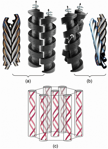
Figure 18. (Colour online) Structure of the Twist Grain Boundary phase, (a) showing the spiralling structure composed of screw dislocations [Citation43,Citation44], (b) a model where the molecules are dynamically fluctuating with periodic liquid-like or soft regions of twist, and (c) proposed structure of a smectic A* phase of a chiral liquid crystal side chain polymer [Citation46,Citation47].
![Figure 18. (Colour online) Structure of the Twist Grain Boundary phase, (a) showing the spiralling structure composed of screw dislocations [Citation43,Citation44], (b) a model where the molecules are dynamically fluctuating with periodic liquid-like or soft regions of twist, and (c) proposed structure of a smectic A* phase of a chiral liquid crystal side chain polymer [Citation46,Citation47].](/cms/asset/14add32c-1a65-4b92-aee3-e48b58d378dd/tlct_a_2002445_f0018_c.jpg)
For larger molecular materials, such as cholesteryl-substituted polymethylmethacrylate side-chain polymers, it has been reported that twisted smectic A* phases have been realised [Citation46,Citation47]. A proposed structure for the SmA* phase is shown in ), where the twist is parallel to the layering and the polymer backbone coils between the layers. For such systems, it is difficult to see how screw dislocations arranged into regular patterns to form grain boundaries is possible without the structure allowing for some form of flow or defect formation. Thus, this type of material is presumably similar in structure and properties to the model shown in ).
So what do we see with POM? Firstly, a mosaic texture is seen when a sample of 14P1M7 is sandwiched between cover-slip and microscope slide, see ). This pattern appears similar to that of a crystal B phase. In addition there are also extinct regions, which indicate that the phase is uniaxial with a potential hexagonal supermolecular arrangement, that is, not rectangular. Around the edges of the cover-slip and slide, where the material is uncovered, filamentary structures are seen, as shown in the colour inverted ). Some of the filaments are organised into curved arrangements similar to those sometimes seen for columnar phases. Curved growth can drive the motions of droplets, which was spectacularly demonstrated for a TGB droplet suspended on a free-standing film of a smectic A* phase as shown in ). At temperatures near to the phase transition the TGB droplet started to spin very rapidly as shown by the time elapse photography where the motions of the filaments are smeared out with their growth driving the rotation of the drop. The curvature and direction of the filamentary growth may be due to molecular chirality or just simply the curvature of the droplet. However, it indicates that the organisation of the TGB phase within the filaments is liquid-like enough to allow for curvature formation.
Figure 19. (Colour online) Polarised light optical microscopy for 14P1M7, (a) a mosaic texture sandwiched between slide and cover-slip, (b) the filamentary texture seen at the edges of the cover-slip (colour inverted), and (c) the self-propelled rotating texture of filaments located at the edge of a droplet, magnifications x100.
A structure for the filaments has been proposed by Gilli and Kamaye [Citation48], see , where the molecules are shown to be parallel to the fibre axis. Moving away laterally from the axis the arrangements of the molecules twist in a perpendicular direction as in ). The twist is moderated via the inclusion of screw dislocations, see ), where the defects are shown to be helically arranged.
Figure 20. Proposed structures of TGB filaments, (a) shows the molecular distribution inside a filament, and (b) shows the locations of screw deformations along the central axis of a filament [Citation48]. (c) Hexagonal packing of spiralling filaments. Figures (a) and (b) reproduced from reference [Citation48] with permission of Taylor and Francis.
![Figure 20. Proposed structures of TGB filaments, (a) shows the molecular distribution inside a filament, and (b) shows the locations of screw deformations along the central axis of a filament [Citation48]. (c) Hexagonal packing of spiralling filaments. Figures (a) and (b) reproduced from reference [Citation48] with permission of Taylor and Francis.](/cms/asset/00aef3c0-3a84-4bdd-a9ec-3af4ec3c41f7/tlct_a_2002445_f0020_b.gif)
Alternatively, the filaments may be spiralling fibres composed of bundles of helices being parallel to the filamentary axis, as shown in the model in ). As shown, close to the filamentary axis the helical arrangements are near parallel to the axis, but as nucleation occurs and growth lateral to the filament results on cooling at the transition the helices will tilt over as shown resulting in a larger helical structure being produced, somewhat like a superhelix (rope). In this model, local bundles of helices will fill space to give cylinders, which can pack together in a hexagonal array. Although not made-up of disc-like molecules, the structure would still be columnar even though composed of rod-like entities, and therefore should be classified as Colh.
For a variety of optically active tolanes the columnar nature of the TGBA phase was investigated by Ribeiro et al. [Citation49] one example is shown by compound 13 in . This material was found to exhibit a filamentary defect texture in agreement with the original TGBA compound 14P1M7, and a mosaic texture similar to that exhibited by columnar phases. The results obtained from X-ray diffraction showed that the phase was typical of a disordered smectic modification, and with a d spacing of 45.3 Å being slightly shorter than the calculated molecular length, consistent with the presence of a TGBA modification. However, as the mosaic texture was also observed, Ribeiro et al concluded that columnar ordering must also be present, and therefore a new model of the phase had to proposed to take this into account.
) was proposed to resolve the conflicting observations. Firstly, a basic arrangement was presented upon which to build the overall structure; it consisted of two adjacent smectic slabs separated by a grain boundary with an angle of α between the two slabs. For this architecture, the presence of common areas between two adjacent slabs are marked with dots to show the places where the smectic layers go continuously from one slab to the next, see ) The interfaces between the slabs were predicted to form twisted ribbons of molecules. As the 2D columnar ordering was known to exist in the grain boundaries, it was assumed that the columns were interrupted and then merged back into the smectic layers. However, as the lateral dimensions are fixed, the columns would have a constant density, and so it was possible to track them from one boundary to the next. This ensures the formation of domains of structures made of continuous columns/ribbons as shown in the figure.
Figure 21. Grain boundary between two adjacent smectic slabs. The helical structure shows the smectic slabs and the grain boundaries pointing down the page in (a), and across the page coming to the viewer in (b). The array of equidistant screw dislocations, shown as dots, arranges the smectic layers into ribbons or columns in a direction perpendicular to the figure for two smectic slabs (c).
Columnar phases based on fibre packing or on ribbon formation between SmA slabs are very different to how we might imagine typical columnar phases based on the packing of disc-shaped molecules. Either way, the columns are seemingly spiral structures, which when self-organised do so via self-assembled helical ribbons or fibres. The formation and identity of the columnar structuring of TGB phases therefore is dependent on supermolecular self-organisation followed by macromolecular self-assembly. Conversely, the nanostructuring of the TGB phase composed of layers is related to polymorphism of the smectic A phase. As a result, the TGB phase can appear as both columnar or smectic and is Janus depending on the conditions of its formation – thermodynamic or kinetic coupled with molecular dynamics and rate of change in temperature.
The chiral smectic A* phase was shown to be one of a member of polymorphic forms of twist grain boundary phases. We now report on compound 14 shown in , which exhibits a smectic C* variation known as the TGBC phase. Since the discovery of this phase there have been a number of other examples found, including the TGBC, TGBC*, TGBCcomm, TGBCincomm, and TGBCA phases [Citation50–55] Unlike antiphases where incommensurability is associated with differences in the in-plane modulations, for the TGB phases the incommensurability is related to differences in the repeat of the helical twist as a function of the pitch. Thus, when the angle α between the smectic slabs is a factor of 360° the phase is said to be commensurate and when it is not it is incommensurate. If the TGB phase has two wave modulations that make up its helical form, and they are out of phase by a repeat based on α that does not subdivide 360° they are incommensurate. For repeats that subdivide 360° they are commensurate.
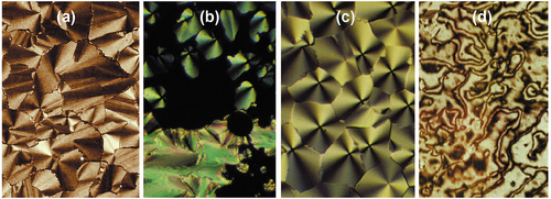
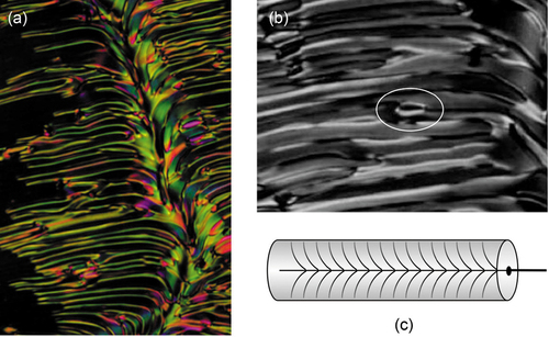
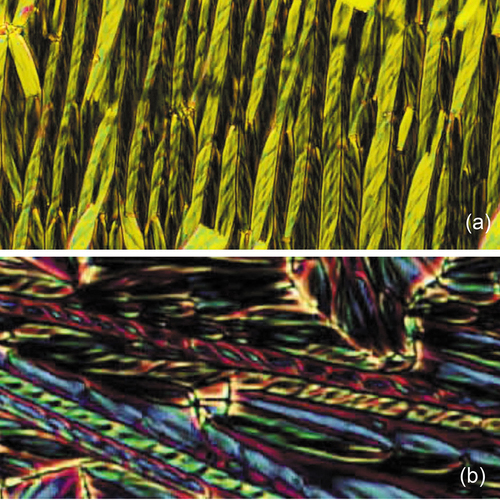
Three TGBC textures are shown in to c), the first (a) shows a fan texture which looks very similar to that of a conventional smectic A phase, except it is not focal-conic as no elliptical and hyperbolic lines of optical discontinuity are seen [Citation18]. The second photomicrograph (b) shows a texture typical of that exhibited by a columnar phase, where it’s strong birefringence may be a result of the local tilting of the molecules. These textures again support the concept of a mesophase appearing to exhibit two different phases but being associated with just a TGB phase. The third texture (c) is made up of bifurcated filaments that are different to those formed by other TGB phases, but may be related to commensurability. However, texture (b) indicates that the TGB and columnar phases are related to one another as Janus mesophases.
Figure 22. The fan-like texture of the TGBC phase (a), the mosaic defect texture of the columnar aspect of the TGBC phase (b), the unusual growth of filaments on the edges of a droplet of a TGBC phase (c), for compound 14 (x100).
Discovered at the Raman Institute, it was shown that it was possible for the TGBC phase to have a helical structure perpendicular to the layers within the smectic blocks (called TGBC*), and in addition the blocks can have 3D undulations forming a square grid. This phase was called the UTGBC* phase, which is characterised by having helical axes along the normal to the SmC* and parallel to the layer planes [Citation56]. The 2D lattice that is formed causes undulations to occur in the filamentary structure, where each filament has a width of approximately p/2 where p is the pitch in the TGB phase. Square patterns of disclinations are also formed in the Grandjean plane texture of the phase corresponding to the square grid. Thus, the UTGB phase is capable of showing defect textures associated with columnar or rectangular phases when observed at an angle.
So where a helix is effectively formed by two wave modulations, which are displaced from one another in 2D, supermolecular helices are generated. In the case of the 3D modulated UTGB phase, the square grid can support modulated columnar and lamellar phases occuring together in a Janus structural modes.
3.2 Twist bend and other phases
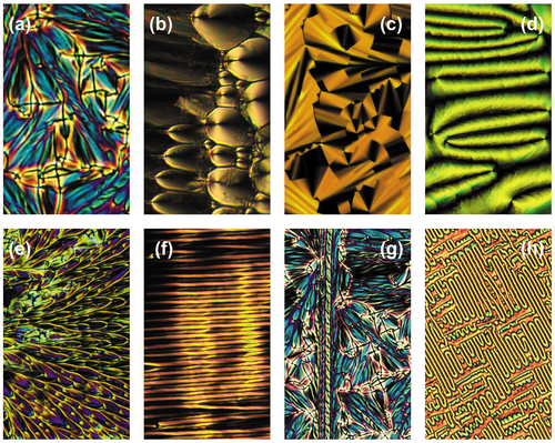
The twist bend phase, sometimes called the twist bend nematic phase (NTB) exhibits a miriad of different defect textures associated with a variety of mesophases. Many textures are based on lamellar phases, some on columnar, and filamentary, and a few are novel. shows a number of photomicrographs exhibited by dimers based on materials such as 1,11-di-(1”-cyanobiphenyl-4-yl)undecane. Picture 23(a) shows the focal-conic texture possessing hyperbolic and elliptical black crosses of optical discontinuity, typical of a smectic A phase. Texture (b) shows a defect pattern composed of parabolic defect lines at right angles to one another, again typical of the smectic A phase but not chiral nematic or hexatic phases. Pattern (c) is a paramorphotic focal-conic texture where there are no crosses of optical discontinuity, but there are dark steps corresponding to long-range ordering indicating that the phase may be of a soft crystal smectic phase type. Picture 4 shows the paramorphotic texture of a schlieren pattern derived on cooling from what was a nematic phase indicating the NTB phase is probably not nematic. Pattern (e) shows a splay of ellipsoids often exhibited by bent-core/banana (B) phases. The striped texture of (f) is associated with splay defects possibly associated with a Ns phase. Texture (g) possesses novel filamentary defects associated with left- and right-handed helices. And lastly, (h) appears as a novel defect pattern for a liquid crystal phase that is more likely to be associated with a polymer (but on a much larger scale). Although discovered a number of years ago [Citation57–59], and because as the variety of POM defect patterns is large, only recently was the twist bend nematic phase (NTB) given its name from structural studies.
Figure 23. (Colour online) Various defect patterns exhibited by the NTB phase; (a) focal-conic, (b) parabolic, (c) stepped fans, (d) paramorphotic schlieren, (e) splayed parabolics, (f) rows of filaments, (g) spiral filaments, (h) polymer-like fibres, (x100).
If we examine one of the novel textures shown in it can give us further insight into the structure of the twist bend phase. ) is a filamentary defect, much like the filamentary textures of the twist and splay defects shown for the TGB and Ns phases. The filaments for the twist bend phase have helical structures which tend to come in pairs where the filaments are packed together in left- and right-handed screws as shown in ). shows two larger photomicrographs (a) and (d) exhibiting filaments (or fibres) that have grown lineraly across the preparation, where the fibres are either helical or twisted ribbons. Texture (a) show rows of filaments of opposing twists meshing together, whereas (b) shows some filaments that appear to have double twist structures where the filaments might be composed of two helices or twisted ribbons. The double twists are akin to double twists in liquid crystalline DNA fibres which can self-assemble to form hexagonal columnar structures.
Figure 24. (Colour online) Top, rows of helical fibres alternating in left- and right-hand helical forms (a); bottom, a double helix shown in red (b), (x100).
The top of shows the filamentary texture of CB11CB (16 in ) where adjacent filaments have either left-handed or right-handed twists in an alternating pattern, that is, ….left-right-left-right … etc. This is possible because the material itself is achiral and so there will be an equal number of left- and right-handed helices produced upon cooling the sample in order to maintain net zero chirality. Thus, in the filaments the dimer molecules wrap themselves around the central heli-axis, as shown in ),
Figure 25. (Colour online) Chemical structures of CB11CB, 16, and CA23, 17 [Citation60], at the top of the figure, (a) shows how the molecules (in red and green) wrap around an axis to give a single helix, and (b) shows the structure of a double helix.
![Figure 25. (Colour online) Chemical structures of CB11CB, 16, and CA23, 17 [Citation60], at the top of the figure, (a) shows how the molecules (in red and green) wrap around an axis to give a single helix, and (b) shows the structure of a double helix.](/cms/asset/e0137278-80e0-4db1-92cf-76241afe0e51/tlct_a_2002445_f0025_oc.jpg)
Figure 26. (Colour online) Left- and right handed helices packing together, (a) right- hand packing with left-hand, and (b) packing together of the same hands causes a lateral twist. The structure of a hexagonal phase composed of double helices.
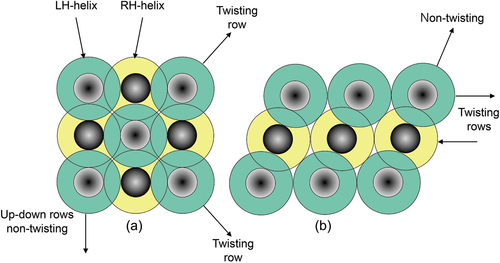
In 2D space the helices can be packed in either hexagonal or c-centred square planar arrays as shown in . In the square arrangement, the vertical and horizontal views of the helices (shown on the page) have alternating right- and left-handed helices, which are stable and won’t have any in-plane twisting between the helices. Diagonally across the lattice the helices will have the same handedness, and therefore there will be a tendency to have lateral twisting as shown in ). For the hexagonal array all of the horizontal rows of helices with the same handedness will experience lateral disruptive twisting, whereas the diagonal rows will have right-hand-left-hand packing, etc., and therefore will be stable. Measurements of the distances between the helical axes indicate that the square lattice is the slightly more stable arrangement depending on the dimensions of the molecules.
Figure 27. (Colour online) Packing of helices together, (a) shows a rectangular arrangement of the helices, and (b) a hexagonally close-packed structure. Where the tops of the helices have the same colour the packing will become twisted in the plane of the page. For opposing colours the packing will not have the same defects or lateral twists.
The lower part of on the other hand shows filamentary defects for a mixture of CB11CB with 20 wt% of CA23 (see chemical structures in ). One particular filament is shown in red. When this helical structure is examined, it appears to be either a double helix or a twisted ribbon, as shown in the schematic in ). Unlike the single twist system, the double twist appears to be more cylindrical in shape, and packing together of filaments of this type will not be affected by the packing as shown comparatively in . Consequently, the best close-packing arrangement for what are effectively cylinders is hexagonal, as shown in ) for double helices. Such structures are exhibited by other liquid crystals, for example, DNA. In concentrated solution, DNA is reported to exhibit a columnar phase, however in terms of the formation of double-helical filaments and associated defect textures which are typical of the NTB, the modification exhibited by DNA might also be considered to be a twist bend nematic phase, and hence a Janus mesophase. Not only does DNA exhibit NTB defect textures, but so do other polymers such as poly-γ-benzy-L-glutamate (PBLG) and Xanthan gum (structures shown in )
Figure 28. Other materials that exhibit defect textures associated with NTB phases. Top shows polymers PBLG, and Xanthan gum, and the lower two 18 and 19, are bent-core materials.
Herein lies a conundrum, this liquid crystal behaviour might be shared, and the structures might be hexagonal but they certainly are not classical columnar in the context of mesophase classification. They are infact similar to helical rods or cylinders, self-assembled or not, being packed together. For dimers, they self-organise to give rods of lengths greater than 50 Å, whereas the polymer systems can be well in excess of hundreds of Å. For bent core molecular materials as described earlier there is also the possibility that they too will exhibit defect textures associated with the NTB phase. Although not fully investigated, molecules that have chemical structures based on classical bent core or banana-shaped atchitectures, such as the materials 18 and 19 shown in the lower part of (a and b) also exhibit some defect textures that are similar to those shown by dimers, again packing to form self-assembled and self-organising helical structures. Indeed, it may be important to realise that other phases such as the dark conglomerate phases are also likely to be composed of left- and right-handed helical domains.
4. Coexisting Janus phases
So far, all of the materials systems we have examined have one distinct compound that exhibits more than one mesophase type at the same temperature and pressure. It appears that such materials actually have one mesophase structure, but when observed from multiple viewpoints it appears to have multiple corresponding phases. The most common combination is for a material to have a rod-like molecular architecture and to be identified as lamellar and/or columnar. These phase identifications are Janus forms of one mesophase structure. Much of course depends on the techniques used in the identification process, and it would be wise to use a number, that is, X-ray microscopy, calorimetry, etc., and also to be sure that these techniques are evaluating bulk mesophase structure, and not structures that are dependent on experimental substrates or constraints.
In the last example, we now examine individual liquid crystal materials and the phases that they exhibit, but this time where structurally different phases coexist at the same temperature and pressure, that is, they are genuinely different phases with different structures, and not the same mesophase observed at different angles with different techniques. We start first with an example of a material that exhibits this behaviour. The material, 2-{4-[(R)-2-fluorohexyloxy]phenyl}-5-{4-[(S)-2-fluoro-2-methyldecanoyloxy]phenyl}pyrimidine, 20, has been reported in the literature, and we have examined it’s behaviour many times again using POM, and we note in this report, none of the experiments were absolutely reproducible even though the material was pure and the same equipment was used each time. Thus, the following the results are the closest obtained to being reproducible.
4.1 Cubic phases and smectic liquid crystals
The structure of compound 20 is shown in . It is chiral and has two stereogenic centres, with R and S absolute configurations, associated with lateral fluorination in the terminal chains where the figure shows their positions relative to one another. The material exhibits a cubic phase, reported to have an Im3m structure [Citation62] which is present upon heating to the amorphous liquid that occurs at a temperature of 126°C. But on cooling the cubic phase does not necessarily appear again, and instead a chiral smectic C* phase forms from the liquid at a temperature of 117°C. Subsequently, an isotropic (cubic) phase forms at a lower temperature of 107°C. This phase sequence is given in the figure as reported by Hori et al. [Citation63].
Figure 29. (Colour online) Structure and the mesophase behaviour (°C) of 2-{4-[(R)-2-fluorohexyloxy]phenyl}-5-{4-[(S)-2-fluoro-2-methyldecanoyloxy]phenyl}pyrimidine 20 [Citation63]. The minimised geometry was optimised using ChemDraw 3D.
![Figure 29. (Colour online) Structure and the mesophase behaviour (°C) of 2-{4-[(R)-2-fluorohexyloxy]phenyl}-5-{4-[(S)-2-fluoro-2-methyldecanoyloxy]phenyl}pyrimidine 20 [Citation63]. The minimised geometry was optimised using ChemDraw 3D.](/cms/asset/236b970e-9ede-4636-bece-a0def4674efc/tlct_a_2002445_f0029_oc.jpg)
In our own studies, the clearing point was found to be 129.2°C, and as shown previously there is no direct transition back to the cubic phase, and instead supercooling occurs, which might be expected for a recrystallisation back to a solid. However, the subsequent transitions can become quite entertaining, as different phases will appear depending on how the sample is treated. If a specimen is undisturbed and just cooled directly from the liquid at a rate of approximately 5 to 10°C min−1 a transition back to the isotropic (cubic) phase can be observed to occur at a variety of temperatures (even under the same conditions). Alternatively, if the cover-slip of the sample is disturbed and the sample is held at around 111 ± 4°C a chiral smectic phase appears, which has been reported as SmX or SmC*. On further cooling, this phase can return to an isotropic (cubic) phase or not (depending on the area of the sample viewed in the microscope). It is also important to note that these transitions occur at temperatures above the melting point of the thermodynamically stable solid produced via recrystallisation from the synthesised material. Variations of the phase behaviours (but not the full range that can be recorded simply) of the material are given in (top).
Figure 30. (Colour online) The defect textures (a to c) taken at a magnification x165 and phase behaviour (°C) of 2-{4-[(R)-2-fluorohexyloxy]phenyl}-5-{4-[(S)-2-fluoro-2-methyldecanoyloxy]phenyl}pyrimidine.
![Figure 30. (Colour online) The defect textures (a to c) taken at a magnification x165 and phase behaviour (°C) of 2-{4-[(R)-2-fluorohexyloxy]phenyl}-5-{4-[(S)-2-fluoro-2-methyldecanoyloxy]phenyl}pyrimidine.](/cms/asset/7a7a5457-4650-4d05-9997-f5dbda026db5/tlct_a_2002445_f0030_oc.jpg)
Examining the defect textures of the smectic phase(s) of 20 we also find a range of behaviours, as shown in . When the sample cover-slip is disturbed in the isotropic liquid to give a bulk preparation with accompanying droplets (both sandwiched between cover-slip and slide) we can observe focal-conic and Grandjean planar textures together in a droplet as shown in ). The colour of the plane texture and the lines in the focal-conic defects indicate the structure of the phase is helical. ) shows a schlieren texture occurring in a droplet of another area of the specimen. It flows more like a nematic phase at the transition than a smectic. Thirdly, the bulk specimen exhibits focal-conic domains with line defects, which form at the phase transition, as shown in ). This defect pattern has not been observed before, and could not usually be obtained either for this material. It also should be noted that these textures are not necessarily stable at the same time and temperature, and may occur in the presence of an isotropic phase.
There is a possible explanation for these contrasting results, which is related to crystallisation. Normally for most materials, when a material is synthesised it is recrystallised to obtain the purest form and the most stable crystal phase, from which a reproducible melting point can be obtained. On cooling from the liquid state nearly all materials will show supercooling back to the solid where the recrystallisation process is affected by kinetic processes, and therefore this process is not reversible nor is the temperature necessarily the same. For compound 20, it appears that there is inconsistency in the temperature at which the cubic phase returns, suggesting that this is a kinetic process and therefore dependent on cooling rate, mechanical disturbance etc. And yet the temperatures at which the cubic phase returns on cooling are higher than the reproducible melting point of compound 20. This realisation provides another conundrum, is the cubic phase a crystal or not? For compound 20, the cubic phase has a reproducible melting point, which is equivalent to the clearing point, but the recrystallisation shows supercooling and is not reproducible. However, the molecules within the structure of the cubic phase are disordered without periodicity, but yet they have local orientational order. The only lattice-like periodic order for the cubic phase is associated with the defects, which appear to impart crystalline properties on the cubic phase, leading one to conclude that cubic phase of compound 20 is a defect stabilised crystal. The other phases that appear in the temperature range of the supercooling of the cubic phase are monotropic liquid crystal phases, such as the smectic C phase, which exhibits a reproducible upper transition temperature. Thus it appears that materials such as compound 20 do not exhibit Janus properties, but instead exhibit unusual defect stabilised crystallinic behaviour.
The type of behaviour exhibited by compound 20 can also be observed for the long chain (C16 and C18) 4ʹ-alkoxyoxy-3ʹ-nitrobiphenyl-4-carboxylic acids, and the 4ʹ-alkoxyoxy-3ʹ-cyanobiphenyl-4-carboxylic acids, and for the lower homologues of the 1,2-bis-(4-n-alkoxybenzoyl)-hydrazines (C8 to C10) [Citation64].
5. Final remarks
This article is intended to be part review, part new research, and part conceptual, and is designed to link a number of phases together through various forms of modulations. It also looks to highlight the contributions Professor Sadashiva has made in the area liquid crystal materials research.
There is no doubt there have been complications in the categorisation of bulk liquid crystal mesophases over the past years, most notably with the cataloguing of smectic phases composed of rod-like molecules [Citation65,Citation66]. Researchers were using POM, miscibility phase diagrams, DSC and X-ray and neutron diffraction to make their recommendations, and with resolution and agreement the issues of the time were resolved. With a few more additions and inputs the unified classification system for bulk smectic liquid crystals has endured up to this point. During the India–UK workshop bent core mesophases or molecules were at the height of interest, and Prof Sadashiva gave us a copy of his lecture on the subject. Distilling the understandings of the time for structure and categorisation we have produced an extract for known ‘bent-core’ mesophases, which is shown in [Citation24]. We see from this diagram that many phases are listed with the B code letter, some with columnar, and others are listed as smectic and one with nematic. There are also many sub-classes, for example, Bn where n is an integer presumably for the order in which the B phase was discovered. There are other sub-groups that refer to the molecular ordering, for example, tilt and reverse tilt, and some use ferroelectric notation.
Figure 31. Structures and categorisations of ‘bent-core liquid crystals’. This figure is adapted from a slide given to JWG by Professor Sadashiva from his lecture at York University [Citation24].
![Figure 31. Structures and categorisations of ‘bent-core liquid crystals’. This figure is adapted from a slide given to JWG by Professor Sadashiva from his lecture at York University [Citation24].](/cms/asset/b6216304-2f8c-4a13-b564-b7ac41fac85e/tlct_a_2002445_f0031_b.gif)
With the numbers of new phases increasing, along with their subdivisions, and unification difficult to achieve, may be looking for alternatives for mesophase classification might be necessary.
Dedication
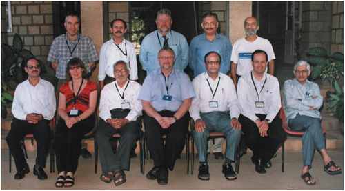
Known simply to us as BK, Professor Sadashiva was a very popular liquid crystallographer with the UK Liquid Crystal community. Indeed, Professor Duncan Bruce and I were very fortunate to lead a UK team in a visit to BK’s research home in Banagalore in 2005, see . Our visit, funded by the Royal Society of London, was to participate in an India–UK Science Network and to give presentations at a three-day Seminar Series entitled, ‘Recent Trends in Liquid Crystal Research’, at the Raman Institute in Bangalore on the 14–16 of November in 2005. A return Network meeting was held in the University of York on the 10 of July 2007. The meetings at the Raman Institute involved lectures, poster sessions and visits to the research laboratories, and most importantly delightful interactions with the young and enthusiastic scientists coming from a number of institutions. As you know Liquid Crystals is a unique and multidisciplinary subject, in that discoveries in physics, chemistry, biology, and engineering are often brought together under one roof where the transmission of ideas and concepts can move fluidly between the disciplines and researchers. Theories can be put into practice experimentally, visionary discoveries can be probed via theory, and in recent years many of these aspects of research are becoming bound by computation and simulation. This so too short a meeting had all of these aspects, and I don’t think the UK team ever forgot their trip to Bangalore, it meant a lot to them and we were grateful to BK for organizing the Network and the social interactions.
Plate 1. (Colour online) The India–UK Science Network: Three-day seminar on “Recent Trends in Liquid Crystal Science”. Left to Right (back row) Prof AN Cammidge, Dr Krishna Prasad, Prof DW Bruce, Dr Suresh Das, Prof Sriram Ramaswamy, and (front row) Prof Sandeep Kumar, Prof HF Gleeson, Prof VGKM Pisipati, Prof JW Goodby, Prof BK Sadashiva, Prof CT Imrie, and Prof NV Madhusudana.
As a chemist, I take great interest in all chemistry aspects of liquid crystals. In particular, what are (were) the contributions of chemistry to this multidisciplinary subject – why were certain compounds made, how were their molecular architectures designed, how were they synthesised, and how well were they characterized? Privately, while in Bangalore, I asked BK about the discovery of discotic liquid crystals, and I learned that like most chemists he wanted to make disc-like molecules and to see if they were liquid crystalline or not. This seemed to be the seed for the preparation of the hexa-alkanoyloxbenzoates and discotics. Although the targets were straight forward, and having done them myself, their preparations are not easy. Thus, I learned from BK his enthusiasm for making designer molecules, and I greatly appreciated this and his wide contributions to the field. This was emphasised later in York where he gave two masterful presentations on Banana liquid crystals (later called bent-core liquid crystals). We had quite a few discussions on the use of Banana and B phases – he smiled at my despair of the use of Banana and B as mesophase classifiers – after all we already had two B phases.
BK’s wide remit in the synthesis of liquid crystals is probably best summed up in the following two quotations, the first from a UK research report - Chemistry at The Centre: An International Assessment of University Research In Chemistry In The UK, 2009, Chemistry in Britain, November 1985, which identified; ‘One of the exciting opportunities for the future is to use synthesis to prepare molecules that are electronically, optically and perhaps magnetically functional … … ….the initial products of nanotechnology are nanostructured materials prepared by bottom-up synthesis’. And secondly, Professor Sir Jack Baldwin FRS of Oxford University had recognized earlier a similar range of possibilities when he noted that; ‘Chemistry has a strongly creative potential. It can create substances and materials never dreamed of before’. I suggest that BK’s research journey has been reflected in the meaning of Janus. Of beginnings, transitions, duality, doorways, and time, which allowed him too, ‘to create materials never dreamed of before’.
Rest in peace BK. John Goodby FRS, 19.07.21
Acknowledgments
The authors thank Drs Isabel Saez, John Moore, Laurence Abbott, Craig Archbold, Mike Hird, and Robert Lewis for their support and collaborations over the years. We are indebted to the EPSRC for its continued support of our research through the following grants, EP/J007714/1, EP/K039660/1 and EP/M020584/1. The authors also thank QinetiQ for funding an ICASE studentship for RJM, Dr I. Sage for useful discussions, and a special thank you to Professor A. Yoshizawa for a sample of 2-{4-[(R)-2-fluorohexyloxy]phenyl}-5-{4-[(S)-2-fluoro-2-methyldecanoyloxy]phenyl}pyrimidine.
Disclosure statement
No potential conflict of interest was reported by the author(s).
Additional information
Funding
References
- Chandrasekhar S, Ratna BR, Sadashiva BK, et al. A thermotropic biaxial nematic liquid crystal. Mol Cryst Liq Cryst. 1988;165:123–130.
- Praefcke K, Blunk D, Singer D, et al. Design of low-molar mass thermomesogens in the search for biaxial nematic liquid crystals. Mol Cryst Liq Cryst. 1998;323:231–259.
- Levelut AM. Structures of mesophases of disc-like molecules. J Chim Phys Phys-Chim Biol. 1983;80:149–162.
- Ohta K, Muroki H, Takagi A, et al. Discotic liquid crystals of transition metal complexes, 3: the first-established discotic lamellar phase in bis[1,3-di(p-n-alkoxyphenyl)propane-1,3-dionato]copper(II). Mol Cryst Liq Cryst. 1986;140:131–152.
- Sakashita H, Nishitani A, Sumiya Y, et al. X-ray diffraction study on discotic lamellar phase in bis(1,3-di(p-nalkoxyphenyl)propane-1,3-dionato)copper(II). Mol Cryst Liq Cryst. 1988;162:211–219.
- Ribiero AC, Martins AF, Giroud AM. Evidence of a smectic phase of disc-like molecules. Mol Cryst Liq Cryst Lett. 1988;5:133–139.
- Mori A, Yokoo M, Hshimoto M, et al. Lamellar columnar phase induced by rod-like 1,3-diazaazulene derivatives. Proc Jap Liq Cryst Conf. 2003:155-156, ibid. J Am Chem Soc. 2003;125:6620–6621.
- Saez IM, Goodby JW. Supermolecular liquid crystals. J Mater Chem. 2005;15:26–40.
- Saez IM, Goodby JW. Supermolecular liquid crystals. In: Mingos DMP, Kato T, editors. Liquid crystalline functional assemblies and their supramolecular structures, structure and bonding. Vol. 128. Berlin Heidelberg: Springer-Verlag; 2008. p. 1–62.
- Saez IM, Goodby JW. “Janus” supermolecular liquid crystals – giant molecules with hemispherical architectures. Chem Eur J. 2003;9:4869–4877.
- Saez IM, Goodby JW. Design and properties of Janus supermolecular liquid crystals. Chem Commun. 2003;1726–1727.
- Leadbetter AJ. Structural classification of liquid crystals. In: Gray GW, editor. Thermotropic liquid crystals, critical reports on applied chemistry. Vol. 20. Chichester: Wiley; 1987. p. 1–27.
- Sigaud G, Hardouin F, Achard MF, et al. A new type of smectic A phase with long range modulation in the layers. J Physique. 1981;42:107–1111.
- Levelut AM, Tarento RJ, Hardouin F, et al. Number of SmA phases. Phys Rev A. 1981;24:2180–2187.
- Hardouin F, Levelut AM, Sigaud G. A nomalies of periodicity in some liquid crystalline cyano derivatives. J Physique. 1981;42:71–77.
- Tinh N-H, Hardouin F, Destrade C, et al. New phase transitions SmC-SmC2 and SmAd-SmC2 in pure mesogens. J Physique Lett. 1982;43:739–744.
- Goodby JW, Walton CR. Antiphase behaviour in the 4-n-Alkoxybiphenylyl-4ʹ-cyanobenzoates (nOBCB’s). Mol Cryst Liq Cryst. 1985;122:219–239.
- Gray GW, Goodby JW. Smectic liquid crystals - textures and structures. Leonard Hill, Glasgow and London, 1984, 220.
- Hardouin F, Tinh N-H, Achard MF, et al. A new thermotropic smectic phase made of ribbons. J Physique Lett. 1982;43:327–331.
- Bradbury CK. Liquid crystals based on unusual molecular architecture. PhD thesis, University of York 2012.
- Szydlowska J, Mieczkowski J, Matraszek J, et al. Bent-core liquid crystals forming two- and three-dimensional modulated structures. Phys Rev E. 2003;67:031702.
- Takezoe H T, Takanishi Y. Bent-core liquid crystals: their mysterious and attractive World. Jpn J Appl Phys. 2006;45:597–625.
- Pelz K, Weissflog W, Beimeister U, et al. Various columnar phases formed by bent-core mesogens. Liq Cryst. 2003;30:1151–1158.
- Sadashiva BK. Liquid crystals of cent-core compounds. India-UK Science Network. Recent trends in liquid crystal research. Department of Chemistry, University of York UK. 2007 July.
- Umadevi S, Sadashiva BK, Shreenivasa Murthy HN, et al. Mesogenic dimers composed of bent-core molecules with flexible alkylene spacer. Soft Matter. 2006;2:210–214.
- Umadevi S, Sadashiva BK. Liquid crystalline properties and dependence of transition temperatures on the length of the flexible alkylene spacer of symmetric dimers composed of bent-core units. Liq Cryst. 2007;34:673–681.
- Dantlgraber G, Diele S, Tschierske C. The first liquid-crystalline dimers consisting of two banana-shaped mesogenic units: a new way for switching between ferroelectricity and antiferroelectricity with bent-core molecules. Chem Commun. 2002;2768–2769. doi:https://doi.org/10.1039/b209106b
- Kosata B, Tamba GM, Baumeister U, et al. Liquid crystal dimers composed of bent-core mesogenic units. Chem Mater. 2006;18:691–701.
- Mandle RJ. The nitro group in liquid crystals. PhD thesis, University of York 2012.
- Mandle RJ, Cowling SJ, Goodby JW. A nematic to nematic transformation exhibited by a rod-like liquid crystal. Phys Chem Chem Phys. 2017;19:11429–11435.
- Mandle RJ, Cowling SJ, Goodby JW. Rational design of rod-like liquid crystals exhibiting two nematic phases. Chem Eur J. 2017;23:14554–14562.
- Mandle RJ, Cowling SJ, Goodby JW. Structural variants of RM734 in the design of splay nematic materials. ChemRxiv. 2021. doi:https://doi.org/10.26434/chemrxiv.14269916;
- Goodby JW. Nano-objects - sculpting and shape in molecular material design. Liq Cryst. 2019;46:1901–1924.
- Mandle RJ, Cowling SJ, Goodby JW. Structural variants of RM734 in the design of splay nematic materials. Liq Cryst. 2021. doi:https://doi.org/10.1080/02678292.2021.1934740
- Mertelj A, Cmok L, Sebastián N, et al. Splay nematic phase. Phys Rev. X. 2018;8(1–12):041025.
- Pleiner H, Brand HR. Spontaneous splay phases in polar nematic liquid-crystals. Europhys Lett. 1989;9:243–249.
- Chen X, Korblova E, Glaser MA, et al. Polar in-plane surface orientation of a ferroelectric nematic liquid crystal: polar monodomains and twisted state electro-optics. Proc Nat Acad Sci. 2021 Jun;118(22):e2104092118.
- Sebastián N, Mandle RJ, Petelin A, et al. Electrooptics of mm-scale polar domains in the ferroelectric nematic phase. Liq Cryst. 2021;1–17. doi:https://doi.org/10.1080/02678292.2021.1955417
- Saha R, Nepal P, Feng C, et al. Multiple ferroelectric nematic phases of a highly polar liquid crystal compound. 2021 April 1. Available from: https://ui.adsabs.harvard.edu/abs/2021arXiv210406520S
- Cladis PE, Brand HR. Hedgehog-antihedgehog pair annihilation to a static soliton. Phys A. 2003;326:322–332.
- Cowling SJ, Davis EJ, Mandle RJ, et al. Defect textures of liquid crystals. In: Kwok H-S, Naemura S, Ong HL, editors. Progress in liquid crystal science and technology. Vol. 4. Singapore: World Scientific, series in Liquid Crystals; 2013. p. 49–79.
- Goodby JW, Waugh MA, Stein SM, et al. Characterization of a new helical smectic liquid crystal. Nature. 1989;337:449–452.
- Renn SR, Lubensky TC. Abrikosov dislocation lattice in a model of the cholesteric to smectic A transition. Phys Rev A. 1988;38:2132–2147.
- Goodby JW. Twist grain boundary (TGB) phases. In: Mingos DMP, editor. Structure and bonding - liquid crystals II. Vol. 95. Berlin Heidelberg: Springer, Verlag; 1999. p. 83–147.
- Goodby JW. Photograph of sculpter by Tony Cragg at Exhibition Road, London. 25 August, 2012.
- Freidzon Y, Kharitonov AV, Shibaev VP, et al. Thermotropic liquid crystalline polymers – 19. Peculiarities of the liquid crystalline structure of cholesterol-containing polymers. Eur Polym J. 1985;21:211–216.
- Freidzon Y, Tropsha Y, Tsukruk VV, et al. Features of layer orderliness of cholesterol-containing polymers. Polym Sci (USSR). 1987;29:1505–1511.
- Gilli JM, Kamayé M. Smectic A-cholesteric transition in a side chain cooligomer-DCE1 blend. A particular confined geometry for the TGB phase? Liq Cryst. 1992;12:545–560.
- Ribeiro AC, Dreyer A, Oswald L, et al. Columnar and smectic ordering in a TGB A phase. J Phys II (Paris). 1994;4:407–412.
- Anakkar A, Daoudi A, Buisine J, et al. First observation of a SmC*- SmA-TGB multicritical point in a pure compound. J Teherm Anal. 1994;41:1501–1513.
- Petit M, Barois P, Nguyen HT. Structural study of the smectic-C twist grain boundary phase (TGBC) under external electric field. J Phys II (Paris). 1996;36:185–190.
- Navailles L, Barois P, Nguyen HT. X-ray measurement of the twist grain boundary angle in the liquid crystal analog of the Abrikosov phase. Phys Rev Lett. 1993;71:545.
- Navailles L, Pindak R, Barois P, et al. Structural Study of the Smectic-C twist grain boundary phase. Phys Rev Lett. 1995;74:5224.
- Isaert N, Navailles L, Barois P, et al. Optical evidence of the layered array of grain boundaries in TGBA and TGBC mesophases. J Phys II France. 1994;4:1501–1518.
- Meier JG, Nobili M, Carlsson T, et al. Possible model of an antiferroelectric twist grain boundary phase. Phys Rev E. 2007;76:011704.
- Pramod PA, Madhusudana PR. A three-dimensionally modulated structure in a chiral smectic C liquid crystal. Current Sci. 1997;73:761–765.
- Ungar G, Percec V, Zuber M. Liquid-crystalline polyethers based on conformational isomerism .20. nematic nematic transition in polyethers and copolyethers based on 1-(4-hydroxyphenyl)-2-(2-R-4-hydroxyphenyl)ethane with R = fluoro, chloro, and methyl and flexible spacers containing an odd number of methylene units. Macromolecules. 1992;25:75–80.
- Tripathi CSP, Losada-Pérez P, Glorieux C, et al. Nematic-nematic phase transition in the liquid crystal dimer CBC9CB and its mixtures with 5CB: a high-resolution adiabatic scanning calorimetric study. J Phys Rev. 2011;84:041707.
- Chen D, Porda JH, Hooper JB, et al. Chiral heliconical ground state of nanoscale pitch in a nematic liquid crystal of achiral molecular dimers. Proc Natl Acad Sci USA. 2013;110:15931–15936.
- Archbold CT, Davis EJ, Mandle RJ, et al. Goodby JW. Chiral dopants and the twist-Bend nematic phase – induction of novel mesomorphic behaviour in an apolar bimesogen. Soft Matter. 2015;11:7547–7557.
- Mandle RJ, Stevens MP, Goodby JW. Developments in liquid-crystalline dimers and oligomers. Liq Cryst. 2017;44:2046–2059.
- Matsunaga Y, Hori K, Yoshizawa A, et al. Chiral recognition in the crystal structure of a dichiral mesogen with a unique isotropic mesophase: 2-{4-[(R)-2-fluorohexyloxy]phenyl}-5-{4-[(S)-2-fluoro-2-methyldecanoyloxy]phenyl}pyrimidine. Liq Cryst. 2001;28:1805–1812.
- Hori K, Matsunaga Y, Yoshizawa A, et al. Diversity in the packing modes of mesogenic diphenylpyrimidines with two chiral centres in their crystal structures: the role of interactions between the pyrimidine rings. Liq Cryst. 2004;31:759–766.
- Demus D, Gloza A, Hartung H, et al. New thermotropic cubic mesophases. Krist Res und Techn. 1981;16:1445–1451.
- Demus D, Goodby JW, Gray GW, et al. Recommendations for the use of the code letters G and H for smectic phases. 1980;Mol Cryst Liq Cryst Lett. 56:311–314.
- De Vries A, Ekachai A, Spielberg N. Why the molecules are tilted in all smectic A phases, and how the layer thickness can be used to measure orientational disorder. Mol Cryst Liq Cryst. 1979;49:143–152.