
INTRODUCTION
One of the key strategies exemplifying the conservation approach to vertebrate fossil preparation is the clamshell storage jacket. Various iterations of clamshell jackets have been designed and built over the last three decades (Chaney, Citation1992; Fitzgerald et al., Citation1992), and in 2006, Jabo et al. tried to standardize archival methods and materials to create these storage jackets. However, since the publication of Jabo et al. (Citation2006) many advances have been made in this technique. These innovations originated at the National Museum of Natural History (NMNH) and were expanded upon at other institutions by preparators who were trained by the NMNH. Many workshops demonstrating these techniques have been presented internationally, helping other institutions improve the conservation and storage conditions in their vertebrate fossil collections. Many of the advances relate to the materials, methods, and processes used to create liners for the jackets and extend to design and internal support structures as well. The discussion of these new innovations begins with an overview of the basic concepts and advantages of clamshell storage jackets, followed by the step-by-step instructions needed to create these innovative fossil storage systems.
CONCEPTUAL OVERVIEW
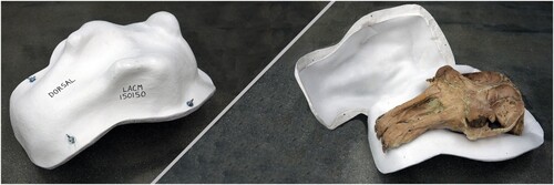
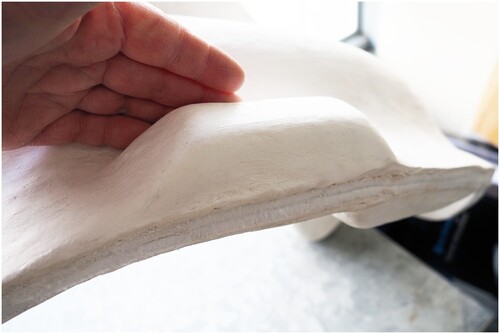
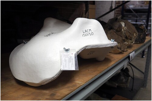
Clamshell storage jackets are so called because they are comprised of two halves which enclose a specimen much the way a violin case encloses the instrument. Like the violin case, the clamshell jacket is form-fit to the specimen to protect and support it. Unlike a violin case, the clamshell jacket is designed to be opened resting on either half, allowing the jacket to be flipped and either side of the specimen—usually dorsal or ventral—to be examined without ever entirely leaving this container ().
FIGURE 1. A closed and opened clamshell storage jacket for the skull of LACM 150150, the type specimen of the desmostylian Neoparadoxia cecilialina, at the Natural History Museum of Los Angeles County (LACM).
The basic principles of the clamshell storage jacket are:
- Two halves that together completely enclose the specimen.
- A rigid outer shell.
- An inner liner of soft, inert material for padding.
Other features can include feet to stabilize the jacket at rest, handles to aid manipulation, and additional structures to increase rigidity or support. The advantages of these jackets are:
- Uniformly supports and pads the specimen to prevent breakage.
- Shields the specimen from dust, moisture, pests, and collisions.
- Mitigates stresses of sudden changes in ambient temperature and humidity.
- Reduces handling (which accounts for most specimen damage).
- Offers additional protection during shipping.
- Allows CT scanning in-jacket (when metal-free).
- Made to last centuries from archival-grade materials harmless to specimens.
Liners
As new materials become available, and practitioners explore new methodologies, procedures and techniques will necessarily evolve. Over the three decades that clamshell storage jackets have been in use, preparators have contributed fresh strategies and insights. Innovations tend to be variations on a theme, and this is true with clamshell storage jackets. This paper does not seek to be the final word on the subject, but rather a report on the state-of-the-art as of this writing.
In earlier methodologies (Jabo et al., Citation2006) a sheet of clay was used as a temporary spacer for a liner that would be installed after construction of the jacket shell. In current practice a liner is tailored to the specimen first, then the shell built upon it. There are currently three liner options in wide use:
6 mm polyester felt.
6 mm polyethylene foam.
3 mm polyethylene foam.
Each of these materials presents minor advantages and disadvantages, and slight variations in process, but all are regarded as acceptable, archival grade materials.
Polyester felt is typically used at a 6 mm thickness and a density of 814 g/m². The 6 mm thickness is soft, readily cut, and seams are easily sewn, taped or hot-glued together. It conforms especially well to the specimen under the weight of wet plaster and fiberglass, but requires extra vigilance to make sure undercuts are filled so the jacket does not lock onto the specimen. One drawback is the felt fibers can snag on rough parts of the specimen resulting in damage to both specimen and liner. The felt can also be soiled by retained matrix, so this choice is best for smooth, clean, and well consolidated fossils. It is also possible for wet plaster to seep through the felt during construction and form hard patches in the liner. This effect can be mitigated by practice and pulverizing the patches with a blunt tool.
The two other liner options are different thicknesses of polyethylene foam, often referred to as poly-foam or the brand name Ethafoam. Plaster will not seep through poly-foam (it can leak in a bit at seams, but is easily removed), and it is easily cleaned. Seamlines can be sewn, taped, hot-glued or welded, and extra internal padding or appliances are easily added to the basic liner. It is stiffer than felt and so does not conform tightly to the specimen, which makes it slightly more forgiving of undercuts. The two thicknesses cited entail differences in methodology. The 3 mm foam is more pliant and, like felt, conforms to the specimen under the weight of the wet plaster and fiberglass alone. This allows the shell to be constructed in a single plastering session. The 6 mm foam is stiffer and requires two separate applications of plaster, a process detailed later. Thus, the 3 mm is the least problematic liner material, but is only suitable for smaller, lighter specimens.
Materials Used in Jacket Construction
– A sandbox at least 1.5 times as large as your specimen, with sand deep enough to immerse it halfway. If the specimen is very heavy or larger than your sandbox, you can construct a scaffolding around it with materials such as wood blocks, cardboard, foam core, and hot melt glue.
– Consolidant, such as ethyl methacrylate copolymer (Paraloid B-72) or polyvinyl butyral (Butvar B-76) dissolved in acetone or ethanol. Butvar B-76 in a 10% w/v solution in acetone was used in the demonstration pictured.
– Plastic wrap and plastic sheeting, such as heavy-gauge trash bags.
– Plaster, a hard, fine-grained, long-setting gypsum cement such as USG Hydrocal FGR-95 (an architectural plaster used in the following demonstration) is ideal. Other gypsum cements and dental plasters will have sufficient hardness, but may have shorter work times. Plaster of Paris and moulding plaster are not sufficiently durable for this purpose.
– Fiberglass cloth (10 or 15 mil surfacing veil, or woven cloth) cut into panels and strips. Fiberglass cloth comes in a variety of styles and thicknesses. Chopped and woven fiberglass cloths will be thicker and therefore require proportionally fewer layers during construction. Any woven cloth should have a loose weave to allow plaster to penetrate and impregnate the cloth. A 10 mil single-strand surfacing veil was used in the following demonstration.
– 6 mm or 3 mm thick medium density polyethylene foam, or 6 mm polyester felt. A 6 mm polyethylene foam was used in the following demonstration.
– 25 mm or 50 mm polyethylene plank foam.
– A large gauge sewing needle and polyester thread.
– Hot melt adhesive (aka hot glue) and glue gun.
– A heat gun.
– Medium-firmness, sulfur-free, non-hardening modeling clay, such as Van Aken Plastalina (“clay”).
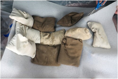
– Sand bags of varying size and weight.
– Archival, pigment-based felt-tipped marker, such as a 3 mm-nib PITT graphic pen.
– 4 mil locking plastic bags.
– 12 L plastic tubs for mixing plaster.
– Power drill with a 6 mm bit.
– Reciprocating or oscillating saw with fine tooth blade, or angle grinder.
– Appropriately sized steel machine screws or hex bolts (“bolts”), washers, and wing nuts for the size and thickness of the jacket, i.e., four 35 mm long bolts, eight 25 mm washers, and four wing nuts for a 1-meter-long jacket.
– Various: paint brushes, pencils, pens, utility knives, sandpaper, wire brushes as needed.
– Personal Protective Equipment (PPE): N-95 or equivalent respirators, HEPA dust extractor, eye and hearing protection, latex, vinyl, or nitrile gloves, and lab coat.
A materials supplier list for the United States, current as of this publication, can be found in the Supplementary Files. Specialty materials suppliers are liable to change, and some companies may not be available in all areas, so always check with local suppliers for these materials.
METHODOLOGY
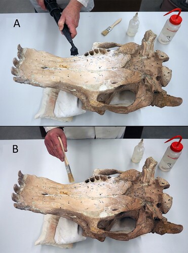
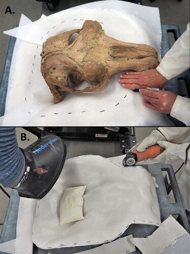
Step 1—The first step remains the cleaning and conservation of the fossil. During this process the specimen may be evaluated for jacketing issues. Based on the shape, weight, condition, and surface texture of the specimen, determine what would be the best liner material of the options on hand ().
FIGURE 2. LACM 150150 being A, cleaned and B, conserved before the jacketing process begins.
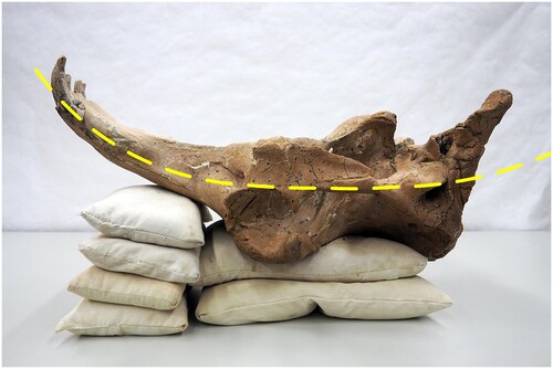
Step 2—The second step is determining the midline where the two sides of the jacket will meet. This line may undulate gently, usually following the widest point in the specimen’s profile and as close to the center of the specimen’s thickness as possible. Both halves of the jacket should be roughly equal, ideally. If one side of the jacket is too deep it can inhibit the study, photography, or scanning of the specimen. Consider the surfaces that will best bear the weight of the specimen, the diagnostic elements (like teeth) that need to be exposed, as well as the size and weight of the jacket halves. The less complex the design of the jacket the better, as long as the specimen is supported. Try to ensure it does not have sharp or complicated peaks and ridges in it that make it difficult to build, or that can create areas of high contact pressure on the specimen. The padding does not have to contact every part of the specimen, but enough to safely support it and prevent the specimen from shifting when the jacket is moved ().
FIGURE 3. Midline of the LACM 150150 skull where the two sides of the clamshell will meet, based on the skull's morphology and robustness.
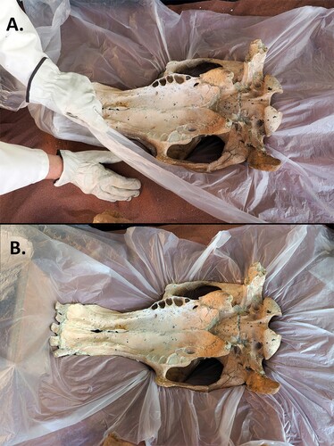
Step 3—Smooth the sand in the sandbox to create a level surface. Cover the sand in plastic sheeting. Excavate the sand so the specimen—atop the plastic sheeting—can be sunk up to its midline in a sandbox. Refine and smooth the sand surrounding the specimen so that a 75 mm-plus margin encircles the fossil level with the midline. In lieu of a sandbox, a scaffolding can be built around the specimen on a tabletop or floor using corrugated cardboard and wood, or foam core to form the surrounding margin, the pieces hot-glued or taped together. This margin will support the 50–75 mm wide flange of the jacket, perpendicular to the specimen ().
FIGURE 4. LACM 150150, A, being embedded in the sandbox to create the dividing line on the skull and, B, the margin leveled to support the flange.
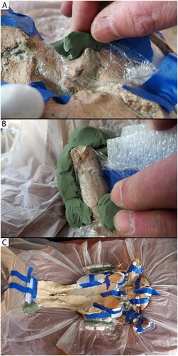
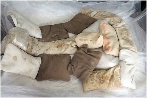
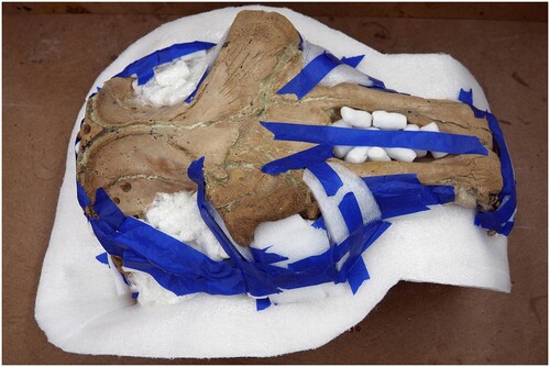
Step 4—Locate any undercuts, large gaps, or holes in the specimen into which the liner might intrude too deeply. An undercut is a space beneath any ridge or part of the specimen protruding parallel to the midline. Undercuts and large holes can be temporarily filled with many materials: foil, scrap foam, packing peanuts, damp paper towel, clay, or whatever is at hand. These fills might need to be strapped in place with low-tack painter’s tape. Beware of subtle undercuts, like at the fossil midline, where the jacket might lock onto the specimen. Voids can be created around fragile elements that should not contact the jacket liner, such as delicate processes, or teeth. This can be accomplished by wrapping these parts with some sort of spacer material such as pieces of foam or clay. Whenever using clay, avoid bringing it into direct contact with the specimen by wrapping that part in plastic film first ().
FIGURE 5. Creating voids, A, around a delicate process and, B, around a tooth using clay; C, fragile parts of the skull padded with clay and foam to avoid contact with the jacket.
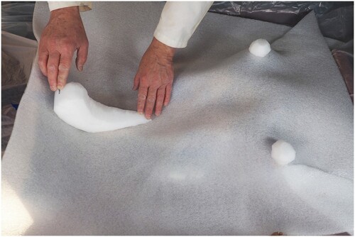
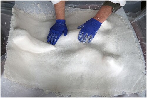
Step 5—Once the specimen is set up for jacketing, the process of tailoring the liner of the first side of the jacket is roughly the same process for all the liner materials. Measure and cut a generous, single sheet of liner material that will cover both the specimen and a 75 mm margin all around it. With the poly-foam liners this is a suitable time to lightly abrade one surface of the sheet with a wire brush or sandpaper. The goal is to raise a slight nap or fuzz on the surface without wearing through the sheet completely. This nap will allow the plaster to adhere to the foam in a mechanical bond. Without it, the liner will later separate from the shell. Remember which side of the sheet is which, or mark with a pen. The smooth side of the foam will rest against the specimen, the outer rough side will receive the plaster. Felt liners do not need this sort of texturing.
Lay the liner on top of the specimen, then carefully use sandbags to conform the liner sheet to the fossil. Unless the specimen has a very low profile, the liner will pucker in places, resulting in folds of excess material. Experiment with different sandbag arrangements to find the one that creates the fewest folds. Cutting the liner along the top of the fold allows the material to then lie flush against the specimen: a technique tailors call a dart ().
FIGURE 6. The lining material has been laid over the specimen and set in place with sandbags, and locations for darts are being determined and created.
There are any number of methods for binding a dart. The dart only needs to be bound long enough for the plaster to take hold, so the most expedient methods will save time and effort.
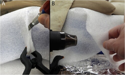
Poly-foam responds readily to heat, so the quickest and most archival method of binding a poly-foam dart is by welding the overlapping sides of the dart with a heat gun. After making the initial dart cut, leave the overlapping flaps of the dart intact. Shield the specimen under the area to be welded with aluminum foil (). Heat both surfaces to be welded simultaneously and press them together immediately. Because this reaction takes, and lasts, only a fraction of a second, this technique requires some practice. Note that melting poly-foam produces toxic fumes, so use proper ventilation for quick welds, and use a fume hood for extensive work or carving it with a hot knife.
FIGURE 7. The sequence to create a welded dart is to, A, cut along the fold in the liner, shield the specimen under the area to be welded with aluminum foil, B, overlap and heat both contact surfaces simultaneously with a heat gun until they are tacky, and press them together. This technique takes some practice but is the quickest and most archival method of binding a dart.
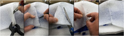
For a matched, sewn seam, make the initial dart cut. Hold the liner in place against the specimen, overlapping the two flaps of the dart, then use a pen to trace the far edge of the overlap on the liner. Draw hash marks across both sides of this edge, the length of the seam, about 25 mm apart. The traced edge will describe a wedge shape to one side of the initial cut. Cut this wedge shape out and take the liner off the specimen. Use polyester thread to sew the dart while lining up the hash marks, a simple running stitch or whipstitch will suffice. This will make the seam conform to the shape of the specimen (). Alternatively, hot melt glue can be used to bind the overlapping flaps of the dart on either felt or poly-foam liners.
FIGURE 8. The sequence to create a sewn dart is: A, cut the liner to where the crease begins; B, overlap the sides, mark the seam line along the cut edge, and draw hash marks across that edge; C, cut the resulting wedge out of the bottom section of the overlap; D and E, line up the hash marks and stitch the seam together with polyester thread.
A hybrid welding technique for foam is to cut a matching seam, then weld a 25 mm-wide strip of 3 mm-thick poly-foam over the seam from the plaster side. A matched seam might also be temporarily taped from the specimen side with a low-tack tape, the tape is removed after the shell is finished. Nylon mesh drywall tape can also be used on the plaster side of the liner to bind a dart.
Cut and bind the darts one at a time so that subsequent darts accommodate the fit of previous darts. This might involve marking and even cutting the dart in situ, taking the sandbags and liner off the specimen entirely to sew a dart, then replacing them to check the fit and placement of the next dart.
Once the darts are secured the liner may be trimmed to the final jacket profile, including a 50–75 mm surrounding flange. This helps reduce materials waste by delineating the outer edge of the jacket, but care must be taken that the liner does not shift during plastering otherwise it might cause the jacket to be misaligned and in need of remedial care. Allowing the liner to extend past the flange entails more waste and trimming but ensures the overall alignment will be correct. Once the liner is tailored it is removed from the fossil, the specimen covered in plastic film, then the liner is put back in place.
Step 6—Feet and support structures should be prepared before plaster is mixed (except in the case of 6 mm poly-foam liners where there is an opportunity to fabricate these between the initial and final layers of plaster). Feet provide stability on the shelf, and three feet—a tripod—balances on uneven surfaces better than four. Feet can be cut out of poly-foam plank or built up out of pads of felt or foam. They can be custom carved to fit or straddle uneven jacket surfaces. A simple method is to cut semicircles out of foam plank and find where they can attach to the slopes or flange of the jacket. Feet should be widely spaced, though on long jackets they are best positioned about one quarter the length of the jacket in from the ends, like the support towers of a suspension bridge. They should be just tall enough to keep the jacket from touching the shelf and no more (). One must always be mindful of economizing on shelf space. Even while the jacket is under construction upside down, a straight board can be laid across the feet to simulate a shelf and check height and alignment.
FIGURE 9. The locations and shapes of the jacket feet have been determined, carved out of foam, and placed where they will reside on the jacket. They will be removed and set aside for later inclusion.
On large jackets, hand grips can be added to the rim of the flange by cutting small blocks of plank foam or sections of poly-foam backer rod, and then plastering them into place during Step 7 ().
FIGURE 10. A hand grip that was carved out of poly-foam and plastered onto the flange of a large jacket.
To add structural support to long jackets, ribs may also be cut out of foam plank or backer rod. When these struts are plastered into place lengthwise along the jacket, the resulting tubes will add rigidity to the jacket without embedding metal, as in earlier jackets, which interferes with CT scanning. It is helpful to distress the surface of foam structures with sandpaper or a wire brush before plastering. Feet and other structures should be set aside until it is time to incorporate them into the jacket.
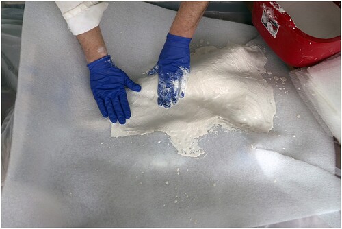
Step 7—Mix a fairly viscous batch of plaster following the manufacturer’s recommendations for that brand and grade. The amount of plaster needed will depend on the size of the jacket—both the dimensions and the weight of the specimen. Small specimens might require as little as 4 layers of 10 mil veil fiberglass and plaster, large specimens as many as 10 layers. Woven fiberglass cloth will require fewer layers than veil. On large specimens an extra set of hands will be helpful. Dust masks, dust extractors, gloves, and a lab coat should be used when cutting or handling fiberglass and mixing and handling plaster.
Apply layers of pre-cut fiberglass cloth to the liner either by dipping the sheets into the plaster one at a time, or ladling plaster onto the liner, then massaging in the fiberglass on top. Smooth each piece of fiberglass to work out any air pockets, but be very gentle working with felt to avoid the plaster seeping through the liner. Overlapping the fiberglass panels slightly will impart added strength (). If the jacket edge has been predetermined, the fiberglass can be folded back onto the jacket along the edge to eliminate trimming later. Always add one extra layer of fiberglass strips on the flange to ensure it is strong enough to withstand handling the specimen using only one side of the jacket.
FIGURE 11. The first layers of plaster and fiberglass being applied to the darted liner resting on the specimen.
When halfway through the process using a 3 mm poly-foam or 6 mm felt liner, add feet and other structures, covering them with the final layers of plaster and fiberglass. It is ideal to complete the plastering goal within one batch of plaster so that the mix and setting are consistent. If plaster must be added to a surface that has set, make sure the set plaster is completely wetted with water before adding new liquid plaster. The final surface can best be smoothed in the last minutes just before the plaster sets up, saving the mess and effort of sanding later.
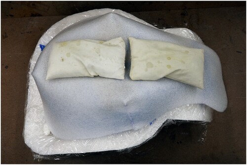
The process for plastering jackets using 6 mm poly-foam liners diverges slightly at the halfway point. After applying three layers of plaster and fiberglass cover the wet jacket with a plastic sheet. Position sandbags over the sheet where good contact with the specimen is required (). It is useful to predetermine the position of the sandbags before plastering, even taking a photograph of the arrangement for quick reference. Weigh the flange down thoroughly. Prior to sandbagging, one trick is to place removable, 50 mm poly-foam strips around the outer perimeter of the specimen to help force the liner to snug up against it. Allow the plaster to set. This technique ensures the thicker foam liner conforms to the specimen.
FIGURE 12. The first three layers of plaster and fiberglass have been applied to the skull of LACM 150150, covered with plastic, and weighed down with sandbags to force the poly-foam liner to conform to the bone until the plaster sets.
After about an hour, when the plaster has set, remove the sandbags and the plastic sheeting. Brush off loose shards of plaster. Wet the jacket thoroughly with water and mix a fresh batch of plaster. Continue applying new plaster and fiberglass to the jacket. Add feet and other structures at layer 5. Smooth the final layer ().
FIGURE 13. The feet have been plastered in place on the jacket, and the plaster surface is being smoothed before setting.
Allow the jacket to dry for 1–2 days. Moving a damp jacket risks the shell distorting and no longer fitting the specimen.
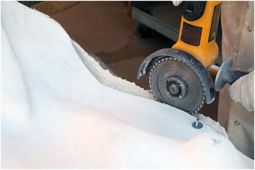
Step 8—After the plaster is dry to the touch, remove the completed jacket half, flip it over, and place on a table. If the liner was not pre-trimmed, re-insert the specimen into the half jacket and mark the flange so there is 50–75 mm of flat area around the entire specimen. Keep the flange to the minimum possible width to conserve storage space while ensuring a tight seal. Remove the specimen again and place safely aside. Using protective gear—gloves, respirator, ear and eye protection, lab coat—and a dust extractor, trim the flange edge of the jacket along your mark, or at the edge of the pre-trimmed liner. This can be done with a fine-toothed reciprocating or oscillating saw, an angle grinder, or rotary tool with a diamond wheel (). Knock out any plaster that may have seeped between the liner seams. With felt liners, remove any plaster that seeped through the felt by scraping or pulverizing the spots with a blunt tool. Round off and smooth the cut edge of the flange with coarse sandpaper or a file. Vacuum the inside of the jacket well. Remaining guide marks can be removed from poly-foam with ethanol.
FIGURE 14. Once the first side of the jacket is dry, A, the flange is marked about 75 mm (or four finger widths) from the specimen. Then the specimen is set aside and, B, the flange is trimmed with an oscillating saw.
Step 9—To create the opposite side, place the jacket onto the specimen and flip the specimen and jacket shell together, or carefully replace the specimen back into the flipped jacket. Though the half-jacketed specimen could be sunk in the sandbox, this is not necessary since the flange of the first side of the jacket will support the flange on the second side (). Prepare the specimen and liner as in Steps 4–6 above.
FIGURE 15. LACM 150150 returned to the first side of its jacket and readied for construction of the second side.
With 6 mm poly-foam liners, once the liner is tailored, trim it so that it only covers the specimen, but does not extend fully over the flange. Make sure this does not create a cavity between the edge of the second liner and the specimen into which the plaster and fiberglass might sink. If so, close that gap with a temporary filler. Remove the liner and cover the specimen AND the flange of the first half in plastic film. Put the liner back in place. Be especially careful not to displace the liner while plastering. This step ensures a tighter fit on the flange when the finished jacket is bolted together (). Apply plaster as above, again following the 2-stage process for 6 mm poly-foam liners.
FIGURE 16. The poly-foam liner for the second side has been made and is being held in place with sandbags. Note that the liner does not extend across the flange.
Keep the second side of the jacket in place while the plaster sets and dries for a couple of days. Early removal of a damp jacket may cause that side to warp during the drying process and prevent the two sides from tightly joining.
Step 10—Once the second half of the jacket is dry to the touch, draw temporary registration marks—like hash marks—on both halves of the flange, or trace the outline of the trimmed side on the untrimmed side, to ensure the halves can be precisely oriented after the specimen has been removed. Take the top jacket off, remove the specimen and place it safely aside, replace the top jacket in its original position using the registration marks, and securely clamp the halves together. Mark the positions on the flange where you want to place the bolts that will hold the two halves of the jacket together. Steel bolts are used for their strength and wide availability. Plan on the minimum number of bolts that will seal the jacket halves all the way around and securely hold the two sides together when flipping the specimen. Typically, this would be four bolts, evenly spaced around the jacket (i.e., one in the center of each side). Very small jackets might require only two bolts, and large, complex, and extremely heavy jackets might need as many as six. Position the bolts in the center of the flange where they will not go through the specimen, a support, or other thick part of the jacket. Carefully drill appropriate diameter holes through the flanges and bolt the two halves of the jacket together.
Unnecessarily long bolts should be avoided whenever possible. Many labs buy in bulk, and 35–40 mm long bolts serve in most situations (machine “thumb” screws, used for this jacket, are easier to manipulate but more expensive) and should not extend more than 12–18 mm above the flange. End users will appreciate taking the least time to unfasten the shortest and fewest bolts possible.
If a specimen is to be imaged in a CT scanner while still in its jacket, the metal bolt assembly can be removed and temporarily replaced with nylon cable ties (zip-ties) or nylon bolts. These nylon alternatives, being weaker than steel, are not advised for the handling or long-term storage of heavy specimens. Trim and sand the flange edges to match the first side () and vacuum the interior of both jacket halves.
FIGURE 17. The specimen was removed from the finished clamshell jacket and set aside while holes were drilled through the jacket flange. Bolts have been installed and the second side is being trimmed and smoothed to match the first side.
Step 11—After the plaster is dry, and not cool to the touch, seal the entire surface, especially the cut edges, with a heavy coat of consolidant. This helps keep the fiberglass particles out of people’s hands as they handle the jacket and makes it easier to write on the surface. Make sure there is adequate ventilation or wear a fitted respirator with organic vapor filter cartridges when brushing on quantities of solvent-heavy consolidant. Write the appropriate identification numbers or specimen name on the jacket and other relevant information using an archival, pigment-based felt-tipped marker. Seal this writing with a topcoat of consolidant. Place the specimen in one side of the jacket and set the other half on top and bolt the jacket together (). Enclosing the specimen in the clamshell before the jacket is sufficiently dry risks mold growth. The time it takes the plaster to dry, or cure, is contingent on local ambient humidity and could vary from days to weeks.
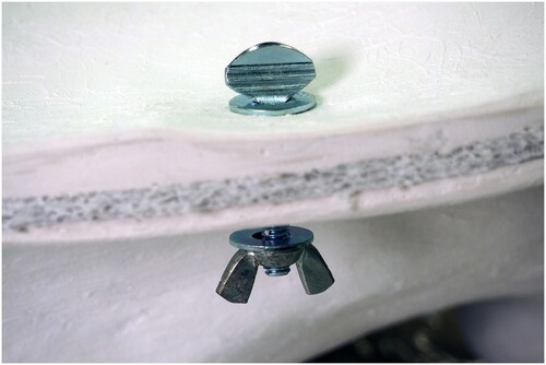
FIGURE 18. Bolt the two sides together, arranging the hardware in the following order: bolt/screw head—washer—flange—washer—wingnut. The bolts should be snugly tightened, but not overtight.
Place all catalog labels and a photo of the specimen in a zip-lock bag, attach it to the jacket, and place the specimen in the collections ().
FIGURE 19. The completed jacket of LACM 150150 resting safely in the collections.
A padded jacket handling protocol for visiting researchers, similar to the one used at NMNH, can be found in the Supplementary Data. A version of this is posted on the NMNH website for visitor requests, and a hard copy is given to visiting researchers when they access the collections. Instructional and informational videos about storage jackets can also be found in the Supplementary Data.
Rollable Jackets
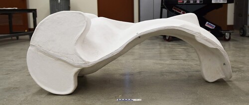
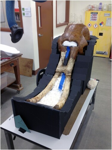
Plaster jackets can be heavy in and of themselves. Many especially weighty specimens cannot be flipped over without the aid of several people and/or mechanical assistance (block & tackle). A technique developed at the NMNH allows large, heavy storage jackets to be rolled over by one or two individuals. This entails the addition of “rockers”—parallel, semi-circular structures—to each half of the jacket along one side (). Execution is similar to that for adding feet or other structures to the jacket and works with jackets made with 6 mm poly-foam or poly-felt. Mastery of basic jacketing techniques is recommended before attempting a rollable jacket.
FIGURE 20. Rockers can be added to the heavy side of large jackets to aid in flipping the specimen over to examine its opposite side. Shown: clamshell jacket for the skull of LACM (CIT) 106/14, Mammuthus exilis, with rockers to aid in flipping the specimen over. (Photo by Stephanie Abramowicz)
Rockers will be added midway through the jacketing process. For jackets using 6 mm foam this is a natural juncture in Step 7, after the initial layers of the shell have set and the sandbags removed. For jackets utilizing a felt liner, construction should be halted after three layers of plaster and fiberglass are applied and the shell allowed to set. At this point the plaster does not need to be smoothed, a rough finish is more of an advantage.
Chances are, with a specimen large enough to warrant this technique, jacketing will not take place in a sandbox, but rather a scaffolding to support the flange will be constructed (). This arrangement makes designing the rockers easier since the entire specimen is to some degree visible. If a sandbox is used, the total height of the specimen along the side where the rockers will go should be measured before being placed in the sandbox. This way the dimensions of the rockers can be approximated.
FIGURE 21. Specimens too large for a sandbox must have their flange surfaces made a different way. Here, scrap foam core has been cut and stacked around the skull of LACM (CIT) 106/14 to create the flange surface along the dividing line.
Determine the side of the specimen where the rockers will go. This should be the heavier and least fragile side. Symmetry will also be of benefit. The first jackets of this type were made for proboscidean skulls—which are egg-shaped—and rockers of roughly equal size were added at the posterior end of the braincase where weight and symmetry aided balance and minimized stress on tusks. Rockers for asymmetrical specimens might need to have different dimensions.
The rockers for both sides of the jacket must create one continuous semicircle. This is where the height of the specimen is critical: this measurement, plus at least 25 mm extra per side, will be the diameter of the rockers. Half of that measurement will be the radius of the semicircle.
These lengths can be used to make a compass out of string or stick, or to measure circular objects like plates or trash can lids to use as jigs. Rocker designs can be worked out on paper, like on profile photos of the specimen, or by using cardboard or foam core to mockup the rockers or create a template. Though working with only one side of the jacket in progress, the second side of the jacket must be imagined to ensure success of the design.
Once a pattern is designed, the rockers can be cut out of 50–75 mm poly-foam plank. Each rocker is essentially one quarter of a circle. Like feet or support struts, the foam will serve as a spacer for the plaster and fiberglass. If the foam has a sealed skin, it should be abraded using sandpaper or a wire brush. The edge of the flange where the two sets of rockers will meet needs to be a straight line roughly parallel to that side of the specimen rather than an undulating line following the actual shape of the specimen. The rockers need to be placed so they extend 12 mm past this straight edged flange, otherwise the flange might be damaged by hitting the floor during flipping ().
FIGURE 22. The rockers on this jacket extend 12 mm beyond the flange in order to protect the flange while flipping the jacketed specimen.
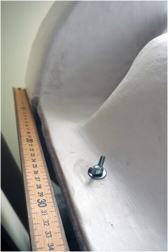
When possible, position the rockers on the flange of the jacket, to either side of the specimen. This will reduce force transmitted directly onto the specimen when flipping. The rockers should be set up parallel to one another, with care taken that they will roll on the same flat plane. A yard/meter stick can help establish that plane. The attachment edge of the rockers might need to be carved a tad so they stand up straight on an uneven jacket. The rockers should be slightly taller than the highest point on the jacket, but not more than 25 mm. Once their position is determined, the rockers can be hot-glued in place on the jacket. If the rockers are freestanding and in danger of damage from lateral stress, buttresses can be carved out of foam and glued to their inner sides reinforcing their attachment to the jacket. The rockers will serve as two feet for the jacket, so a third foot can be attached forming the peak of a triangle with the rockers. Handholds may also be added to the flange where appropriate.
This side of the jacket is then ready for final plastering. The initial plaster surface will need to be wetted down to receive new plaster. Three or more layers of plaster and fiberglass are applied to the jacket as a whole, plus two or three more layers on the rockers. Panels of fiberglass should overlap the join between the jacket and rockers to reinforce those areas as much as possible. The plaster is smoothed as desired.
The jacket should be allowed to dry for several days. Then the flange can be trimmed and the surface consolidated. The specimen will need to be strapped into the jacket in order to flip the jacket and specimen together (if possible, pre-position the straps under the specimen before jacketing). This will require many extra hands and perhaps a hoist. Using the rockers will make this process easier.
(An alternative method for flipping a large, heavy specimen in a half jacket [or mothermold] is to initially center the specimen on a padded sheet of thick plywood about 150 mm larger than the fossil on every side. This should be on a strong lab table where it will be possible to briefly overhang the board/specimen/jacket off the edge of the table—or span a second table—and access the board from underneath. A scaffold is used to support the flange. When the first side of the jacket is complete, the scaffolding is removed and replaced with lengths of solid 50 mm × 100 mm board and other scraps of lumber on three sides of the specimen, with padding between. [Or the scaffolding itself is initially made from stacked lumber.] This frame is first bolted to the underlying board, then to the flange of the jacket. Many hands will still be needed to flip this sandwich, but the safety of the specimen is more assured.)
Cover the specimen and jacket with plastic film and, following the process outlined above, make the second side of the jacket. Special attention should be paid when placing the rockers so that they form a continuous arc with the first set of rockers ().
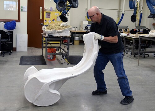
FIGURE 23. AWZ demonstrating how a single person can flip the clamshell jacket with rockers containing the skull of LACM (CIT) 106/14. (Photo by Stephanie Abramowicz)
DISCUSSION
Conclusions
These custom-fit, padded plaster storage jackets have been in development since the early 1990s at the NMNH. As they were put into use, talks, workshops, and publications disseminated the principles of their construction, and they were quickly adopted by many other institutions around the world. They are relatively inexpensive to fabricate and can be made with conventional, widely found, archival materials. This technique has been used to jacket specimens as small as a delicate, 20 cm Late Miocene seal skull, as large as a 220 cm Gorgosaurus vertebral column, and as heavy as a 250 kg Triceratops skull. They can accommodate simple shapes, like turtle shells, or huge, complex Cervalces antlers. While cavity mounts suffice for many smaller specimens, especially delicate fossils may benefit from the 360° support of a clamshell jacket and the reduction in direct handling it offers. Because they are custom made to the specimen’s profile, jackets can help conserve collections space more efficiently than readymade containers.
Because the safety of the specimens is the ultimate goal of these techniques, care must be taken in their execution. A thorough understanding of the nature, behavior, proper mixing and application of plaster is imperative to producing jackets that will be strong enough to protect specimens. The specimens themselves should be stable, clean, and well prepared. Jacket design must be carefully considered. Where the jacket halves join has an impact on the safety as well as ease of examination and imaging of the specimen. Typically, this is near its midline, though the specimen’s morphology or other special conditions may dictate that the dividing line be located off-center. Specimens must be well supported and immobilized within the jacket, yet delicate parts should avoid contact with the interior. During set-up for jacketing, undercuts on the fossil must be filled, temporarily, to prevent the jacket from locking onto the specimen. The jacket must be of an adequate thickness to support the weight of the fossil, yet not overly built so as to make handling and examination of the specimen cumbersome. Feet, flanges, and other structures should be as minimal as practical to conserve collections space. And proper PPE and safety protocols, as detailed above, should be employed while fabricating these jackets.
Future Directions
Workers are constantly refining and adjusting these techniques to fit their unique conditions and fossils, so the authors expect to see variations, improvements, and innovations continue. Creative solutions like embedding casters in jacket shells to aid mobility of weighty specimens, asymmetrical rockers to flip awkwardly shaped fossils, and modular, multi-part jackets have already been prototyped. New, better, and lighter archival materials will likely become available in the future. Testing and reporting on the impact of materials on in-jacket scanning should be undertaken, as should monitoring the potential compression of liner materials over the long term. Plaster and fiberglass are not impervious to stress and failure, so structural solutions to mitigate damage to jackets from exceptionally heavy specimens remains another area for further exploration.
AUTHOR CONTRIBUTIONS
AWZ executed the jackets pictured and took all photographs not otherwise credited. Both authors drafted and edited the manuscript.
Supplemental Material
Download MS Word (17.6 KB)Supplemental Material
Download MS Word (15 KB)Supplemental Material
Download Zip (772.9 MB)Supplemental Material
Download MP4 Video (782.7 MB)Supplemental Material
Download MP4 Video (120.9 MB)DISCLOSURE STATEMENT
No potential conflict of interest was reported by the authors.
ACKNOWLEDGMENTS
The authors would like to thank Jorge Velez-Juarbe and Xiaoming Wang for access to the specimens depicted, and the Natural History Museum of Los Angeles County for use of the photographs. We thank the reviewers for their constructive comments, and the editors who handled the manuscript. We would also like to thank the Smithsonian's William Keyser and all the other preparators, conservators, and collections workers who have made and continue to make improvements to the jacketing process.
SUPPLEMENTARY INFORMATION
Supplementary Data 1: Plaster jacketing supplies and U.S.A. suppliers.
Supplementary Data 2: Padded jacket handling protocol.
AdvancedStorageJackets_copyright2021AlanZdinak.mp4: Instructional video, copyright Alan Zdinak.
Archival Jackets.mp4: Instructional video about clamshell storage jackets. Copyright William Keyser. Used with permission.
LITERATURE CITED
- Chaney, D. S. (1992). Encapsulating Supports for Large Three Dimensional Fragile Specimens. In Carolyn L. Rose and Amparo R. de Torres (Eds.), Workbook for the Storage of Natural History Collections (pp. 95–98). Society for the Preservation of Natural History Collections.
- Fitzgerald, G. R., Chaney, D. S., & Shepherd, M. (1992). Storage system for large objects using form-fitted support pallets and pallet racking. In C. L. Rose and A. R. de Torres, (Eds.), Storage of Natural History Collections: Ideas and Practical Solutions (pp. 91–94). Society for the Preservation of Natural History Collections.
- Jabo, S. J., Kroehler, P.A., Grady, F.V., (2006). A technique to create form-fitting, padded plaster jackets for conserving vertebrate fossil specimens. Journal of Paleontological Techniques, 1, 1–6.