Abstract
Particle emissions from a turbo-charged diesel off-road engine were characterized with DMA + CNC and electron microscopy for comparison of different sampling and dilution systems. Four different sampling methods were used: (1) two ejector diluters, (2) partial flow and ejector diluter, (3) porous tube and ejector diluter, and (4) porous tube diluter. Number size distributions for partial flow and ejector dilution had modes at 25–30 nm and at 45–50 nm independent of the dilution ratio. The mode at 25–30 nm indicated nucleation during dilution in these experiments and was clearly most significant for the partial flow and ejector diluter setup. This was attributed to the temperature difference between exhaust gas, sample line, and partial flow diluter and cold dilution air. For other dilution systems the main mode was at 45 nm and indications of a mode at 15–20 nm were observed depending on the dilution ratio. Especially for the porous tube diluter, the main mechanism for particle growth was condensation on the surfaces of the existing particles. According to this study the best dilution system for obtaining a number size distribution without any significant nucleation effects was the porous tube dilution setup.
INTRODUCTION
Characterization and properties of fine particles has become a topic of increasing interest, as the epidemiological studies have shown a relationship between PM concentrations and death rates (CitationDockery and Pope 1994). However, it is not clear what the fine particle properties are that cause adverse health effects. It has been argued that the particle number concentration may be a better indicator of the health risk than the currently used PM2.5 or PM10 mass concentrations (CitationDonaldson et al. 1998). In addition, the authors point out that important parameters for lung diseases are the size and the chemical composition of the particles.
Emissions from vehicles, and especially from diesel cars and trucks, contain a high number concentration of nano-sized particles (CitationTobias et al. 2001; CitationAbdul-Khalek et al. 1998; CitationKittelson 1998; CitationShi et al. 1999, 2000; CitationShi and Harrison 1999). Since the diesel vehicle exhaust gases contain hydrocarbons and sulphur vapors in the form of SO2(g)/SO3(g) new particles may form by nucleation as the gases cool down. Nucleation is a competing process with adsorption and condensation on pre-existing soot particles. Thus the dynamic behavior of the vapor-particle system in the dilution process will determine the number size distribution after dilution and cooling.
There have been extensive studies on the formation, characteristics, and transformations of the diesel exhaust gas particles related to the measuring setup and dilution techniques, especially with the industry standard dilution tunnel (CitationDolan et al. 1975; CitationAbdul-Khalek et al. 1998; CitationKittelson, 1998; CitationShi et al. 1999, 2000; CitationShi and Harrison 1999). Because the purpose of the dilution tunnel is to simulate the atmospheric dilution process as the exhaust enters the atmosphere, there has been criticism on how well the tunnel actually succeeds in this (CitationKittelson et al. 1999; CitationMaricq et al. 2001). The study by CitationMaricq et al. (2000) also compares the results obtained by ELPI and DMA + CNC and deals with possible problems in this comparison. CitationKittelson and Johnson (1991) have also extensively studied possible causes for variations in number size distributions measured with dilution tunnel setups.
The optimum dilution system depends strongly on the focus of the measurement. The aim may be to simulate the dilution effect when the exhaust gas enters the atmosphere, i.e., to simulate atmospheric dilution. The target may be to preserve the number size distributions as unbiased as possible from the measurement and dilution setup artifacts and to produce a so called “real” size distribution of the particles as observed inside the exhaust pipe. This may be particularly important if a link between the atmospheric dilution and the undiluted exhaust gas needs to be established. Regardless of the dilution system applied the methods are still very much the same: to control dilution ratio (DR), dilution rate, temperature, and residence time to prevent nucleation of hydrocarbon (HC) species and, in the case of high S-content fuel oils, nucleation/condensation of sulphuric acid. Nucleation is a competing process with adsorption and condensation on preexisting soot particles. Thus, the dynamic behavior of this vapor-particle system in the dilution process will determine the number size distribution after dilution and cooling.
In this study four different dilution systems for sampling diesel engine exhaust gas particles are presented. The main focus of this work is to compare the results obtained with the different dilution systems and to identify the discrepancies between different systems. The measurement setup for the comparison is arranged so that the target is to achieve an unbiased “real” number size distribution from the diesel engine excluding the simulation of atmospheric dilution when the exhaust gases leave the exhaust pipe. Since the total particle number concentration and the number size distribution are very sensitive to changes in measurement conditions, they are selected as parameters to compare number concentration and size distribution determined with a DMA + CNC combination. In addition, particle morphology and chemical composition are studied by TEM equipped with EDS.
EXPERIMENTAL METHODS
The engine type operated during the experiments was a 4-stroke, 4-cylinder, 4.4-litre turbo-charged off-road diesel engine with an intercooler (). The fuel used in these experiments was a CEC experimentation fuel (RF - 73 - A – 93) that contained about 433 ppmw of sulphur.
TABLE 1 Engine operating parameters in the experiments
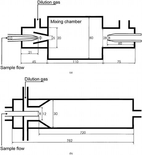
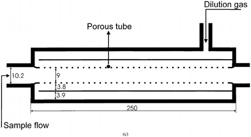
Altogether four different dilution systems () were set up: two ejector diluters (ED; CitationKoch et al. 1988) in series; a commercially available AVL SPC 472 partial flow diluter (Smart Sampler (SS)) in series with an ejector diluter; a porous tube diluter (PRD; CitationLyyränen et al. 1999; CitationLind, 1999) in series with an ejector diluter; and PRD only. The dilution ratio (DR) was varied only in the cases of SS + ED and PRD, the other dilution setups were operated with a constant dilution ratio. The sampling lines to the diluters were heated up to 200°C in all cases except for SS + ED, where the line was at 150°C. PRD is a coaxial cylindrical diluter where the dilution air flows through a porous tube (pore size 20 μm) into the inner tube, thus sheathing the aerosol flow from deposition and thermophoresis (CitationAuvinen et al. 2000). SS is a computer-controlled dilution tunnel; the parameters (flow, temperature, etc.) can be controlled and operated by the computer (). The operating temperatures of the different dilution systems () ranged from 25°C to 200°C. All the other diluters were outside the exhaust pipe except the PRD, which was partly inside. The dilution ratios of the different dilution systems were determined with an exhaust gas NOx-analyzer.
FIG. 1 Schematics describing the different dilution setups applied in the experiments. (a) ED1 + ED2 and SS + ED, (b) PRD + ED and PRD.
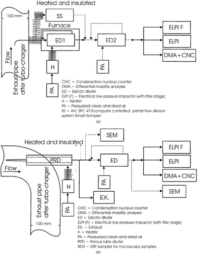
FIG. 2 Schematics (not in scale) of the different diluters applied in this study. (a) Ejector diluter (ED), (b) partial flow diluter Smart Sampler (SS), (c) porous tube diluter (PRD).
The particle samples were collected from the exhaust pipe (diameter 100 mm, flow velocity about 10 m/s) after the engine turbocharger. A differential mobility analyzer (DMA, TSI 3080 with 3081 classifier; Knutson and Whitby 1975) with a condensation nucleus counter (CNC, TSI 3022) together with scanning particle mobility sizer software (SMPS, TSI; CitationWang and Flagan 1990). The measured particle size range for DMA + CNC was 6–221 nm with a preimpactor D50 = 593 nm. In addition, an electrical low-pressure impactor (ELPI; CitationKeskinen et al. 1992) with and without a filter stage was used to measure the number size distributions.
Individual particle samples were collected with a point-to-plate ESP sampler (CitationYeh 1993; CitationLaskin and Cowin 2002) for analysis with scanning electron (SEM) and transmission electron (TEM) microscope to study the particle morphology and elemental composition. To monitor the on-line mass concentration of the exhaust particles a tapered element oscillating microbalance (TEOM 1400 A) was used. In addition, to determine the total mass concentration, glass fiber filter together with low-pressure impactor samples were collected.
The criterion for starting the sampling was such that the engine had completely warmed up (exhaust temperature at the manifold about 180–190°C, lubricating oil temperature about 100°C with low load), and the on-line measured number size distribution did not vary significantly. This is critical to ensure that the data obtained are not mixed with the possible artifacts from other sources. When changing the dilution ratios in the dilution systems, sampling was started 5–10 min after the change. The stability of the aerosol was checked by observing the number size distributions measured by ELPI.
RESULTS
Number Concentrations and Number Size Distributions
Total number concentrations measured with a DMA + CNC are in the range of 2.1–5.2 × 10⁷ l/cm3 for ED1 + ED2, PRD + ED, and PRD dilution systems with low load ().For SS + ED dilution system the total number concentrations are higher, in the range of 0.5–1.1 ×10⁸ l/cm3 (), and increase with increasing primary dilution ratio. Comparing total number concentrations at high and low load for ED1 + ED2 indicates that there is no significant difference at dilution ratio of 108 (DR1 = 10.5, ). On the other hand, for PRD + ED the total number concentration is about 28% higher for high load than for low load. In this case, however, the primary dilution ratios are different; DR1 = 7.8 and DR1 = 10.8 for low and high load, respectively. In addition, the total number concentration for PRD + ED is about 17% higher than for ED1 + ED2 at high load. The primary dilutions ratios are similar, DR1 = 10.8 and DR1 = 10.5, respectively.
TABLE 2 Engine load, dilution ratios, dilution temperatures, total particle number concentrations measured with DMA + CNC, and calculated count median diameters for different dilution systems
Number size distributions at low load with SS + ED are bimodal with a main mode at about 25–30 nm and another mode at 45–50 nm (). Increasing the primary dilution () from DR1 = 2.5 to DR1 = 5.3 and keeping the secondary dilution constant at DR2 = 11.7, increases the total number concentration and the main mode at 25–30 nm. For ED1 + ED2 at constant dilution ratio DRtot = 108 the mode is at about 47 nm (). However, an indication of another mode in the form of a shoulder is also observed at about 10–15 nm. For PRD + ED, DRtot = 58, the main mode is at about 45 nm (). A similar shoulder is observed at about 10–15 nm in one of the number size distributions, whereas in the other case a clear mode at about 15 nm is found. For PRD there is basically always a mode at about 47 nm independent of the dilution ratio (). However, for dilution ratios in the range of DRtot = 10–30 there is an indication of a shoulder at about 20 nm. Also, the total number concentrations are higher with these lower dilution ratios ().
FIG. 3 Number size distributions measured with DMA + CNC for different dilution systems and dilution ratios at low load. (a) SS + ED, (b) ED1 + ED2 and PRD + ED, (c) PRD.
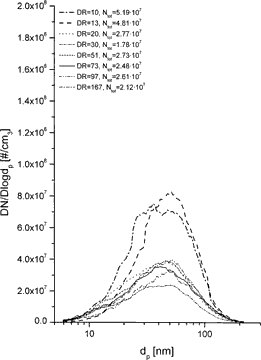
Studying the effect of different dilution systems on the number size distributions at similar dilution ratios indicates that for the ED1 + ED2, DRtot = 108 and DR1 = 10.5 (), there is nearly always a shoulder at about 10–15 nm (). In the case of PRD + ED, DRtot = 58, DR1 = 7.8 () in some cases there is clear mode at about 10–15 nm, in some cases only a small shoulder. For PRD the number size distributions are unimodal at DRtot = 63.
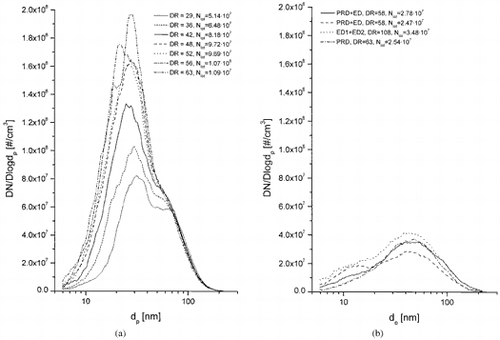
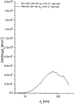
Number size distributions for high load cases with ED1 + ED2 and PRD + ED are clearly unimodal with a mode at about 70 nm (). Comparison of the low and high load cases clearly indicates that the number size distribution mode is shifted to larger particles, from about 45–50 nm to about 70 nm.
FIG. 4 Number size distributions measured with DMA + CNC for different dilution systems and dilution ratios at high load.
The total number concentration for SS + ED increases with dilution ratio (). Conversely, the CMD decreases from 40 nm to 28 nm with increasing dilution ratio in the range of DRtot = 29–63. Because the second stage dilution ratio is constant, this directly indicates the effect of the primary dilution ratio on the CMD.
FIG. 5 Count median diameters (CMD) together with geometric standard deviations (σg) and total number concentrations (Ntot) as a function of dilution ratio (DR) for SS + ED (DR(ED) = 11.7, constant) and PRD dilution systems.
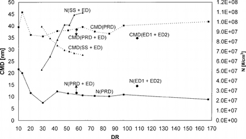
For PRD dilution system the trend is not so simple and clear. In the range of DRtot = 10–30 the total number concentration decreases with increasing dilution ratio. At DRtot = 30, some variation occurred in the total concentration. Therefore, the decrease in the total number concentration up to this point may not be true. The total number concentration becomes approximately constant above DRtot = 30. The CMD, on the other hand, increases from DRtot = 10 to DRtot = 13, and then decreases from 13 to 20. Above DRtot = 30 the total number concentration and the CMD are almost constant.
For ED1 + ED2 at one single point of DRtot = 108 () the CMD is clearly smaller and the total number concentration larger than for PRD. However, with PRD + ED both the CMD and the total number concentration as a function of DR are almost the same as for PRD.
Individual Particle Morphology
The individual particle morphology and composition studied by TEM/EDS indicates that there are spherical primary particle and agglomerate structures. The smaller structures, about 40–50 nm in diameter, represent those particles that are also detected by DMA + CNC (). Also very small particles below 10 nm in diameter are observed (). These nucleated particles are not detected by the CNC + DMA used in this study. Looking at the structure in higher magnification () indicates that there are planes, indicating crystalline structures in these small nanoparticles. Based on the TEM/EDS analyses, individual particle composition and morphology did not seem to heavily depend on the dilution system applied.
FIG. 6 TEM micrographs of individual exhaust gas particles from a turbo-charged off-road diesel engine sampled at the location presented in . (a) An overview of the typical particles found on the sample presenting particles of about 40 nm in size, (b) a close-up of a typical nucleated primary particle of 5–7 nm in size.
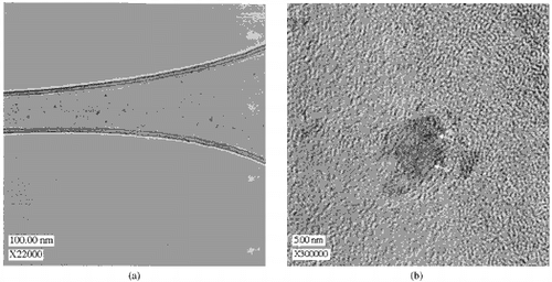
EDS analyses from the agglomerate and 40–50 nm sized particles reveal that they mainly contain carbon and only traces of sulphur and Zn and Si. The small nucleated primary particles of 5–7 nm in diameter contain mainly carbon. Similar layer-like structures as observed by CitationIshiguro et al. (1997) are also seen.
DISCUSSION
Number size distribution is a very sensitive indicator of the changes made in the engine and sampling system. Therefore, it can be used effectively in interpreting the phenomena occurring in the engines. However, care must be taken in the interpretations that no erroneous conclusions are made. Parameters like temperature and dilution ratio—primary and secondary if multistage dilution is used, residence times (, order of magnitude estimates), and mixing effects (rates) in the diluters and in the whole experimental setup should be carefully controlled, for example, as noted by CitationKittelson and Johnson (1991) and CitationAbdul-Khalek et al. (1998).
TABLE 3 Estimated residence times in the different diluters
ED1 + ED2 Dilution System
In this dilution system the primary diluter and dilution air were heated to 185°C () to avoid blocking of the ejector nozzle because of thermophoretic and vapor deposition. The secondary ED was unheated with cold dilution air. The dilution ratio is basically fixed by design at about 1:10 independent of the flow rate. However, pressure differences between the mixing chamber and the sample inlet may exist, which can lead to deviations from the desired dilution ratio (CitationKoch et al. 1988). Because there is only a small temperature difference between the dilution air and the incoming exhaust gas sample flow at low load, 195 and 185°C, respectively, nucleation does not have a significant effect on the number size distribution, although a small shoulder can be seen at about 10–15 nm. At high load the exhaust gas was nearly 200°C hotter than the dilution air in the primary ED (). In this case the shift to larger particles, 45–50 nm at low versus 70 nm at high load, can be caused by the condensation of heavier hydrocarbons (HC).
Mixing in this type of dilution system is fast because the exhaust gas sample flow enters the mixing chamber through a small orifice, i.e., venturi, with very high speed thus ensuring rapid entrainment and mixing (). However, nucleation does not have such a strong effect on the number size distribution because the dilution gas is heated. Indications of nucleation in ED1 + ED2, though, can be seen when comparing particle size and total number concentration as a function of DR for ED1 + ED2 and PRD (). For ED1 + ED2 the particle size is smaller (35 versus 41 nm) and total number concentration higher (3.5 × 10⁷ versus 2.5 × 10⁷, ).
Because of turbulent mixing there is also a possibility for particle deposition near the upstream end of the mixing chamber that potentially can cause loss of large particles, 1 μm or greater in diameter. Because of the focus of this study, fine particles in the size range of 10–500 nm, this does not represent a problem.
Another parameter that may affect the total number concentration and size distribution is residence time in the diluter and in the experimental system. The calculation of the true residence times in the case of ED dilution system is not an easy task. This would possibly require 3D CFD calculations to be accurate and modelling of turbulence in the case of ED to model mixing at inlet of the ejector nozzle and mixing chamber to take into account the geometrical effects. Bulk residence times could be estimated by simple calculations, but these would not take into account mixing at the inlet of the ejector nozzle and mixing chamber and the geometrical effects and flow patterns that are critical in this diluter. Therefore, the benefit may be questionable. Another possibility is to measure the true residence times by tracer techniques. However, a rough estimate for the residence time in the mixing chamber only was calculated based on the flow rate and the volume of the mixing chamber, and it was 870 ms ().
SS + ED Dilution System
The structure of the SS diluter is similar to that in the ED diluter with the exception that the diameter of the nozzle, i.e., venturi through which the sample enters the mixing chamber, is much larger in the case of SS (about 8 mm, ) compared to ED (1 mm). Large temperature difference among exhaust gas (T = 200°C), sample line (T = 150°C), the SS diluter (T = 52°C), and diluting with cold air (T = 25°C) creates favorable conditions for nucleation. In addition, the design of the SS diluter further favors nucleation because mixing in this dilution tunnel is relatively fast. This can be seen in the clear relationship between the nucleation mode at about 25–30 nm and primary dilution ratio for the SS diluter. As the primary DR of the SS increases, the mixing rate with cold air that favors nucleation increases, and as a result, the size of the nucleation mode at 25–30 nm increases. Furthermore, looking at the CMD and the total number concentration it is clear that nucleation occurs in this dilution system: when the DR1 is increased, the total number concentration increases and the CMD decreases ().
In these experiments the residence times in the SS diluter are on the order of 350 ms (tunnel at 52°C at 1.5 g/s flow). Because the total flow through the SS diluter is constant, the sample flow rate increases as the DR decreases and vice versa. The increased dilution rate also favors nucleation.
PRD Dilution System
Even though there is a large temperature difference among the dilution air (T = 25°C), the exhaust gas sample flow and the diluter (T = 200°C), no large nucleation mode can be observed. A shoulder in the range of DRtot = 10–30 can, though, be seen. This disappears when the dilution ratio is increased over DRtot = 30. Because mixing and cooling in the PRD diluter are slow and not perfect, the conditions for nucleation are not favorable. This is the consequence of how the dilution is taking place: the dilution air flows through the small (about 20 μm) pores from the entire distance of the diluter (). The structure of the diluter also causes it to take some time and distance after the diluter until the exhaust gas sample and dilution air are completely mixed. This is to be taken into account if sampling very near the downstream end of the PRD. Some nucleation can take place at the edges of sheathed sample flow, i.e., at the interface between the sample flow and dilution airflow. The main mechanism for particle growth is condensation on the surfaces of the existing particles.
The best way to determine the residence times reliably is experimentally by using tracer techniques. Unfortunately, during the measurement sequence this was not possible. However, on the order of magnitude estimates from other experiments suggest that the residence times are 300–500 ms with the measurement setup applied here ( and ). The total flow through the PRD was the same, i.e., residence time was unchanged and therefore the amount of sample flow increases as the DR decreases and vice versa.
PRD + ED Dilution System
Comparison of PRD + ED to the single stage PRD dilution indicates that in some cases with low primary dilution ratios, DR1 = 7.8, the nucleation mode is stronger than in the PRD. This may be nucleation at the second stage ED dilution but also nucleation at the first stage PRD dilution, thus creating a mutual effect. It seems that nucleation is strongest in the PRD when the DR is lowest. In this case (PRD + ED) the DR in PRD is lower than lowest DR used in the PRD only case. This is another reason for the more distinct nucleation mode with the PRD + ED dilution system. Comparison of the particle size (), the CMD, and the total number concentration of PRD + ED and PRD () also indicates that in some cases the CMD with PRD + ED is lower and total number concentration higher than with PRD.
CONCLUSIONS
In this study four different dilution systems for sampling diesel engine exhaust gas particles were presented. The main focus of this work was to compare the results obtained with the different dilution systems. The measurement setup was arranged so that the target was to achieve an unbiased “real” number size distribution from the diesel engine, excluding the simulation of atmospheric dilution when the exhaust gases leave the exhaust pipe.
The number size distributions for SS + ED were bimodal with a main mode at about 25–30 nm and another mode at 45–50 nm. The main mechanism for changes in the particle number size distribution was nucleation. Indications of nucleation were also observed when increasing the primary dilution ratio of the SS diluter.
For ED1 + ED2 at constant dilution ratio, DRtot = 108 the mode was at about 47 nm. In this case nucleation did not have a significant effect on the number size distribution, although a small shoulder was observed at about 10–15 nm. Indications of nucleation were further confirmed when particle size decreased and total number concentration increased when compared to the values from PRD ().
For PRD no large nucleation mode was observed, though a clear shoulder in the range of DRtot = 10–30 was present, but it disappeared when DRtot was higher than 30. The main mechanism for particle growth was condensation on the surfaces of the existing particles. On the other hand, the diluter provides a possibility for adjustable flow rate of the dilution gas and, therefore, an easy control of dilution ratio. However, only a single engine was studied with only a few different loads. Based on the other measurements made by applying this diluter (CitationLyyränen et al. 1999, 2000), this should not be a problem.
For PRD + ED the nucleation mode was stronger when compared to the case when only PRD was used. This was caused by nucleation occurring at the second stage ED dilution. However, some nucleation may also have occurred in the PRD, thus creating a mutual nucleation effect. Another reason for the more distinct nucleation mode with the PRD + ED was the lower PRD dilution ratio that was lower than the lowest dilution ratio used in the PRD-only system.
Based on TEM/EDS analyses, individual particle composition and morphology did not seem to depend heavily on the dilution system applied. Large, irregular-shaped and catenulate agglomerates consisting of small spherical particles of 20–50 nm in diameter were observed. The agglomerated particles were possibly re-entrained from surfaces or partly agglomerated during sampling. Smaller primary particles of 5–7 nm in diameter that had indications of crystalline structures were also observed. The primary particles seemed to be mainly nucleated hydrocarbons. In addition, particles consisting of smaller structures about 40 nm in size were seen. This was also the size class that peaked in the number size distributions.
Based on the observations of this study the best dilution system for obtaining a “real,” i.e., unchanged, number size distribution excluding the simulation of atmospheric dilutio when the exhaust gases leave the exhaust pipe or the nucleation effects is the PRD dilution. It does not have a significant nucleation mode even with low dilution ratios, though an indication of nucleation mode is present with low dilution ratios. On the other hand, to obtain a clear nucleation mode, and thus to obtain information on this mode, the SS + ED dilution system is suitable because of fast cooling and mixing.
| ABBREVIATIONS | ||
| CFD | = |
Computational fluid dynamics |
| CMD | = |
Count median diameter |
| CNC | = |
Condensation nucleus counter |
| DMA | = |
Differential mobility analyzer |
| DR | = |
Dilution ratio |
| ED | = |
Ejector diluter |
| EDS | = |
Energy dispersive X-ray analyzer (analysis) |
| ELPI | = |
Electrical low pressure impactor |
| ESP | = |
Electrostatic precipitator |
| HC | = |
Hydricarbon(s) |
| PRD | = |
Porous tube diluter |
| SMPS | = |
Scanning mobility particle sizer |
| SS | = |
AVL SPC 472 partial flow diluter smart sampler |
| TEM | = |
Transmission electron microscope |
| TEOM | = |
Tapered element oscillating microbalance |
| σg | = |
Geometric standard deviation |
Acknowledgments
This study was funded by VTT Processes. Dr. Unto Tapper is acknowledged for his contribution for TEM and EDS analyses.
Notes
1 Residence time in the mixing chamber.
2 As specified by manufacturer.
3 Estimated by model calculations based on experimental temperature data.
REFERENCES
- Auvinen , A. , Lehtinen , K. E. J. , Enriquez , J. , Jokiniemi , J. K. and Zilliacus , R. 2000 . Vaporisation Rates of CsOH and CsI Conditions Simulating Severe Nuclear Accident . J. Aerosol Sci. , 31 : 1029 – 1043 .
- Abdul-Khalek , I. S. , Kittelson , D. B. , Graskow , B. R. , Wei , Q. and Brear , F. 1998 . Diesel Exhaust Particle Size: Measurement Issues and Trends 133 – 145 . SAE paper 980525
- Backman , U. , Jokiniemi , J. K. , Auvinen , A. and Lehtinen , K. E. J. 2002 . The Effect of Boundary Conditions on Gas-Phase Synthesised Silver Nanoparticles . J. Nanoparticle Research , 4 : 325 – 335 .
- Dockery , D. W. and Pope , C. A. 1994 . Annual Reviews of Public Health , 15 : 107 – 132 .
- Dolan , D. F. , Kittelson , D. B. and Whitby , K. T. 1975 . Measurement of Diesel Exhaust Particle Size Distributions 1 – 7 . ASME paper 75-WA/APC-5
- Donaldson , K. , Li , X. Y. and MacNee , W. 1998 . Ultrafine (Nanometre) Particle Mediated Lung Injury . J. Aerosol Sci. , 29 : 553 – 560 .
- Ishiguro , T. , Takatori , T. and Akihama , K. 1997 . Microstructure of Diesel Soot Particles Probed by Electron Microscope: First Observation of Inner Core and Outer Shell . Combust. Flame , 108 : 231 – 234 .
- Keskinen , J. , Pietarinen , K. and Lehtimäki , M. 1992 . Electrical Low-Pressure Impactor . J. Aerosol Sci. , 23 : 353 – 360 .
- Kittelson , D. B. 1998 . Engines and Nanoparticles: Review . J. Aerosol Sci. , 29 : 575 – 588 .
- Kittelson , D. B. , Arnold , M. and Watts , W. F. 1999 . Personal Communication, UNM report, 64 p.
- Kittelson , D. B. and Johnson , J. H. 1991 . Variability in Particle Emission Measurements in the Heavy Duty Transient Test 1 – 26 . SAE Tech. Pap. Ser., paper 910738
- Knutson , E. O. and Whitby , K. T. 1975 . Aerosol Classification by Electric Mobility: Apparatus, Theory and Applications . J. Aerosol Sci. , 6 : 443 – 451 .
- Koch , W. , Lodding , H. and Munzinger , F. 1988 . Verdünnungsystem für die Messung hochkonzenrierter Aerosole mit optischen Partikelzähler . Staub—Reinhaltung der Luft , 48 : 341 – 344 .
- Laskin , A. and Cowin , J. 2002 . On Deposition Efficiency of Point-to-Plate Electrostatic Precipitator . J. Aerosol Sci. , 33 : 405 – 409 .
- Lind , T. 1999 . Ash Formation in Circulaiting Fluidised Bed Combustion of Coal and Solid Biomass , VTT publications 378 PhD. Thesis
- Lyyränen , J. , Jokiniemi , J. , Kauppinen , E. I. and Joutsensaari , J. 1999 . Aerosol Characterisation in Medium-Speed Diesel Engines Operating with Heavy Fuel Oils . J. Aerosol Sci. , 30 : 771 – 784 .
- Lyyränen , J. , Jokiniemi , J. and Kauppinen , E. I. 2000 . The Effect of Mg-based Additive on Aerosol Characteristics in Medium-Speed Diesel Engines Operating with Residual Fuel Oils . J. Aerosol Sci. , 33 : 967 – 981 .
- Maricq , M. M. , Chase , R. E. and Xu , N. 2001 . A Comparison of Tailpipe, Dilution Tunnel, and Wind Tunnel Data in Measuring Motor Vehicle PM . J. Air & Waste Management Assoc. , 51 : 1529 – 1537 .
- Maricq , M. M. , Podsiadlik , D. H. and Chase , R. E. 2000 . Size Distributions of Motor Vehicle Exhaust PM: A Comparison Between ELPI and SMPS Measurements . Aerosol Sci. Tech. , 33 : 239 – 260 .
- Shi , J. P. and Harrison , R. M. 1999 . Investigation of Ultrafine Particle Formation During Diesel Exhaust Dilution . Environ. Sci. Technol. , 33 : 3730 – 3736 .
- Shi , J. P. , Harrison , R. M. and Brear , F. 1999 . Particle Size Distribution from a Modern Heavy Duty Diesel Engine . Sci. Total Environ. , 235 : 305 – 317 .
- Shi , J. P. , Mark , D. and Harrison , R. M. 2000 . Characterisation of Particles from a Current Technology Heavy-Duty Diesel Engine . Environ. Sci. Technol. , 34 : 748 – 755 .
- Tobias , H. J. , Beving , D. E. , Ziemann , P. J. , Sakurai , H. , Zuk , M. , McMurry , P. H. , Zarling , D. , Waytulonis , R. and Kittelson , D. B. 2001 . Chemical Analysis of Diesel Nanoparticles Using NanoDMA/Thermal Desorption Particle Beam Mass Spectrometer . Environ. Sci. Technol. , 35 : 2233 – 2243 .
- Wang , S. C. and Flagan , R. C. 1990 . Scanning Electrical Mobility Spectrometer . Aerosol Sci. Technol. , 13 : 230 – 240 .
- Yeh , H.-C. 1993 . “ Instrumental Techniques/Electrical Techniques ” . In Aerosol Measurement—Priciples Techniques and Applications , Edited by: Willeke , K. and Baron , P. A. 410 – 426 . New York : Van Nostrand Reinhold .