Abstract
Optical pyrometers that operate in gas turbine aeroengines are exposed to contaminate particulates from the atmosphere of the operating environment, which can deposit on the instrument's lens and thus foul the system's optics. This particle deposition process results in the attenuation of the thermal radiation signal, from the pyrometer's measurement target, due to transmission losses through the layer of deposits on the lens. A purge air system is therefore employed to minimize the level of optical contamination. This article outlines the generic air-purging configurations and highlights their operation through providing both flow field and particle trajectory analyses via computational fluid dynamics (CFD) in order to provide an evaluation of their operating performance.
INTRODUCTION
Optical pyrometry provides an effective means of direct temperature measurement of the turbine blades in gas turbine aeroengines. However, the greatest concern with the in-service use of pyrometry is the issue of fouling, since the device's lens is exposed to the turbine environment. The level of optical contamination can be minimized by incorporating a purge air system into the pyrometer design, whereby an air flow is sent down the pyrometer's sight tube to prevent particles in the turbine gas stream from coming in contact with the lens and therefore prevent the associated buildup of contaminants on its surface. This article provides a review and evaluation of the basic purge air designs applicable to the problem of particulate contamination of pyrometer lenses.
BACKGROUND
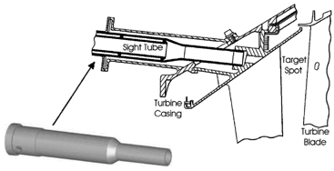
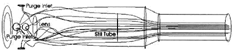
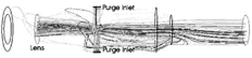
Optical pyrometry is a noncontact method of surface temperature measurement that does not perturb the surface of the target material or surrounding medium. The technique is based on determining the temperature of an object by a measurement of the thermal radiation that is emitted from the object's surface. The device operates by collecting thermal radiation from a defined surface area, which is optically transferred to a detector, to produce an electrical signal proportional to the surface's radiant power. The optical pyrometers that are installed in gas turbine aeroengines provide direct temperature measurements of the turbine blades, with the resulting data being the primary input for providing a realistic assessment of the components' operating history and associated life usage. These devices have their sight tube assemblies mounted to project through to the turbine chamber in order to view the turbine blades as depicted in . The function of the sight tube assembly housing the pyrometer lens is to define the target spot and collect the emitted thermal radiation from the blades. However, this means that the pyrometer is open to the particle-laden gas stream of the turbine, and unfortunately the target on the turbine blade may become obscured due to particle deposition on the pyrometer lens.
FIG. 1 Optical pyrometer installation.
Even though only one optical surface is exposed to the turbine environment, the resulting deposition of particulates from the combustion process and atmospheric ingestion can greatly inhibit the benefits of utilizing such an instrument. These particulates, such as soot and sand, constitute optical fouling of the system and result in the attenuation of thermal radiation due to transmission losses through the lens. The optical contamination is basically acting as an interference filter by absorbing some of the thermal radiation from the blades resulting in an output signal that is representative of a lower temperature than the actual blade temperature. This is a very important problem especially when the pyrometer is operating to prevent overtemperature exposure of the turbine blades because the output signal will be biased low to produce a reduction in indicated temperature. The control system may then permit higher turbine temperature operation, resulting in blade temperatures in excess of their intended limits and thus shortening blade life.
CitationBarber (1969) was the first to note that particulate deposition on the lens would be the “most likely source of trouble in operation,” and CitationKirby (1986) further reinforced this point by stating: “lens contamination is of crucial importance since it constitutes a fail-dangerous error mode (erroneous low reading).” Therefore, the pyrometer lens must be maintained free from deposits if accurate temperature readings are to be maintained. In practice, a purge air system is therefore incorporated into turbine pyrometer designs in order to minimize the number of particulates that can potentially deposit and buildup on the exposed system optics. This is accomplished by introducing purge air, bled from the compressor, down the sight tube to prevent both the buildup of contaminants on the exposed system optics and particles in the turbine gas stream from coming in contact with the lens.
SOURCES OF CONTAMINATION
There are only two sources of lens fouling within any pyrometer purge air system (CitationKerr and Ivey 2001). The first and most obvious is gas stream particles in the turbine chamber that enter through the sighting aperture of the sight tube. It is this source of contamination, termed turbine chamber penetration, that the purge air system is employed to minimize, if not prevent. The operating mechanism of the purge system is to provide and maintain a positive pressure through the sight tube to prevent particulates in the turbine gas stream from penetrating the sight tube and reaching the lens. Such penetrating particles typically have high inertia and thus the purge airflow must be adequate to redirect these contaminants back around and down the sight tube to re-enter the turbine chamber. The most significant particulate matter in the turbine gas stream is the suspended particulates that result from the combustion process, with soot being the major constituent. Of course, there are many other particles present such as those that have been ingested by the engine, for example sand, and particles from the engine itself through erosion of components, such as protective coatings on the blades.
The other contributing factor to lens fouling, more subtle yet just as significant, is the fact that the source of purge air is bled from the compressor, which means that particles are present in the purge airflow itself. Thus, in certain designs the purge air can actually be attributed to the cause of lens fouling instead than minimizing deposition as was intended. This second source of contamination, termed purge air deposition, whereby particles from the purge air can deposit, is sometimes easily overlooked in some systems. Compressor bleed air is used as the supply for the pyrometer purge system, and it is usually particle-laden with particulates that originate from the surrounding atmosphere ingested by the engine. A simple solution would be to remove these particles in the purge air through the use of a filter; however, such items are not favored due to maintenance issues, weight, and the fact that this is another component that must be added to the aeroengine together with the subsequent ramifications that may then emerge with its installation and maintenance. An examination, through electron microscopy and nondispersive X-ray analysis, of the particles that constitute the lens fouling can be found in CitationKerr and Ivey (2002).
GENERIC PURGE AIR CONFIGURATIONS
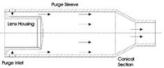
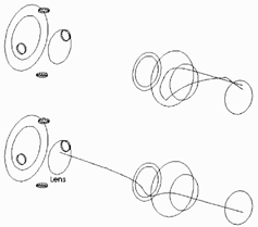
The design concept for pyrometer purge air systems is to flow purge air down the elongated cylindrical sight tube that houses the lens. The action of the out-flowing purge air serves to stop most particles from flowing up through the sighting aperture and contacting the lens. In general, the sight tube assembly consists of the lens housing, basically a tube that holds the lens in position, and a purge sleeve, which is another tube that fits in front of the lens housing and has a number of purge inlets for the introduction of the purge air, as illustrated in . It should be noted that the purge inlets can be of any desired number sufficient to provide an adequate volume of purge flow and are generally circular in shape. The purge sleeve consists of both cylindrical and conical sections that define a funnel-shape. The resulting converging profile of the purge sleeve means that it functions as a nozzle so that the velocity of the purge airflow increases through the conical section in order to minimize any backflow within the sight tube that would otherwise draw particles in from the turbine chamber.
FIG. 2 Fundamental purge design.
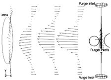
Air Curtain Configuration
The design concept for the air curtain configuration, shown in , is to provide an airflow in front of the lens, thus establishing a barrier that prevents any contaminants from entering the sight tube. However, two disadvantages do emerge from this approach, namely particles may become trapped and then accumulate in the dead air zone between the lens and air curtain (CitationHayden et al. 1988). Secondly, there is no mechanism for removing any particles that may settle on the surface of the lens after the aeroengine shuts down, excluding of course cleaning during routine maintenance (CitationKerr and Ivey 2001).
FIG. 3 Air curtain configuration.
Air Scrubbing Configuration
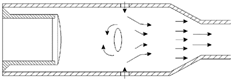
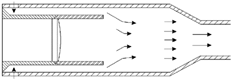
The air scrubbing approach utilizes the layer attachment or Coanda effect, whereby the purge airflow is directed over the lens surface so as to form a barrier to prevent any particulates penetrating the sight tube from coming into contact with the lens. As the purge air flows over the lens it tends to scrub across its surface () and any particles on the lens will be re-entrained (CitationBerenblut and Masom 1982; CitationHayden et al. 1988; CitationMacKay 1990). The purge must be controlled so as to maintain an adequate flow velocity to insure that any particles that are removed from the lens remain entrained and are carried outwardly away from the lens. An important advantage of this generic configuration is that the scrubbing action permits the removal of ignition phase deposits that may form during engine start-up (CitationBerenblut and Masom 1982). Also any particles that deposit as the aeroengine shuts down, due to gravitational settling for example, are then removed when the purge system begins to operate with engine start-up. However, CitationHayden et al. (1998) acknowledged two principal disadvantages with the scrubbing approach: first, any particles in the purge air itself are brought to the lens, thus increasing the likelihood of deposition; and second, although the scrubbing action can remove large particles the technique experiences difficulty in removing submicron particles or large sticky particles already deposited.
FIG. 4 Air scrubbing configuration.
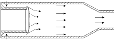
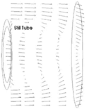
Still Tube Configuration
The design concept for the still tube configuration is the same as the air curtain, i.e., to provide an airflow barrier in front of the lens. However, this barrier of purge air is formed with the addition of a still tube extension in front of the lens, as presented in . The still tube has the function of establishing a still region in front of the lens to prevent any contaminants, even those in the purge air itself, from depositing on the lens (CitationKerr and Ivey 2001). The major disadvantage with this configuration is that there is no mechanism for removing any particles that may settle on the surface of the lens after the aeroengine shuts down, except manual cleaning conducted through routine maintenance.
FIG. 5 Still tube configuration.
NUMERICAL MODELING OF THE PURGE AIR SYSTEMS
Analysis of the three generic purging configurations (air curtain/air scrubbing/still tube) was conducted using computational fluid dynamics (CFD) to provide not only a deeper insight and understanding of each purging mechanism but also a performance evaluation. Solutions were acquired for the purging systems at the steady-state pressure operating condition, termed engine cruise, in order to discover the important flow features that develop within each of the designs. The primary features to identify within the study of purge system airflows are any recirculations within the sight tube that may draw in contaminants or otherwise enhance particle deposition onto the pyrometer lens. In addition to particle penetration from the turbine chamber up into the pyrometer sighting tube, particles were also injected into the purge flow to study deposition from the purge air itself.
Modeling Setup
The solver chosen for the numerical study was FLUENT 5, which is a commercially available finite volume code produced by Fluent Incorporated (CitationFluent 1998). The GAMBIT program, which is a part of the FLUENT package, was the preprocessor used for geometry modeling and mesh generation for all of the grids produced in this study. For modeling purposes, all three configurations share the same relative dimensions contained within an overall sight tube length of 160 mm. The purge air for each configuration is fed from a plenum surrounding the purge sleeve through a row of four inlets which are offset by an angle of 90 °, with each inlet being circular in shape and having a diameter of 5 mm. Through using GAMBIT, the three purge air system volumes were meshed using unstructured tetrahedral grids. The major motivation for using unstructured grids employing tetrahedral cells was the reduced mesh generation time.
FIG. 6 Mesh for air scrubbing configuration.
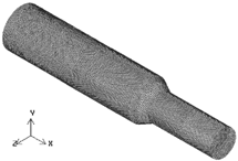
Since CFD solutions require the use of finite grid spacings, the meshes must be generated in such a way that they correctly resolve the flow phenomenon of greatest importance without negatively affecting the accuracy of the solution or exceeding the computational resources available. Thus, a solution must be shown to be insensitive to the spacing of the grid to demonstrate that adequate mesh resolution has been used. Therefore, mesh independence tests were conducted whereby a series of grids with significantly differing resolutions were run until an acceptable balance of accuracy and computational complexity was achieved. For the models in this study, an example of which is illustrated in , the resultant meshes contained in the region of 470,000 to 500,000 cells.
For the flow specification, a set of gas turbine representative boundary conditions were chosen for the numerical simulations with the purging systems operating under the steady-state conditions of engine cruise, as specified in . Within FLUENT, several test runs of the models were conducted in order to find the appropriate numerical schemes and settings to use, thus facilitating the constraints of computational cost versus accuracy. The 3D, steady-state, segregated solver was found to be appropriate together with the SIMPLE method for pressure-velocity coupling. Since cyclonic swirls develop within the designs, the renormalization-group (RNG) k-e turbulence model provided the best balance in terms of run time, with a turbulence intensity of 10% and associated length scale of 0.1 mm. This solution strategy was validated experimentally through employing Laser Doppler Anemometry with a full-scale model of an actual in-flight pyrometer purge system (CitationKerr 2002).
TABLE 1 Boundary conditions for numerical simulations
Analysis of Flow Fields
The essence of a purge air system is to maintain a positive flow through the sight tube to prevent combustion gases with suspended particles from entering the pyrometer and contaminating the lens; show this positive purge flow for each of the three configurations.
FIG. 7 Purge air pathlines for the air curtain configuration.
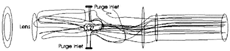
FIG. 8 Purge air pathlines for the air scrubbing configuration.
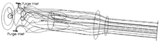
FIG. 9 Purge air pathlines for still tube configuration.
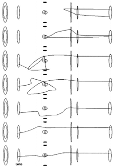
Consider first the air curtain purging system (); although this design does produce a positive purge flow out through the sight tube, analysis of the purge air velocity vectors shows that there are in fact significant recirculations within the sight tube as illustrated in (significant is defined as large recirculations within the purge system that result in the establishment of a negative flow toward the pyrometer). This not only results in an inefficient use of the purge airflow but leads to the formation of a backflow which develops when the purge air enters the inlets and the inlet jets mix. The development of this backflow () results in a major proportion of the purge air coming in contact with the pyrometer lens; should there be any particulates in the purge air then this backflow mechanism will greatly enhance the level of purge air deposition.
FIG. 10 Recirculations in the air curtain configuration.
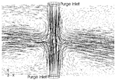
FIG. 11 Backflow in the air curtain configuration.
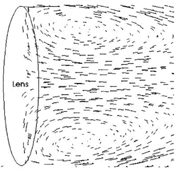
For the air scrubbing purging system (), it can be seen that this configuration will produce a more effective purge flow, i.e., a purge flow that results in a lower level of lens fouling, through the sight tube compared to the air curtain system. However, there are a number of pathlines in that swirl in front of the lens. Upon closer inspection, it appears that instead of the purge air scrubbing across the lens there is a negative recirculation, depicted in , as the purge sweeps around the lens, analogous to the flow situation of a backward-facing step. This flow feature actually presents the fact that rather than developing a scrubbing action across the lens with the advantage of re-entraining any particles on the lens, such as the removal of ignition phase deposits or gravitationally settled particulates, the purge airflow actually enhances the buildup of deposits onto the lens.
FIG. 12 Recirculation in the air scrubbing configuration.
Finally, consider the analysis of the flow field for the still tube purging system (). depicts the airflow pathlines maintaining the positive flow through the sight tube; however, illustrates that some of these pathlines may flow around the mouth of the still tube, which protects the pyrometer lens, and down its length. Analysis of the velocity vectors (), shows that there is significant swirl or recirculation in front of the still tube mouth. Although only shows the swirl effect in a 2D cross-section, this recirculation is of course a 3D circumferential effect. The swirl that develops can be seen to converge a distance in front of the still tube mouth where a portion of the purge air undergoes a 180 ° direction change as it sweeps around from the annular passageway between the purge sleeve and outer wall of the still tube. This redirection of airflow is presented in . The danger with establishing this type of flow structure within the purge system is that it can draw contaminants through and down into the still tube, and once this airflow penetrates the core of the still tube it can then set up a highly cyclonic swirling flow. This means that any contaminants drawn into the still tube will eventually deposit onto the lens, resulting in lens fouling.
FIG. 13 Purge flow into the still tube.
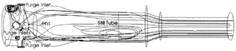
FIG. 14 Recirculatioin in the still tube configuration.
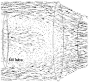
FIG. 15 Flow redirection in front of the still tube mouth.
Analysis of Particle Behavior
Using FLUENT's built-in particle-tracking capabilities, particles were injected into the purge airflow to determine the level of particle deposition onto the surface of the pyrometer lens due to both purge air deposition and turbine chamber penetration. The level of deposition on the lens was evaluated in terms of the percentage particle deposition as defined by
Consider first the level of fouling due to contaminant particles in the purge air. An analysis of the percentage particle deposition versus particle diameter was conducted, through CFD modeling, for all three purge configurations, the results of which are presented in . The air curtain system shows a constant level of fouling, averaging at 27%, since a fixed portion of the particulates injected into the purge air will follow the backflow mechanism to impact upon the lens ().
FIG. 16 Level of purge air deposition.
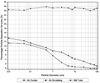
FIG. 17 Purge air deposition in the air curtain configuration.
For the air scrubbing design, there are essentially three regions to the level of purge air deposition onto the pyrometer lens. First, for particles having a diameter smaller than 0.01 μm there is a constant level of deposition of approximately 13.5%. This is due to the fact that these smaller particles have a tendency to follow the airflow and therefore a fixed portion will become entrained by the negative recirculation in front of the lens. Secondly, there is a transition region between 0.01–100 μm whereby the number of particles depositing on the lens decreases linearly with increasing particle diameter. This transition region is described by the function:
Analysis of the still tube configuration shows essentially the same three regions that have a contribution to purge air deposition as with the air scrubbing system. For particles less than 0.01 μm there is a constant level of deposition of approximately 11.5%. These smaller particles remain entrained with the purge airflow, and therefore a fixed portion will become captured by the swirl at the still tube mouth such that they then flow down the still tube to impact the lens. There is also a transition region between 0.01–50 μm whereby the number of particles drawn into the still tube, due to the swirling pattern at the still tube mouth, and depositing on the lens decreases with increasing particle diameter. The transition region of the still tube system is described by the sigmoid:
FIG. 18 Purge air deposition in the still tube configuration.
Consider next the level of optical contamination due to turbine gas path particles penetrating the pyrometer sight tube; ideally the purge airflow should redirect any particulates back into the turbine chamber as depicted in . However, certain particles with a high enough inertia can shoot directly up through the sight tube and into the still tube to impact with the lens ().
FIG. 19 Turbine chamber penetration in the still tube configuration.
Analysis of the percentage particle deposition versus particle diameter, with an initial particle velocity of 100 m/s due to turbine chamber penetration was conducted at the steady-state operating condition and these results are presented in . This graph shows that there are essentially three regions that have a contribution to the problem of lens fouling for each of the purge air configurations. Firstly, for each system there is negligible deposition below a specific particle diameter. For instance, contaminants penetrating the air curtain configuration with an initial velocity of 100 m/s and particles having a diameter less than 30 μm are completely redirected back out of the sight tube, since they do not have enough inertia to overcome the opposing purge airflow. For the air scrubbing and still tube configurations this minimum critical particle diameter is 80 μm and 75 μm, respectively. Secondly, there is a transition region through a range of particle diameters whereby the number of particles that have the ability to impact and thus deposit on the lens increases with increasing particle diameter. For the air curtain design, this transition region is linear and is expressed by the function
FIG. 20 Level of turbine chamber penetration.
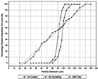
FIG. 21 Turbine chamber penetration in the air curtain configuration.
CONCLUSION
The task of the pyrometer purge air system is to keep the instrument's lens, clean, or at least to minimize the level optical fouling, and there are principally three generic purge designs that can be utilized, namely, the air curtain, air scrubbing, and still tube configurations. An evaluation of these three designs was conducted through computational fluid dynamics (CFD) in order to determine the level of particle deposition, or level of lens fouling, and thus allow the respective operational performances to be compared.
The air curtain configuration provides an airflow in front of the lens, thus establishing a barrier that prevents any contaminants from entering the sight tube. This system was capable of stopping particles, having an initial velocity of 100 m/s, up to a diameter of 30 μm. Should there be any contaminants in the purge air itself, this design exhibited a constant level of particle deposition, averaging at 27%, since a fixed portion of the particulates injected into the purge air will follow the backflow mechanism that is established when the airflow of the purge inlet jets mix.
The air scrubbing design operates by directing the purge airflow over the lens so as to scrub across its surface. However, from flow field analysis it was found that there was a negative recirculation that develops in front of the lens, and this flow feature actually enhances the buildup of deposits onto the lens. This configuration had a purge air deposition profile of 13.5% at 0.01 μm, down to 0% at 100 μm. In terms of particle penetration up the sight tube, the air scrubbing design was capable of completely redirecting particles with a diameter up to 80 μm and an initial velocity of 100 m/s.
The still tube configuration, as its name implies, employs a still tube extension in front of the lens in order to establish a still region of air that will prevent any contaminants, even those in the purge air itself, from depositing on the pyrometer lens. The predominant flow feature within this system was the significant recirculation, or swirl, of the purge air in front of the still tube mouth. Once this swirl pattern is developed a subsequent negative flow is established into the core of the still tube. This motion will significantly increase the likelihood of contaminants coming in contact with the lens surface and depositing to result in optical fouling. However, this configuration did offer the lowest level of purge air deposition with a profile of 11.5% at 0.01 μm down to 0% at 50 μm. For deposition due to turbine chamber penetration, the still tube configuration was capable of stopping particles having an initial velocity of 100 m/s, up to a diameter of 75 μm—only slightly less effective compared to the air scrubbing system.
In making a comparison between each configuration, the air curtain design exhibited the highest level of particle deposition for both purge air deposition and turbine chamber penetration. It therefore had the worst operating characteristics and performance of all the three generic configurations. The air scrubbing system had the most effective barrier for preventing contaminants from penetrating the sight tube and depositing on the lens. Overall the still tube configuration offered the lowest level of purge air deposition and, with a comparable level of turbine chamber penetration to the air scrubbing design, presented the most effective pyrometer purge air configuration.
Acknowledgments
The authors would like to acknowledge the UK Engineering and Physical Sciences Research Council and Rolls-Royce plc as project sponsors, and to thank C. Bird and P. Loftus for the guidance received during the course of this study.
REFERENCE
- Barber , R. 1969 . A Radiation Pyrometer Designed for In-Flight Measurement of Turbine Blade Temperatures, SAE 690432, National Air Transportation Meeting, New York, 21–24 April
- Berenblut , B. J. and Masom , R. A. 1982 . Radiation Pyrometry for Gas Turbine Engines—An Introduction . British J. Non-Destructive Testing , 24 ( 5 ) : 268 – 269 .
- Fluent Incorporated . 1998 . FLUENT 5 User's Guide , Cavendish Court, , Lebanon : Fluent Incorporated .
- Hayden , T. , Myhre , D. , Pui , D. Y. H. , Kuehn , T. H. and Tsai , C. J. 1988 . Evaluating Lens Purge Systems for Optical Sensors on Turbine Engines AIAA-88-3037, AIAA/ASME/SAE/ASEE 24th Joint Propulsion Conference, Boston, 11 –13 July
- Kerr , C. I. V. 2002 . Purge System Design for the Application of Optical Pyrometry in Aeroengines, EngD thesis, School of Engineering Cranfield University Cranfield, , U.K.
- Kerr , C. I. and Ivey , P. C. 2001 . A Review of Purge Air Designs for Aeroengine Based Optical Pyrometers ASME 2001-GT-0580, 46th ASME International Gas Turbine and Aeroengine Technical Congress, Exposition and Users Symposium, New Orleans, LA, 4–6 June
- Kerr , C. I. and Ivey , P. C. 2002 . Particle Deposition on Optical Pyrometer Lenses: An Illustrative Case Study . J. Aerosol Sci. , 33 ( 11 ) : 1577 – 1588 .
- Kirby , P. J. 1986 . Some Considerations Relating to Aero Engine Pyrometry AGARD-CP-399, Advanced Instrumentation for Aero Engine Components, The Propulsion and Energetics Panel 67th Symposium, Philadelphia, 19–23 May
- MacKay , C. G. 1990 . Temperature Measurement in Turbine Engines Allied-Signal Inc., US Patent 4,934,137