Abstract
Particle formation and growth in a TEOS/O2 radiofrequency (rf) plasma were studied by an in situ laser light scattering (LLS) technique and ex situ scanning electron microscopy (SEM). The particles, after being generated, were located around the sheath near the electrodes. Visualization using a high-resolution video camera shows that the particles are trapped around the sheath near the powered electrode (showerhead) and are ultimately located in localized regions between the showerhead holes. Particle-free regions are present immediately below the holes and their surroundings within a certain radius. The particles form a lump cloud when a low gas flow rate is used, change to a line shape when the flow rate is increased, and finally the LLS technique can no longer detect them when high flow rates are used. The particle trapping behavior described above clearly has an influence on particle contamination on the wafer. The particles appear to grow through coagulation as shown by the SEM images of particles taken from the trap regions. A high gas flow rate and high substrate temperature tend to suppress particle formation and growth. On the other hand, particle formation and growth are enhanced with increasing rf power.
INTRODUCTION
Plasma-enhanced chemical vapor deposition (PECVD) of silicon dioxide thin films using a tetraethylorthosilicate (TEOS) and oxygen plasma has become a viable technique in a very large scale integration (VLSI) technology (CitationTochitani et al. 1993). A major advantage of this technique is that the substrate can be maintained at a low temperature during the deposition process, allowing deposition over different types of substrates including temperature-sensitive materials such as polymers and low-melting-point metal films. SiO2 films prepared by this method have demonstrated good step coverage (CitationWickramanayaka et al. 1997), as well as electrical (CitationDeCrosta and Hackenberg 1996) and mechanical properties (CitationRamkumar et al. 1993) preferable for use in interlayers, gate oxides, and passivation layers in VLSI technology. However, it has been shown that for particles generated during the thin film deposition process using a TEOS/O2 plasma the film surface morphology undergoes degradation (CitationFujimoto et al. 2000).
Particles generated in the plasma become negatively charged due to the higher mobility of electrons over ions and consequently undergo levitation by the large electric field in the sheath region. Particles are subject to various forces that may include neutral gas drag, ion drag, electrostatic, gravity, and thermophoretic. This combination of forces causes the particles to be trapped in localized regions where the forces are balanced. Experimental observations have shown that the traps are located at the plasma/sheath boundaries, corresponding to the maximum potential field where the uniformity of the electric field of the sheath is perturbed due to material discontinuities in the electrodes (CitationSelwyn et al. 1991; CitationCarlile et al. 1991). In parallel plate plasmas, in which one of the electrodes is in a showerhead configuration where the gas flows in, the particles are not trapped uniformly below the showerhead, but they are trapped in discrete localized regions between the showerhead holes, and particle-free regions are present just below the holes and their surrounding area within a certain radius. The localization of a particle trap has a great impact on particle contamination of the wafer, particularly when the plasma is extinguished (CitationSetyawan et al. 2003).
In our previous studies, however, the spherical and monodisperse particles were fed into the plasma reactor from the outside. These differ from actual plasma processes in which particles are generated in the gas-phase somewhere within the reactor due to gas-phase nucleation and growth. The growth region can be either localized in the plasma/sheath boundary near the rf electrode or spread over a region corresponding to the plasma/sheath boundary to the plasma bulk region, which is dependent on the rate of radicals production, a factor that is responsible for nucleation and the initial growth of particles (CitationKawasaki et al. 1998). In addition, the particles have a size distribution and may not be spherical. Since the origin, size distribution, and morphology of particles are different for the two cases, the question may arise as to whether the structure and localization of a particle trap are also observed in actual plasma processes using reactive gases such as a TEOS/O2 plasma. These need to be clarified to achieve a better understanding of particle contamination control.
In the present work, particle trapping behavior in a radiofrequency (rf) TEOS/O2 plasma was systematically investigated using a laser light scattering (LLS) technique. The effect of gas flow rate, rf power, and substrate temperature were examined. The mechanisms of particle formation and growth are discussed based on an in situ observation using an LLS technique and an ex situ observation using scanning electron microscopy (SEM). Finally, the relationship between the particle trapping behavior in the plasma and particle contamination on the Si substrate is discussed.
EXPERIMENTAL WORKS
The experimental set up of the PECVD reactor used for the preparation of films from TEOS and oxygen has been described previously (CitationFujimoto et al. 2000). The plasma reactor is a conventional parallel-plate type with an rf discharge of 13.56 MHz. A detailed description of the reactor has been given elsewhere (CitationSetyawan et al. 2002a,b). The reactant gases are introduced through the upper plate, a showerhead configuration, and are coupled to the rf power supply. The lower plate is grounded. The electrodes are 200 mm in diameter and are separated by a distance of 35 mm. The output power of the rf generator was varied from 100 to 400 W in the forward direction, whereas the reflected power was matched to approximately zero using a matching controller.
A mixture of TEOS diluted in nitrogen gas as the carrier and oxygen were introduced into the plasma reactor through the showerhead. The total gas flow rate was varied from 60 to 400 standard cm3/min (sccm), whereas the ratio of oxygen to nitrogen, and the TEOS concentration were fixed at 1 and 5.0%, respectively. The flow rate was controlled by a mass flow controller (SF-2600, Tylan General) for nitrogen and oxygen and by a liquid mass flow controller (LV210, STEC, Inc.) for TEOS. The reactor was evacuated to a base pressure of less than 1.33 Pa using a dry pump (A-30, Ebara Co., Ltd.) before each experimental run. The operating pressure was fixed at 4.0 Torr. Particle formation and growth were studied under the conditions of room temperature and a substrate temperature of 300°C.
Particle formation and the trapping behavior were observed by means of an LLS technique. The LLS measuring system has been described elsewhere (CitationFujimoto et al. 2000; CitationSetyawan et al. 2002a,Citationb). Briefly, a laser beam derived from an Ar+ laser (model 2017, Spectra Physics) was expanded into a sheet by a rod and cylindrical lens to illuminate the space between the electrodes through one of the windows in the reactor. The light scattered by the particles was detected by a camera positioned perpendicular to the light sheet. To study particle formation and growth, an image-intensified charge-coupled device (ICCD) camera (IMAX 512, Princeton Instruments Inc.) was used to detect the light scattered by particles suspended in the space between electrodes. The signal was passed through a frame buffer and was recorded using a personal computer (PC). However, for purposes of visualization to investigate particle trap behavior, a higher resolution CCD camera (DCR-VX2000, Sony) was used instead of the ICCD camera because the latter was not able to clearly capture the movement of particles and the structure of particle clouds in the trap.
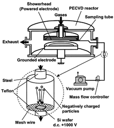
The size and morphology of the generated particles were observed by SEM. The particles were drawn from the trap locations by inserting a sampling tube into the plasma reactor. A schematic diagram of the particle sampling system and the particle collector is shown in . A silicon wafer was placed on a wire mesh installed on the bottom of a larger tube that was located downstream where a positive dc voltage of 1000 V was applied. This arrangement enables the negatively charged particles to be collected on the Si wafer.
Particle sampling was carried out by sucking the particles out of the trap location using a vacuum pump for a short period (∼5 s) when the plasma duration reached 30 s in which stable particle clouds have been formed. The inserted sampling probe charges up to floating potential that may present a potential barrier for negatively charged particles. The effect of potential barrier is more significant for larger particles because they carry more charges. Hence, it is conceivable that large particles are extracted from the plasma with lower probability than small particles. The effect of potential barrier on the measurement of particle size distribution could be eliminated by controlling the flow rate of the sucking gas in such a way so that the gas drag force exceeds the electrostatic force due to the potential barrier (CitationKondo et al. 2003). Therefore, all generated particles, including the large ones, have nearly the same probability to be extracted from the plasma, and the potential barrier would not significantly affect the measured particle size distribution.
The extracted particles may be lost in the tubing and fittings during their transport to the collector. This may affect the measured size distribution because the losses are dependent on the particle size. In order to obtain an insight on this effect, we estimated particle transport efficiency in the tubing and fittings using the equations described by CitationHinds (1999) that include losses due to diffusion to the tube walls, settling, and bending. The transport efficiency due to the above mechanisms in our sampling system is estimated to be in the range from 98 to 99% for particle size ranging from 0.03 to 0.6 μm. The transport efficiency decreases with decreasing particle size for particles smaller than 0.03 μm and reaches about 96% for 0.01 μm particles. On the other hand, it decreases with increasing particle size for particles larger than 0.6 μm and reaches about 94% for 1 μm particles. Therefore, it can be considered that the measured size distributions are not considerably affected by the particle losses during their transport.
RESULTS AND DISCUSSION
Particle Trapping Behavior
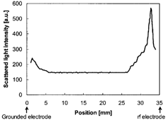
Particle generation in the gas phase can be observed in TEOS/O2 PECVD for all conditions under study at a pressure of 4 Torr. For some conditions, particularly at high gas flow rates, the LLS technique cannot detect particles because of a very low particle concentration or a very small particle size. However, using the sampling technique described earlier, SEM observations show the presence of particles in the plasma reactor. The generated particles are trapped in the plasma/sheath boundaries near both the powered and the grounded electrodes. It appears that particle generation mainly takes place in the plasma/sheath boundaries near the electrodes as shown by the spatial distribution of the scattered light intensity in . Peaks of the scattered light intensity appear near both electrodes. When the plasma was turned on, the system was free of particles. The particles came into sight near the electrodes immediately, when the plasma was turned on. Both particle size and concentration grew over time, thereby scattering more light and making the clouds appear to become thicker. The final shape of the particle clouds is dependent on plasma operating conditions.
FIG. 2 A typical spatial distribution of the scattered light intensity in the space between the electrodes.
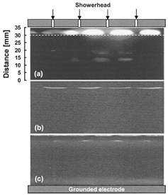
shows data on the dependence of the structure of particle clouds below the showerhead on the gas flow rate. The clouds are located in discrete, localized regions between the showerhead holes, and free-light-scattering regions are present just below the holes and their surrounding areas at a certain radius, regardless of the gas flow rate. The trap regions are static points where particles are not affected so much by the gas drag force. When the gas flow rate exceeds 400 sccm, the particle clouds below the showerhead cannot be detected by the LLS technique. For the case of a low gas flow rate, the particles form a lump cloud which is different from that observed for a high gas flow rate where the clouds are in the shape of a line. Similar phenomena have been observed previously by injecting particles from the outside that we referred to as the lumping mode and the winding mode for the cases of low and high gas flow rate, respectively (CitationSetyawan et al. 2002b). When the gas flow rate is high, the neutral drag force presses the clouds more strongly without changing the equilibrium position of the trap that causes the clouds to shrink. It appears that the origin of the particles, i.e., whether they are injected from the outside or are generated somewhere inside the plasma reactor, has no effect on the structure and trap location of the particle clouds below the powered electrode.
FIG. 3 Dependence of the particle cloud structure in the trap below the showerhead (powered electrode) on total gas flow rate for an rf power of 200 W and room temperature: (a) 60 sccm, (b) 200 sccm, and (c) 300 sccm.
When the rf power is increased, the particle clouds become smaller and thinner. Upon increasing the rf power, the ion density increases, thus increasing the ion drag force, since this force is proportional to the ion density (CitationBarnes et al. 1992). The ion drag force drives the particles toward the showerhead surface. Moreover, the electric field in the sheath becomes stronger with increasing rf power (CitationEdelberg and Aydil 1999). The electrostatic force acting on the charged particles then becomes stronger because this force is proportional to the intensity of the electric field. The electrostatic force drives the particles away from the showerhead surface. The two stronger forces, i.e., the ion drag and electrostatic, that act oppositely on the particles compress the particle clouds and they become smaller and thinner.
The particle clouds at a substrate temperature of 300°C are more compressed compared to the particle clouds at room temperature. In addition, the clouds are closer to the powered electrode. When the substrate is heated to 300°C, a temperature gradient exists between the heated grounded electrode and the powered electrode that is not heated. Therefore, the particles are pushed toward the powered electrode by the thermophoretic force that is present due to the temperature gradient. This causes the clouds to become more compressed and to be located closer to the electrode.
Particle Formation and Growth
The visualizations described above only provide information concerning the structure and spatial distribution of particles in the trap. In order to understand particle formation and growth, the intensity of the scattered light in the trap regions near the electrodes was examined. It is not possible to obtain separate information on both size and particle concentration from the scattered intensity, but it provides information on the combination of both. The particle size was deduced from scanning electron microscopy (SEM) images of particles deposited on the Si wafer by drawing the particles from the trap using the sampling system described earlier.
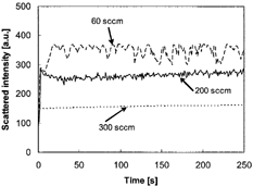
shows the effect of gas flow rate on particle formation at room temperature. A similar trend can be observed for the condition where the substrate temperature is 300°C. The scattered light intensity decreases when the total gas flow rate is increased. It appears that particle growth is suppressed at high gas flow rates. This was also observed by CitationMatsuoka et al. (1999) for the case of a silane rf plasma due to the increase in loss of neutral clusters responsible for particle growth. The residence times of TEOS vapor, intermediates, and primary particles in the plasma reactor become longer when the gas flow rate is decreased. This provides more time for the primary particles formed to grow, resulting in a larger particle size (CitationKim and Ikegawa 1996). When the growing particles reach a critical size or concentration, above which the plasma cannot confine them any longer, they are released from the trap. The particles can also be observed to escape from the trap through the edge of the powered electrode. Because of the low residence time of the process gases, a high gas flow rate tends to remove potential particle generation from the sheath before they are able to form particles in the nucleation sites and provides the less opportunity for the primary particles to grow. SEM photographs of the particles show that the particles are larger at a low gas flow rate and are smaller at a high gas flow rate. This will be discussed below.
FIG. 4 Dependence of particle formation on gas flow rate. The data are at room temperature and rf power 200 W.
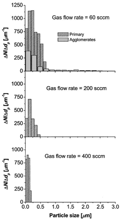
shows examples of SEM images of particles drawn and deposited onto the Si wafer using the sampling technique described above for the conditions at room temperature () and a substrate temperature of 300°C (). The total gas flow rate is 60 sccm. The particles were drawn from the trap when the plasma duration reached 30 s. The particles are composed of smaller primary particles that serve as precursors for larger agglomerated particles. This suggests that the particles in the TEOS/O2 plasma are grown by coagulation as in the case of the silane plasma (CitationBouchoule et al. 1991; CitationShiratani et al. 2000). The primary particles are spherical in shape. For the case of the substrate temperature of 300°C, the boundary among the primary particles is not clear, suggesting that surface deposition has occurred. The size distribution of the primary and agglomerated particles, as deduced from an SEM image, for the room temperature conditions is shown in . The size of the primary particles is larger for lower gas flow rates. This suggests that at low gas flow rates the particles have sufficient time to grow by surface condensation resulting in larger primary particles prior to agglomeration (CitationHaaland et al. 1994). The size of the primary particles becomes smaller with increasing gas flow rate and the size of the agglomerated particles shows a similar trend. These data confirm that particle growth is suppressed at a high gas flow rate, as discussed earlier.
FIG. 5 SEM images of particles drawn from the trap at a gas flow rate of 60 sccm and an rf power of 200 W at (a) room temperature, and (b) a substrate temperature of 300°C. The particles form an agglomerate consisting of several primary particles. The particle boundary is clear at room temperature but is not clear at a substrate temperature of 300°C.
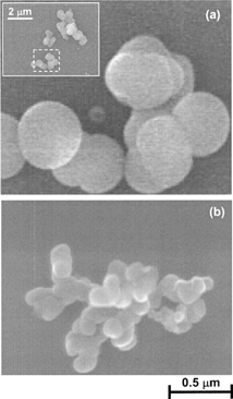
FIG. 6 The size distribution of primary particles drawn from the trap near the powered electrode at an rf power of 200 W as a function of gas flow rate at room temperature. The particle size distribution of the agglomerates deduced from SEM images using Feret method is shown for the case of gas flow rate 60 sccm.
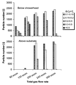
In order to obtain more precise information on amount of particles in the trap, particles were drawn using the same system as above except that the particle number in a line was counted by a particle counter, and not deposited on the Si wafer. The measurement system using the particle counter has been described elsewhere (CitationKondo et al. 2003). The lower detectable size limit of the particle counter is approximately 0.1 μm. Measurements were performed for 5 s, and the number of particles that accumulated was counted. Thus, this measurement only shows the relative amount of agglomerated particles in the trap. shows the particle number drawn from the trap near the powered and grounded electrodes as a function of gas flow rate. We found that the lower the gas flow rate the fewer the number of particles. However, the number of larger agglomerated particles is higher at low gas flow rates. The particles in the trap region near the grounded electrode are very few at low gas flow rates. It appears that most of the intermediates responsible for particle formation and growth are consumed in the region near the powered electrode. On the other hand, at high gas flow rates the number of particles is almost the same as that in the region near the powered electrode. This suggests that at high gas flow rates the intermediates that have the potential to generate particles are carried away from the sheath near the powered electrode by the gas flow, as discussed above. Therefore, sufficient amounts of molecules to form particles are still present near the grounded electrode.
FIG. 7 Number of particles in the trap near the powered and the grounded electrodes counted by the in-line particle counter by drawing the particles for 5 s as a function of gas flow rate.
shows a histogram of the Feret diameter of agglomerated particles deduced from an SEM image at a substrate temperature of 300°C. The effect of gas flow rate is the same as that at room temperature. The primary particle size is much smaller than for the experiments at room temperature, as shown in . This suggests that a high substrate temperature tends to suppress particle formation and growth. This effect of temperature on particle formation has also been observed in the case of silane plasmas (CitationDorier et al. 1992; CitationRao et al. 1998; CitationShiratani et al. 2000). Although the mechanism has not been clarified yet, CitationShiratani et al. (2000) proposed that, under the influence of thermophoresis, almost all neutral particles are driven out of the plasma space, and only negatively charged particles are trapped around the plasma/sheath boundary near the rf electrode. This would prevent their agglomeration because of the mutually repulsive forces between them, resulting in a smaller particle size.
FIG. 8 The size distribution of agglomerated particles drawn from the trap near the powered electrode at an rf powers of 200 W and 400 W, and a substrate temperature of 300°C as a function of gas flow rate.
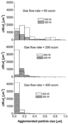
Particle generation is enhanced by increasing the rf power as shown by the increase in the scattered light intensity with increasing rf power. In addition, particle size distribution deduced from SEM images shown in also confirms that particle generation is enhanced by increasing the rf power. The generation of radical species that form particles through gas phase clustering reactions is increased by an increase in power level (CitationRao et al. 1998). This leads to an enhancement in the formation of primary particles. When the concentration of primary particles exceeds the positive ion density that can be achieved at high rf power, agglomeration is considerably enhanced (CitationKim and Ikegawa 1996; CitationKortshagen and Bhandarkar 1999). If the particle concentration is less than the electron concentration, most of the particles will be negatively charged, thus preventing them from agglomeration and, as a result, particles will grow through a much slower surface deposition. Thus, it can be expected that the particle size would increase by increasing the rf power.
Effect of Particle Trapping Behavior on Particle Contamination
In order to clarify effect of particle trapping behavior on particle contamination on the silicon wafer, a silicon wafer was placed on the grounded electrode. It was then exposed to the TEOS/O2 plasma for about 5 min. Particles deposited on the wafer were observed using SEM. We observed that the plasma duration is sufficient to allow the formation of stable clouds below the powered electrode. shows SEM images of particles deposited on the wafer for gas flow rates of 60 sccm, 200 sccm, and 300 sccm, respectively, at room temperature. Numerous particles were deposited on the wafer for gas flow rates of 60 sccm and 300 sccm and only a few for a gas flow rate of 200 sccm. It appears that particle deposition decreases with increasing gas flow rates, then reaches a minimum level and eventually increases again. This trend was also observed in our previous findings, although it was observed in experiments using an inert gas, with the particles being injected into the reactor from the outside (CitationSetyawan et al. 2003). The particles deposited on the wafer placed on the grounded electrode have the sizes in the range of particle size observed in the trap for each gas flow rate. This suggests that they originate from the trap regions and are deposited on the wafer after the plasma is turned off, as was also observed in the previous study (CitationSetyawan et al. 2003). Because the particles fall on the wafer after the plasma is turned off, the level of particle contamination on the wafer will be influenced by the size and concentration of particles in the trap. At low gas flow rates, the generated particles trapped near the powered electrode are large and their concentration is high. When the particles are large, they tend to deposit on the wafer because they cannot follow the gas pathlines when they approach the wafer. At high gas flow rate, more particles are trapped near the grounded electrode.
FIG. 9 SEM images of the contaminated wafers after exposure to the plasma for 5 min: (a) 60 sccm, (b) 200 sccm, and (c) 300 sccm. The brighter images show the presence of particles.

The effect of particle trapping behavior on contamination of the Si wafer in a TEOS/O2 plasma for silica thin film preparation was evaluated. Since the trapping behavior is dependent on plasma operating parameters such as gas flow rate, rf power, and temperature, the level of particle contamination is also dependent on them. For example, by changing the gas flow rate, the particles form a lump shape at low gas flow rate, change to a line shape with increasing gas flow rate, and finally the LLS technique is not able to detect them any longer at a high gas flow rate. The trend of particle-trapping behavior and contamination level is similar to our previous observations in which an inert gas was used and monodispersed particles were injected from the outside (CitationSetyawan et al. 2003).
CONCLUSIONS
Particle formation, trap, and contamination in TEOS/O2 PECVD process were studied by an in situ laser light scattering technique and ex situ scanning electron microscopy. The particle clouds are dependent on plasma parameters such as rf power, gas flow rate, and substrate temperature. The particles form a lump shape at low gas flow rates, change to a line shape with increasing gas flow rates, and finally the LLS technique is not able to detect them any longer at high gas flow rates. When the rf power is increased, the particle clouds are compressed by the stronger electrostatic and ion drag forces acting oppositely on the particles. By heating the grounded electrode to 300°C, thermophoresis due to the temperature gradient shifts the particle clouds upward towards the powered electrode.
High gas flow rate appears to suppress particle formation and growth due to the effect of washing of the intermediates responsible for particle formation and growth. Particle formation is enhanced by increasing rf power due to an increase in the generation of intermediates that form particles through gas phase clustering reactions. Hence, agglomeration is enhanced because the concentration of the primary particles is increased. The particles produced at conditions where the substrate is heated are smaller, suggesting that agglomeration is suppressed at high substrate temperature.
The particle trapping behavior clearly affects particle contamination. Numerous particles are deposited on the wafer for gas flow rates of 60 sccm and 300 sccm and only a few for a gas flow rate of 200 sccm. Gas flow rates are related to the different trapping behavior of the particle trap as described above. It appears that particle contamination decreases by increasing the gas flow rate, then reaches a minimum level and eventually increases again.
Acknowledgments
We thank Y. Imajo for help in the experimental work. This work has been supported by Innovation Plaza Hiroshima of the Japan Science and Technology Corporation (JST). Financial support provided for H. Setyawan by the QUE project, Department of Chemical Engineering, Sepuluh Nopember Institute of Technology (ITS), Indonesia is gratefully acknowledged.
REFERENCE
- Barnes , M. S. , Keller , J. H. , Forster , J. C. , O'Neill , J. A. and Coultas , D. K. 1992 . Transport of Dust Particles in Glow-Discharge Plasmas . Phys. Rev. Lett. , 68 : 313 – 316 .
- Bouchoule , A. , Plain , A. , Boufendi , L. , Blondeau , J. Ph. and Laure , C. 1991 . Particle Generation and Behavior in a Silane-Argon Low-Pressure Discharge Under Continuous or Pulsed Radio-Frequency Excitation . J. Appl. Phys. , 70 : 1991 – 2000 .
- Carlile , R. N. , Geha , S. , O'Hanlon , J. F. and Stewart , J. C. 1991 . Electrostatic Trapping of Contamination Particles in a Process Plasma Environment . Appl. Phys. Lett. , 59 : 1167 – 1169 .
- DeCrosta , D. A. and Hackenberg , J. J. 1996 . Charge Issues in High Oxygen Gas Ratio Tetraethylorthosilicate Plasma Enhanced Chemical Vapor Deposition Films . J. Vac. Sci. Technol. A , 14 : 709 – 713 .
- Dorier , J.-L. , Hollenstein , Ch. and Howling , A. A. 1992 . Powder Dynamics in Very High Frequency Silane Plasmas . J. Vac. Sci. Technol. A , 10 : 1048 – 1052 .
- Edelberg , E. A. and Aydil , E. S. 1999 . Modeling of the Sheath and the Energy Distribution of Ions Bombarding rf-Biased Substrates in High Density Plasma Reactors and Comparison to Experimental Measurements . J. Appl. Phys. , 86 : 4799 – 4812 .
- Fujimoto , T. , Okuyama , K. , Shimada , M. and Fujishige , Y. 2000 . Particle Generation and Thin Film Surface Morphology in the Tetraethylorthosilicate/Oxygen Plasma Enhanced Chemical Vapor Deposition Process . J. Appl. Phys. , 88 : 3047 – 3052 .
- Haaland , P. , Ibrani , S. and Jiang , H. 1994 . Fluid Dynamics and Dust Growth in Plasma Enhanced Chemical Vapor Deposition . Appl. Phys. Lett. , 64 : 1629 – 1631 .
- Hinds , W. C. 1999 . Aerosol Technology: Properties, Behavior, and Measurement of Airborne Particles , 2 , New York : Wiley-Interscience .
- Kawasaki , H. , Sakamoto , K. , Maeda , S. , Fukuzawa , T. , Shiratani , M. and Watanabe , Y. 1998 . Transition of Particle Growth Region in SiH4 RF Discharges . Jpn. J. Appl. Phys. , 37 : 5757 – 5762 .
- Kim , K. S. and Ikegawa , M. 1996 . Particle Growth and Transport in Silane Plasma Chemical Vapor Deposition . Plasma Sources Sci. Technol. , 5 : 311 – 322 .
- Kondo , K. , Imajo , Y. , Shimada , M. and Okuyama , K. 2003 . “ Measurement of Trapping Behavior of Dust Particles During Plasma Process by Suck-Out Method (In Japanese) ” . In Kagaku Kogaku Ronbunshu in press
- Kortshagen , U. and Bhandarkar , U. 1999 . Modeling of Particulate Coagulation in Low Pressure Plasmas . Phys. Rev. E , 60 : 887 – 898 .
- Matsuoka , Y. , Shiratani , M. , Fukuzawa , T. , Watanabe , Y. and Kim , K. S. 1999 . Effects of Gas Flow on Particle Growth in Silane rf Discharges . Jpn. J. Appl. Phys. , 38 : 4556 – 4560 .
- Ramkumar , K. , Ghosh , S. K. and Saxena , A. N. 1993 . Stress Variations in TEOS-Based SiO2 Films During Ex-Situ Thermal Cycling . J. Electrochem. Soc. , 140 : 2669 – 2672 .
- Rao , N. P. , Wu , Z. , Nijhawan , S. , Ziemann , P. , Campbell , S. , Kittelson , D. B. and McMurry , P. 1998 . Investigation of Particle Formation During the Plasma Enhanced Vapor Deposition of Amorphous Silicon, Oxide and Nitride Films . J. Vac. Sci. Technol. B , 16 : 483 – 489 .
- Selwyn , G. S. , Heidenreich , J. E. and Haller , K. L. 1991 . Rastered Laser Light Scattering Studies During Plasma Processing: Particle Contamination Trapping Phenomena . J. Vac. Sci. Technol. A , 9 : 2817 – 2824 .
- Setyawan , H. , Shimada , M. , Ohtsuka , K. and Okuyama , K. 2002a . Visualization and Numerical Simulation of Fine Particle Transport in a Low-Pressure Parallel Plate Chemical Vapor Deposition Reactor . Chem. Eng. Sci. , 57 : 497 – 506 .
- Setyawan , H. , Shimada , M. and Okuyama , K. 2002b . Characterization of Fine Particle Trapping in a Plasma-Enhanced Chemical Vapor Deposition Reactor . J. Appl. Phys. , 92 : 5525 – 5531 .
- Setyawan , H. , Shimada , M. , Imajo , Y. , Hayashi , Y. and Okuyama , K. 2003 . Characterization of Particle Contamination in Individual Process Steps During Plasma-Enhanced Chemical Vapor Deposition Operation . J. Aerosol Sci. , 34 : 923 – 936 .
- Shiratani , M. , Maeda , S. , Koga , K. and Watanabe , Y. 2000 . Effects of Gas Temperature Gradient, Pulse Discharge Modulation, and Hydrogen Dilution on Particle Growth in Silane rf Discharges . Jpn. J. Appl. Phys. , 39 : 287 – 293 .
- Tochitani , G. , Shimozuma , M. and Tagashira , H. 1993 . Deposition of Silicon Oxide Films from TEOS by Low Frequency Plasma Chemical Vapor Deposition . J. Vac. Sci. Technol. A , 11 : 400 – 405 .
- Wickramanayaka , S. , Nakanishi , Y. and Hatanaka , Y. 1997 . On the Chemistry of a-SiO2 Deposition by Plasma Enhanced CVD . Appl. Surface Sci. , 113 : 670 – 674 .
