Abstract
Numerical modeling was performed to study the submicron particle dynamics in a confined flow field containing a rotating disk, temperature gradient, and various inlet gas flow rates. The Lagrangian model was employed to compute particle trajectories under the temperature gradient, disk rotation speed, and inlet gas flow rate effects. The trajectories of particles with diameters of 1 μm, 0.1 μm, and 0.01 μm were examined in this study. When the inlet gas temperature was lower than that of the disk, particle-free zones were created due to upward thermophoretic force for 1 μm and 0.1 μm particles. Disk rotation was found to depress the size of the particle-free zone. Particle deposition onto the disk for 0.01 μm particles was possible because of the Brownian motion effect. A detailed evaluation of the particle-free zone size as a function of the temperature gradient, disk rotation speed, and inlet gas flow rate was performed. When the inlet gas temperature was higher than the disk temperature, particle deposition onto the disk was enhanced due to the downward thermophoretic force for 1 μm and 0.1 μm particles. Disk rotation was found to increase the deposition rate. For 0.01 μm particles, Brownian motion was more important than thermophoretic force in controlling particle behavior. The particle deposition rates as a function of the temperature gradient, disk rotation speed, and inlet gas flow rate were performed.
Introduction
Particle transport and deposition are considered important flow phenomena in various industrial applications. For example, chemical vapor deposition (CVD) is an essential element in microelectronic circuit fabrication (CitationJensen et al. 1991). With circuit size becoming smaller, highly pure and uniform thin film is required. To satisfy these requirements, controlling the contaminant levels inside the CVD chamber and operating environment is essential. Particle deposition is one of the methods used for manufacturing optical waveguide preforms on substrates (CitationSchultz 1980; CitationKawachi 1990) and metallic oxides in wide band gap semiconductor manufacturing (CitationOh and Kim 1996). In this case, efficient silica and vapor aerosol particle deposition is desired. In all of the applications mentioned above, particle behavior plays a crucial role in the process performance.
To improve the deposition quality and special features of thin films, most researches involving CVD processes were devoted to thin film growth mechanisms and flow field characteristics inside a CVD reactor (CitationKleijn 2000). However, particle contaminants resulting from the reacting gases and process equipments are also factors that affect thin film quality. Several studies were carried out to investigate the contaminant particle behavior inside a CVD reactor. By solving the particle concentration equation in the flow field, CitationPui et al. (1990), CitationYe et al. (1991), and CitationOpiolka et al. (1994) carried out extensive studies on particle deposition onto wafers in a clean room. CitationOh et al. (1996) performed a numerical analysis to characterize the particle deposition behavior on a horizontal freestanding wafer. The thermopheretic and turbulence effects were included. CitationSchmidt et al. (1996) carried out both theoretical and experimental particle deposition rate measurements on a substrate under a low pressure environment. Another approach to study the particle contaminant behavior in CVD reactors is the Lagrangian model in which the particle trajectory is followed in the flow field. In a horizontal-type CVD reactor, CitationFotiadis and Jensen (1990) computed the particle trajectories. They found that a particle-free zone appeared above the susceptor due to thermopheresis. The size of this zone is a function of the gas flow rate, particle size, and susceptor temperature. CitationDavis et al. (1993) studied the inlet gas velocity and susceptor rotation effects on particle deposition by tracking the particle trajectories in a vertical type CVD reactor. According to their study, for particle sizes less than 15 μm, no particle impact occurred when the inlet Reynolds number was equal to 35 and the susceptor rotation speed was 1000 rpm. CitationBurns et al. (1997) extended the study of CitationDavis et al. (1993) by employing the dynamic system concept (CitationStrogatz 1994) to investigate the particle behavior in a vertical CVD reactor. They found that there are certain locations where particles were captured. These locations were termed “fixed points” at which the forces acting on the particles were in balance.
Particle deposition technology has been successfully used to manufacture high quality optical waveguide preforms (Schaltz 1987). In processes such as outside vapor deposition (OVD) (CitationHong and Kang 1998) or Vapor axial deposition (VAD) (CitationSong and Hwang 1998), the waveguide preform is fabricated using silica particle deposition onto a rotating substrate. The silica particles are synthesized from raw chemical material combustion with particle sizes on the order of 0.2 μm. Enhancing the deposition rate is desired for an efficient manufacturing process. Because the silica particles were produced by combustion, the temperature of flow carrying the particles into the reaction chamber was higher than that for the deposition target. Understanding the detailed gas flow temperature, particle size and gas flow rate effects on the particle deposition rate are important for improving the deposition efficiency. In the past, most studies evaluated particle deposition based on the particle concentration distribution in the flow field. Relatively few studies have been performed on detailed particle behavior (CitationOh and Kim 1996).
This study is intended to further explore the particle behavior characteristics in CVD contaminant particle control applications and in optical waveguide preform manufacturing processes using numerical simulations. The particle motion inside a vertical cylindrical chamber containing an inlet, outlet, and a heated rotating disk was studied. Because most previous studies focused on larger particle sizes, we emphasized submicron particle behavior in the proposed flow field. The proposed flow configuration is somewhat different from the vertical-type CVD studied by CitationDavis et al. (1993) and CitationVan Santen et al. (2000a, b) because a sudden expansion inlet section is involved. General particle motion characteristics under gas flow rate, energy distribution, and particle size effects in a flow field involving a rotating object are addressed. The submicron particle motion was tracked using a Lagrangian model. The deposition rates on the rotating disk were evaluated using the number of particles deposited.
Computational Methods
Gas Flow Field
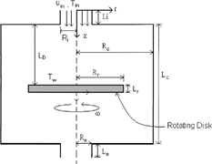
The flow configuration used in this study is shown in . The gas enters the flow field from the inlet, flows over the rotating disk, and out of the chamber from the outlet. The inlet has radius R i and length L i . The radius and length of the chamber are R c and L c , respectively. The rotating disk, with radius R r , length L r , and rotation speed ω, can be thought of as the susceptor on which wafers are placed to grow thin films or deposit silica particles. This rotating disk is located at a distance L D from the top wall of the chamber. The outlet has the same dimension as the inlet. To carry out the flow field computation, the following assumptions were made:
-
The particle phase is dilute so that the particles will not affect the flow field.
-
The flow is steady and laminar due to a low gas flow rate and low disk rotation speed. The gas is assumed to be air with constant physical properties.
-
The rotating disk temperature is assumed uniform throughout the disk with a value of T w .
-
The buoyancy effect on the flow is neglected.
As shown in , the flow field is axisymmetric with respect to the x-axis. However, swirl velocity exists due to disk rotation. The inlet gas temperature is generally lower than that of the susceptor in CVD applications. In waveguide preform manufacturing, the inlet gas flow temperature is higher than that of the disk because a combustion reaction is involved at the inlet. Both the flow and temperature were computed by employing the commercial CFD package FLUENT in which the governing equations are discretized using a finite volume method (CitationFLUENT 1999). In this study, the PISO (pressure implicit with splitting of operators) scheme was chosen for the flow field computation while the QUICK scheme was employed for the temperature calculation. According to the flow configuration, the boundary conditions for the flow and temperature fields were as follows:
-
Inlet: uniform inlet velocity and temperature,
(1)
-
Rotating disk: top and bottom surfaces,
edge surface,(2)
(3)
-
Chamber wall:
(4)
-
Outlet:
(5)
Particle Motion
Because the particle phase was assumed dilute, the Lagrangian approach was appropriate to describe the particle behavior. For submicron particles in a flow field with temperature gradient, the equation of motion for the particles can be written as (CitationHe and Ahmadi 1998)
Results and Discussion
Numerical Parameters
A number of parameters must be specified before carrying out the simulations. Using the inlet velocity and diameter as the reference velocity and length, the inlet flow condition can be characterized by the inlet Reynolds number defined as
In the grid system, denser grids are distributed in the region around the disk to obtain accurate flow simulation results. Using the critical case in this study, i.e., Re in = 137 and Reω = 2466, a number of numerical experiments were performed to determine the grid size that produced grid-independent results. It was found that a grid distribution of 250× 50 produced acceptable results by comparing the velocity and temperature distributions in the region near the rotating disk and were used in all of the simulations presented below.
Silicon particles with 1 μm, 0.1 μm, and 0.01 μm diameters were used in the particle phase in this study. The density and thermal conductivity of the silicon particles were 2330 kg/m3 and 31.2 W/mK, respectively.
Flow Pattern and Temperature Field
shows the typical flow and temperature field results inside the flow domain when Re in = 137 and Δθ = 0.91. The right-hand side in shows the streamlines and isotherms for the Reω = 0 (stationary disk) case, while the left-hand side shows the Reω = 2466 (rotating disk) case. The flow configuration in this study can be viewed as a fluid flow over a sudden expansion section; it impinges on the disk and then flows out of the flow domain through a sudden contraction section. Recirculation zone formation is expected in this type of flow field because of the disk. For the Reω = 0 case, it is found that a smaller recirculation zone exists near the edge of disk in addition to the larger one above the disk. Because the Reynolds number is low, no recirculation zone was found behind the disk. For Reω = 2466 case, the disk rotation effect on the flow is clearly seen. Because of fluid acceleration near the rotating disk, two recirculation zones appear, one in the upper half and the other in the lower half. For the Re in and Reω ranges studied, no flow suction occurred at the outlet due to disk rotation. Note that because the flow configuration involves a sudden expansion inlet section, the flow field characteristics are different from the classical flow solution near an infinite rotating disk (CitationWhite 1991), axial flow impinging on an infinite rotating disk (CitationSong and Hwang 1998), and stagnation-type CVD (CitationVan Santen et al. 2000a, b).
FIG. 2 Flow and temperature fields under the conditions of Reω = 0, Reω = 2466, Re in = 137, and Δθ = 0.91: (a) streamlines, (b) isotherms.
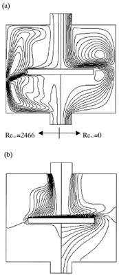
The temperature inside the flow field is represented by the distribution of 19 isotherms with equal increment as shown in . For the Reω = 0 case, the temperature is affected by diffusion and convection due to the inlet gas flow only. This produces a pocket-shaped temperature distribution in the center region of the flow field. In the Reω = 2466 case, the isotherm distribution is different from that of the Reω = 0 case because of the inlet gas flow and rotating disk effects.
Particle Motion
The particle motion in the flow field is presented in this section. Large numbers of particles were released from the inlet with the same velocity as the gas. Their trajectories were computed in the flow field. In , typical particle trajectories with diameters of dp = 1 μm, 0.1 μm, and 0.01 μm for Re in = 137 are presented to address the particle motion characteristics in the flow field. In , particle trajectories with dp = 1 μm under the Reω and Δθ effects are presented. corresponds to the particle trajectories in the isothermal flow field. When the disk is stationary, a small fraction of the particles have the chance to impact and deposit onto the disk. As the disk rotates with Reω = 2466, fluid centrifugal acceleration causes the particles to be swept away from the disk with no chance to impact onto the disk. These particles are either captured by the recirculation zone or escape from the flow field. Particles captured by the recirculation zone have trajectories that closely follow the chamber wall.
FIG. 3 Particle trajectories of dp = 1 μm, Reω = 0 and 2466: (a) Δθ = 0, (b) Δθ = 0.91, and (c) Δθ = −0.91. Re in = 137.

FIG. 4 Particle trajectories of dp = 0.1 μm, Reω = 0 and 2466: (a) Δθ = 0, (b) Δθ = 0.91, and (c) Δθ = −0.91. Re in = 137.

FIG. 5 Particle trajectories of dp = 0.01 μm, Reω = 0 and 2466: (a) Δθ = 0, (b) Δθ = 0.91, and (c) Δθ = −0.91. Re in = 137.

When a temperature gradient exists in the flow field, particle motion will be affected by thermophoretic force. In , particle trajectories with Δθ = 0.91 and −0.91 are presented. For Δθ = 0.91, the thermophoretic force acting on the particles is in the negative x direction. This prevents particles from impacing onto the disk and creates a particle-free zone above the disk, either stationary or rotating. However, no particle penetration into recirculation zone is observed for both stationary and rotating disk cases. This indicates that the upward thermophoretic force is not great enough to drive the particles into the recirculation zone. Note that the particle-free zone size found for the rotating disk case is depressed by the centrifugal acceleration effect. For the Δθ = −0.91 case, a downward thermophoretic force acts on the particles. Comparing , particle deposition is enhanced by the thermophoretic force for both stationary and rotating disk cases. In this situation, particle deposition onto the disk depends on the initial radial location where the particle was released (CitationDavis et al. 1993). Particles released from the region near the center of the inlet will impact onto the disk. Those released far away from the centerline have the chance to escape from the flow field.
In , particle trajectories with dp = 0.1 μm diameter under Reω and Δθ effects are shown. For the isothermal flow shown in , similar particle dynamic behavior as that of dp = 1 μm was found for both stationary and rotating disk cases. There was not much difference in particle trajectory except for the Brownian force effect. In , thermophoretic force influence on the particle trajectories is shown. For the Δθ = 0.91 case, the thermophoretic force drives all particles into the recirculation zone above the disk for both stationary and rotating disk cases. This phenomenon is completely different from that for dp = 1 μm shown in . From the particle trajectory trend, it might be suspected that the center of the recirculation zone is a fixed point in the flow field at which particles remain motionless (CitationBurns et al. 1997). For the Δθ = −0.91 case, as shown in , the thermophoretic force enhances particle deposition onto a stationary or rotational disk. This situation is similar to that of dp = 1 μm as shown in . The deposition rate with dp = 0.1 μm is higher than that for dp = 1 μm by comparing the particle trajectories shown in .
Trajectories for dp = 0.01 μm particles under Reω and Δθ effects are shown in . In the isothermal flow field as shown in the particle trajectories have the same characteristics as dp = 1 μm and 0.1 μm particles, except the increasing Brownian motion effect. Because of random Brownian motion, some particles have the chance to be driven into the recirculation zone for both stationary and rotating disk cases. By comparing the flow streamlines shown in , particles captured by the recirculation zones follow the flow streamlines closely. When Δθ > 0, as shown in , particle-free zones also exist for both stationary and rotating disk cases. Unlike the phenomenon shown in , the thermophoretic force drives some particles into the recirculation zone above the disk while some particles flow out of the flow domain when the disk is stationary. However, all particles are captured by recirculation zone above the disk without escaping from the flow domain when the disk is rotating. For the Δθ < 0 case, as shown in , particle behavior becomes more random because of Brownian motion when the disk is stationary. Particles might deposit onto the disk, chamber wall, and backside of the disk, captured by the recirculation zone, or escape from the flow field. In the disk rotating case, similar particle behavior as when the disk is stationary occurs except that there are no particle depositions onto the chamber wall and disk backside. It can be concluded that Brownian motion is more important than thermophoretic force in controlling particle behavior for very small particles.
Particle-Free Zone Size and Deposition Rate
From the above particle trajectory characteristics, the temperature of the inlet gas flow, rotation speed, disk temperature, and particle size are the important factors that control particle motion in the flow field. With positive Δθ values, a particle-free zone was established for either a stationary or rotating disk. In the case of negative Δθ values, particle deposition was enhanced due to the thermophoretic force. In addition to these parameters, it is believed that the inlet gas flow velocity characterized by Re in also plays an important role in particle dynamics. The value of Re in affects the convection mechanism on the energy transport and consequently influences the thermophoretic force acting on the particles. We defined two quantities to obtain the general features of the particle behavior affected by these parameters. These two quantities are the size of the particle-free zone and the particle deposition rate defined as
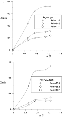
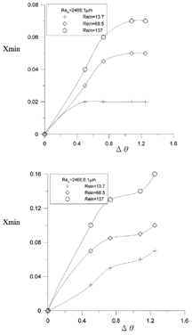
In , the Xmin values as functions of Re in , and Δθ and the particle size are presented when the disk is stationary. The Xmin result for dp = 0.01 μm was not presented because of the random nature of particle trajectories. Determining Xmin for dp = 0.01 μm requires averaged trajectories from a large number of particles (CitationHe and Ahmadi 1998). From , for both cases of dp = 1 μm and 0.1 μm, Xmin increases with the increase in Δθ. Large Xmin values are observed when Re in and dp are small. This implies that thermophoretic force is more significant for a small gas flow rate and small particles. The rotation effect on Xmin is represented in for both the dp = 1 μm and 0.1 μm cases. It was found that Xmin increases with the increase in Δθ; however, the Xmin value is much smaller because of the centrifugal effect. Note that the Re in effect on Xmin is reversed compared to the Reω = 0 case. As shown in , large Xmin values are obtained when Re in is smaller. By examining the temperature distribution near the rotating disk for various Re in , it was found that the temperature gradient decreases when Re in increases. Therefore, the thermophoretic force is weaker such that particles can travel closer to the rotating disk when Re in is small and creates a smaller particle-free zone.
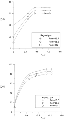
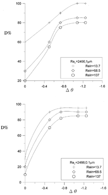
As discussed earlier, particle deposition onto the disk occurs only when Δθ ≤ 0. In , the particle deposition rate as functions of Re in , Δθ, and the particle size are presented when the disk is stationary. The deposition rate increases when |Δθ| increases and decreases when Re in increases. Therefore, a low inlet gas flow rate is suggested for obtaining a higher particle deposition rate. Certain |Δθ| values occur beyond which the deposition rates become constants. A further increase in |Δθ| will not produce an increase in the deposition rate. For example, for the case of Reω = 0, dp = 1 μm, and Re in = 137, a constant deposition rate of 60% can be achieved as Δθ becomes greater than approximately 0.8. In , the rotation effect on the particle deposition rates is shown for particles with dp = 1 μm and 0.1 μm. It was found that particle deposition is enhanced by the disk rotation. The deposition rate was also found to increase as the inlet gas flow rate became lower. Similar to Reω = 0 cases, deposition rates became unchanged as |Δθ| became greater than certain values for various Re in . For dp = 1 μm and Re in = 137, 85% deposition rate can be achieved as |Δθ| is greater than 1. For dp = 0.1 μm and Re in = 137, constant deposition rate with value of 80% can be found when |Δθ| is greater than 0.8.
Conclusion
In this study, submicron particle dynamics in a flow field involving a rotating disk, temperature gradient, and different flow rate were numerically analyzed. The Lagrangian model was used to track particle trajectories with diameters of 1 μm, 0.1 μm, and 0.01 μm. Nondimensional flow rate Re in , disk rotation speed Reω, and the temperature difference Δθ effects on particle dynamics in this flow field were addressed.
In the case of positive Δθ, which is the contaminant particle control application in the CVD process, a particle-free zone exists above the disk due to the upward thermophoretic force. Particles with diameters of 1 μm and 0.1 μm can never deposit onto the disk or chamber wall for both stationary and rotating disks. These particles were either captured by the recirculation zones or escaped from the flow field. Particles with 0.01 μm diameter deposition onto the disk or chamber wall was possible due to the random Brownian motion. By defining the particle-free zone size Xmin as the minimum distance between trajectory of a particle released from the inlet location (x, r) = (0,0.01 R i ) and the disk, it was found that Xmin increased with the increase in Δθ but decreased with the increase in Re in when the disk was stationary. For the rotating disk case, Xmin was found much smaller compared to the stationary disk case and increased with the increases in Δθ and Re in .
For the case of negative Δθ, which is the application in the silica particle deposition process used in the waveguide preform manufacturing process, particle deposition was found enhanced by the thermophoretic force for both stationary and rotating disk cases. Using the percentage of particles deposited onto the disk to quantify the deposition rate for 1 μm and 0.1 μm particles, it was found that the deposition rate was enhanced by disk rotation. Deposition rates were found to achieve constant values when the temperature differences between the inlet gas and disk were beyond certain values for both stationary and rotating disk cases. Larger particle deposition rates were obtained when the inlet gas flow rate was low. For the 0.01 μm particles, Brownian motion was more important than thermophoretic force in controlling particle behavior.
REFERENCES
- Burns , T. J. , Davis , R. W. and Moore , E. F. 1997 . Dynamical Approach to Particle Transport Modeling in Dilute Gas-Particle Flows with Application to a Chemical Vapor Deposition Reactor . Aerosol Sci. Technol. , 27 : 1 – 21 .
- Davis , R. W. , Moore , E. F. and Zachariah , M. R. 1993 . Numerical Modeling of Particle Dynamics in a Rotating Disk Chemical Vapor Deposition Reactor . J. Crystal Growth , 132 : 513 – 522 .
- Fotiadis , D. I. and Jensen , K. F. 1990 . Thermophoresis of Solid Particles in Horizontal Chemical Vapor Deposition Reactors . J. Crystal Growth , 102 : 743 – 761 .
- FLUENT . 1999 . User Guide, v5.5 , Lebanon, NH : Fluent Inc. .
- He , C. and Ahmadi , G. 1998 . Particle Deposition with Thermophoresis in Laminar and Turbulent Duct Flow . Aerosol Sci. Technol. , 29 : 525 – 546 .
- Hong , K. H. and Kang , S. H. 1998 . Three-dimensional Analysis of Heat Transfer and Thermophoretic Particle Deposition in OVD Process . Int. J. Heat Mass Transfer. , 41 : 1339 – 1346 .
- Jensen , F. J. , Einset , E. O. and Fotiadis , D. I. 1991 . Flow Phenomena in Chemical Vapor Deposition of Thin Film . Ann. Rev. Fluid Mech. , 23 : 197 – 232 .
- Kawachi , M. 1990 . Silica Waveguides on Silicon and Their Application to Integrated-optic Components . Optical Quantum Electronics , 22 : 391 – 416 .
- Kleijn , C. R. 2000 . Computational Modeling of Transport Phenomena and Detailed Chemistry in Chemical Vapor Deposition-a Benchmark Solution . Thin Solid Films , 365 : 294 – 306 .
- Oh , M. D. , Yoo , K. H. and Myong , H. K. 1996 . Numerical Analysis of Particle Deposition onto Horizontal Freestanding Wafer Surfaces Heated or Cooled . Aerosol Sci. Technol. , 25 : 141 – 156 .
- Oh , E. K. and Kim , S. G. 1996 . Modeling and Measurement of Aerosol Deposition on a Heated Substrate . J. Aerosol Sci. , 27 : 1143 – 1154 .
- Opiolka , S. , Schmidt , F. and Fissan , H. 1994 . Combined Effect of Electrophoresis and Thermophoresis on Particle Deposition onto Flat Surfaces . J. Aerosol Sci. , 25 : 665 – 671 .
- Pui , D. Y. H. , Ye , Y. and Liu , B. Y. H. 1990 . Experimental Study of Particle Deposition on Semiconductor Wafers . Aerosol Sci. Technol. , 12 : 795 – 804 .
- Schmidt , F. , Fissan , H. and Schmidt , K. G. 1996 . Transport of Submicron Particles From a Leak to a Perpendicular Surface in a Chamber at Reduced Pressure . J. Aerosol Sci. , 27 : 739 – 750 .
- Schultz , P. C. 1980 . Fabrication of Optical Waveguides by the Outside Vapor Deposition Process . Proc. IEEE , 68 : 1187 – 1190 .
- Song , C. G. and Hwang , J. 1998 . Particle Deposition on a Rotating Disk in Application to Vapor Axial Deposition (VAD) . Process. J. Aerosol Sci. , 29 : 99 – 114 .
- Strogatz , S. H. 1994 . Nonlinear Dynamics and Chaos , New York : Addison-Wesley Publishing Company .
- Van Santen , H. , Kleijn , C. R. , Harry , E. A. and van den Akker , H. E. A. 2000a . On Turbulent Flows in Cold-wall CVD Reactors . J. Crystal Growth , 212 : 299 – 310 .
- Van Santen , H. , Kleijn , C. R. , Harry , E. A. and van den Akker , H. E. A. 2000b . Symmetry Breaking in a Stagnation-flow CVD Reactor . J. Crystal Growth , 212 : 311 – 323 .
- White , F. M. 1991 . Viscous Fluid Flow , 2nd ed. , New York : McGraw Hill, Inc. .
- Ye , Y. , Pui , D. Y. H. , Liu , B. Y. H. , Opiolka , S. , Blumhorst , S. and Fissan , H. 1991 . Thermophoretic Effect of Particle Deposition on a Free Standing Semiconductor Wafer in a Clean Room . J. Aerosol Sci. , 22 : 63 – 72 .
