Abstract
To determine the airborne emissions that occur when conventional munitions are destroyed by open burn/open detonation (OB/OD), munitions shots were carried out in a large underground (4650 m3) chamber. Carrying out the tests in a chamber allows the total emissions to be measured, which is not possible in open-air testing. We report here the development of an instrument to measure the time-dependent mass concentration and aerosol size distribution of respirable aerosols (< 10 μ m) from detonations of artillery projectiles in the underground chamber. The instrument incorporates an on-line diluter and real-time cascade impactor for aerosol monitoring. Design, flow modeling, construction details, and results from the instrument are given.
Particulate emissions from detonations of twenty four 155 mm artillery projectiles, with a total of 377 lbs net explosive weight, were monitored. Aerosol measurements from the two duplicate tests were very similar. Aerosol mass concentrations showed rapid decreases from 37,000 and 65,000 μ g/m3 for the first samples for the two tests, 14 and 17 min after detonation, to near 20,000 μg/m3 at 20 min after each detonation. Thereafter the concentration decreased less rapidly to several thousand μg/m3 at 90 min after the detonation. Aerosol mass concentrations peaked in the 0.3–0.6 μm diameter range during the first 30–60 min of sampling and shifted to smaller particles (< 0.3 μm) toward the end of the sampling period (90 min) as turbulence decreased in the detonation chamber and large particles settled out.
The data were highly reproducible between the two tests, indicating that the instrument performed satisfactorily. The data will be used to help determine the characteristics of dust emitted from OB/OD shots for munitions demilitarization and will provide a baseline for designing future studies to monitor the airborne emissions from full-scale open-air munitions demilitarization tests.
INTRODUCTION
The Los Alamos Aerosol Sampling System (LAASS) was developed to measure the aerosol mass concentration and size distribution of particulate emissions from contained detonations of military munitions as a function of time. Measurements from contained detonations are used to estimate the airborne emissions that take place in open-air detonations (ODs). ODs are the preferred method for the Department of Defense (DoD) to destroy excess conventional munitions, propellants, and energetic materials. To access the environmental impacts of such OD of munitions, the Environmental Protection Agency (EPA) requires a report of the airborne emissions, including particulate and gaseous species. These data are needed to determine the potential hazard to workers and the public that may result from OD demilitarization activities. In addition, improved knowledge of the emissions from OD processes will help develop more efficient methods of demilitarization of energetic materials. In order to determine these emissions, large-scale tests were carried out in an underground chamber in the Department of Energy's Nevada Test Site (NTS) as part of the Joint DOE/DoD Joint Demilitarization Technology (JDT) Program, Conventional Munitions Demilitarization Experiments, sponsored by the Defense Ammunition Center (DAC). These tests seek to obtain quantitative measurements of the airborne emissions from full-scale military munitions that can, at present, only be obtained from measurements of contained detonations. In addition, a program goal is to develop instrumentation that are applicable to monitoring airborne emissions from full-scale open-air demilitarization activities that will be carried out in the future. A full report of the program of underground munitions detonations is contained in a report by CitationWatkins et al. (2000).
Two detonations of 155 mm artillery projectiles (twenty four shells each) were carried out in a large (4650 m3) sealed chamber in a tunnel at the Department of Energy's NTS during July and August 1999. The LAASS collects aerosol samples after the detonation by drawing aerosol-laden gas through the detonation chamber barrier into two sampling systems. One system (cascade impactor) dilutes the aerosol sample and measures the mass concentrations (μ g/m3) of the respirable aerosols between 0.1 to 10 μm aerodynamic diameter. The other system collects a single aerosol sample for subsequent electron microscopy analysis to determine the size distribution, morphology, elemental composition, and crystallinity of phases present in the aerosol. Reported here are the instrument design, flow modeling, and a summary of the results from the cascade impactor.
DESCRIPTION OF THE LAASS
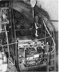
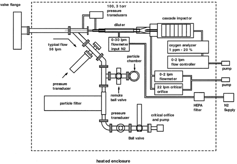
The LAASS is mounted on the low-pressure side of the detonation chamber barrier as shown in . shows a schematic of the system. The system is attached to a high-pressure and temperature barrier valve (valve flange) that isolates the sampling system from the test chamber. A 20 mm internal diameter sampling probe penetrates through the barrier and extends 0.6 m into the chamber to sample air away from the barrier wall. After the detonation the barrier valve is opened within 9 min of the detonation time. For these tests, the valve was opened when the chamber pressure and temperature were below 18 PSIA and 85°C, respectively. Samples were obtained for most of the period between opening of the sample valve to the end of the sampling period typically 90 min after the detonation.
During sampling operations, chamber air is drawn into the “high-flow” arm of the sampling system at a flow rate of 56 liters per minute (lpm). In the high-flow arm angles down at a 45-degree angle from the main sampling tube. The sample gas passes through a particle filter, pressure transducer, ball valve, critical orifice (CO), and air-driven vacuum pump. The critical orifice controls the flow through the high-flow arm. The LAASS flow system is heated to 50°C to prevent water condensation in the system. The aerosol sample collection chamber (particle chamber) consists of a 50 mm diameter by 100 mm long volume that was evacuated prior to the test. The pressure level of the collection chamber was varied depending on the quantity of aerosols to be collected on the TEM grids. Since we were interested in studying the morphology, elemental composition, and crystal structure of the particles rather than the absolute quantity of the particles, the results of the analyses did not depend on the vacuum level in the collection chamber. Transmission electron microscope (TEM) “grids” were attached to the bottom of the sample chamber. After the sample flow was established in the high-flow arm, the remote ball valve was opened between the high-flow arm and the chamber, drawing a sample into the particle chamber. Aerosols settle by gravity onto the TEM collectors for later analysis. The TEM grids then contain a “snapshot” of the aerosol population at one time during the sampling period.
A portion of the main sample flow is drawn into the diluter, with a nominal flow rate of 0.25 lpm, from the high-flow arm through a small diameter stainless steel tube. The flow through the tube is monitored by measuring the flow-induced pressure differential across the tube using two differential pressure transducers, with ranges of 100 torr and 3 torr. The low-range pressure transducer can be isolated by remotely controlled valves to avoid over-ranging the transducer. The aerosol sample from the diluter inlet tube is mixed with nitrogen in the diluter that consists of a porous stainless tube (Mott Metallurgical Corporation) that is coaxial with the inlet tube. The actual dilution ratio is determined by the oxygen analyzer downstream from the diluter. The nitrogen dilution gas is filtered with a high efficiency particulate air (HEPA) filter with pore size of 0.3 μm, and an “absolute” filter with pore size below 0.1 μ m, and heated to eliminate water condensation in the sampling system. The nitrogen flow is controlled by a mass flow controller. The diluted sample gas passes into a skimmer where 1 lpm is drawn into the cascade impactor. The excess diluted sample is drawn off with the flow controlled by a 22 lpm critical orifice and 0–2 lpm flow controller. The sample gas, after passing through the cascade impactor, which removes the aerosols and measures their mass concentration, flows through an oxygen analyzer that provides a real time readout of the oxygen concentration of the exhaust gas from which the actual dilution ratio of the system is derived.
Operation of the LAASS is controlled by a multilevel computer system. A programmable logic controller (PLC), located adjacent to the LAASS flow system, controls the operation of the valves and flow controllers and collects data from the impactor and other sensors. The PLC communicates over fiber optics with a computer located in the portal instrumentation building located adjacent to the tunnel portal approximately 240 m from the LAASS.
The cascade impactor, a customized California Measurements system, separates particles by aerodynamic diameter into 7 size bins with particle separation points of 10, 5, 2.5, 1.2, 0.6, 0.3, and 0.12 μ m. Particles larger than the separation points are successively removed as the airstream passes through the collector. Particle mass at each stage in the impactor is measured by depositing the particles onto quartz crystal microbalances (QCMs) and monitoring their change in frequency versus time. QCM frequencies are recorded every second by the LAASS. The change of frequency with time at the set flow rate provides a measurement of aerosol mass concentration (μ g/m3) for each aerosol size range. Masses in individual size ranges are summed to produce measurements of the mass of particles less than 10 μ m (PM10) and less than 2.5 μm (PM2.5), which are of interest for OB/OD emissions monitoring.
The oxygen monitor is a customized version of a ceramic oxygen sensor used to monitor oxygen concentrations in combustion exhaust streams. The system utilizes an electrochemical cell to monitor oxygen concentrations between the parts-per-million (ppm) range and atmospheric levels. Our system was built as a sealed unit to operate at 1 lpm to match the flow rate in the cascade impactor. Variations in flow rate over a several liters-per-minute range did not effect the readings. The oxygen concentrations measured were typically 5000 ppm. The nitrogen dilution gas had oxygen concentrations below 100 ppm. The pressure within the sensor was monitored and used to correct the oxygen concentration for pressure effects. Dilution ratios were determined by taking the oxygen concentration measured by the oxygen monitor to the oxygen concentration in the test chamber, obtained by a collaborator who measured gas concentrations during the tests.
MODELING AEROSOL TRANSPORT AND FLOW THROUGH THE LAASS
Particle transport through the barrier and into the samplers is a key design element in the LAASS. The aim is to transport 100% of particles less than 10 μm in aerodynamic diameter but not to transport significant quantities of larger particles to avoid overwhelming the samplers. Transport calculations were carried out to optimize the aerosol transport efficiency of the various parts of the LAASS, including the sampling probe inside the barrier, the sampling tube to the diluter, and the skimmer leading to the cascade impactor. Calculations were performed using the Deposition 4.0 for Windows program (CitationMcFarland 1999) and the Aerosol Sampling and Transport Efficiency Calculation (ASTEC) program (CitationYamano and Brockmann 1989). These modeling tools include aerosol loss by aspiration and inlet deposition, gravitational settling, diffusion, turbulent inertial deposition, thermophoresis, and inertial deposition.
The models do not include the effects of particle charge on aerosol transport and collection. There has been an experimental study that indicates that the particle collection efficiency in a cascade impactor is affected by the charge of the incoming aerosol (CitationHorton et al. 1992). The charge on the aerosols in the detonation chamber is not known, however, and we did not implement a method of measuring or neutralizing particle charge in the aerosol collection system. We were concerned about possible particle loss in a particle charge neutralization system. In future studies, we plan to incorporate a particle neutralization system in the design, coupled with an instrument to measure actual particle transmission through the system with and without a particle neutralizer.
The degree of turbulence of the gas in the detonation chamber is not measured in these studies. Thus there is not a well-defined gas velocity for use in designing the sampling probe. The optimum sampling into the LAASS and transport through the 2 m long sampling probe is a balance between efficient aspiration and sampling by the probe and efficient transport of the sample to the diluter inlet tube. For optimum sampling into the probe, we used CitationDavies (1968) sampling criteria for calm air conditions, which established two conditions for representative sampling:
For our 20 mm internal diameter (ID) sampling probe and 56 lpm flow rate, the sampling velocity is 297 cm/s. Terminal velocities for 1 and 10 μ m unit density particles are 3.5 × 10− 3 and 3.1 × 10− 1 (cm/s), respectively, resulting in Stokes numbers for the inlet of 5.2 × 10− 6 and 3.4 × 10− 2. The velocity ratios for 1 and 10 μ m particles are 1.2 × 10− 5 and 1.0 × 10− 3. For the largest 10 μ m particles the Davies criterion is slightly exceeded in Stokes number but is met for smaller particles. In all cases the velocity ratios are below the Davies criterion. In view of the uncertainty in turbulence in the detonation chamber we adapted the above probe geometry and flow rates for sampling.
Transport of the sample through the 200 cm long, 20 mm diameter sampling probe, which delivers the sample to the diluter inlet, was optimized by varying the flow rate and tube internal diameter. The aerosol loss was calculated using the ASTEC aerosol transport code. Because our sampling system did not have any bends or crosses and the internal surface of the tubing was smooth, bends and surface roughness were not included in the efficiency calculations. For our inlet and tubing geometry, losses were dominated by gravitational settling in the horizontal sampling tube. Total sampling and transport efficiencies were greater than 90% for particles less than 7 μ m. Transport efficiency by gravitational settling for 10 μ m particles was calculated to be 86%. The tube Reynolds number for the flow is about 4500, close to the nearly full turbulent flow regime.
The length and diameter of the diluter inlet tube are a balance between aerosol loss and plugging considerations, which favor large diameter and short length, against obtaining a large enough pressure differential across the tube to allow accurate flow measurements. For the final system a tube of diameter 0.155 cm ID by 20 cm was chosen. With a thin tubing wall of less than 1 mm with tapered entrance and exit ends the capillary satisfies the “thin wall criterion” for nozzles (CitationBelyaev and Levin 1972). With this tubing size the pressure difference is 0.75 torr at 0.25 lpm flow. The tubing sampled the high flow aerosol stream isokinetically at this flow rate.
CitationMorewitz (1982) established a plugging criterion based on the integral aerosol mass flowing through a tube and the tube diameter:
For our diluter input tube (d = 0.155 cm) the minimum plugging criterion is 27 mg. For sampling conditions of 300 mg/m3 aerosol concentration and 0.25 lpm flow rate for 1 h, the total aerosol mass flow through the tube is 4.5 mg, well below Morewitz's plugging criteria. In practice, after a test the inside of the tube was found to be clean with no evidence of plugging.
The flow through the diluter inlet tube operated in the laminar flow regime with a Reynolds number of about 260. Aerosol transport through the capillary was modeled using the ASTEC program by modeling the tube as a short probe directly attached to a horizontal tube of the same diameter. Inlet deposition efficiencies for 5 μ m and 10 μ m particles were 90% and 75%, respectively. For the remainder of the tube, losses were dominated by gravitational settling, with transport efficiencies of 80, 90, and > 99% for 10, 7, and 1 μm particles, respectively.
The diluter in our system was designed to reduce the particle concentration and decrease the dew point and temperature fluctuations of the sampled gas. Reducing the dew point prevents water condensation in the cascade impactor. Controlling temperature fluctuations in the diluted gas is important since temperature variations can change the frequency of the QCMs in the cascade impactor used to measure particle mass. Our diluter was designed to have a variable dilution ratio of 10 to 100 with a nominal dilution ratio of 30. We incorporated several design features in the diluter; real-time measurement of all of the flows, directly measuring the sample flow into the diluter, and on-line measurement of the dilution ratio of the sample delivered to the cascade impactor.
Several methods have been used in previous designs of diluters. CitationGuichard (1982) used a combination of a sample capillary and porous media or fine grid to control the sample and dilution flows, respectively. Changes in the pressure differential across the diluter changes both flows simultaneously, thereby reducing fluctuations in dilution ratios. CitationBrockmann et al. (1984) used the flow-induced pressure differential across a capillary to control the sample flow and controlled the primary and secondary dilution flows to achieve dilution ratios of 300 to 4000 for ultrafine (< 0.1 μm) aerosols. CitationWu and Flagen (1987) used a two-stage diluter, the first using a sintered tube to introduce a dilution gas to the primary aerosol flow, followed by a second dilution stage that used filtered gases, drawn from the first dilution stage, to achieve dilution ratios of 2000. Input flows or dilution ratios were not monitored directly. More recently, CitationDermott (1997) diluted ultrafine aerosols by matching the velocity of the aerosol-laden gas to the velocity of the dilution gas in a tube to dilute ultrafine aerosols and reduce the concentration of reactive gases prior to aerosol measurements. Our system uses a combination of techniques developed by these authors including measuring the pressure differential across the input capillary used by CitationBrockmann et al. (1984), use of a sintered tube as by CitationWu and Flagan (1987), and employing a skimmer to draw off a sample for analysis, as employed by CitationDermott (1997).
For our system, at the exit of the diluter 1 lpm of diluted sample is drawn off from the center of the flow into the cascade impactor. The remainder of the diluter exhaust flow passed through a 90 degree bend, is filtered, and then passes through a critical orifice (22 lpm) with a 0–2 lpm flow controller in parallel (see ). The extraction nozzle to the impactor is 0.51 cm in diameter and samples the diluter flow isokinetically in the laminar flow regime with a Reynolds number of about 320. The modeled total efficiencies of sampling nozzle and tube are 80, 95, and 99% for 10, 5, and 1 μm particles, respectively.
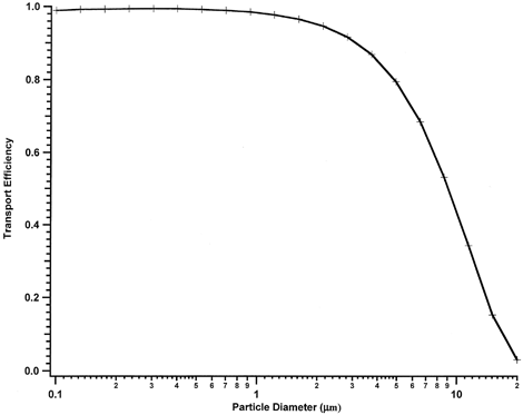
The calculated overall transport efficiency of the LAASS, from the sampling probe in the detonation chamber to the cascade impactor, is shown in . Transport efficiency is greater than 90% for particles less than 3 μ m and greater than 80% for particles smaller than 5 μ m. Transport efficiency drops to 44% for 10 μ m particles. The mass concentrations reported here are systematically low, using the calculated efficiencies, by less than 10% for particle sizes below 2.5 μ m in diameter, about 15% low in the 2.5–5 μ m size range, and up to 35% low in the 5–10 μ m size range, assuming a uniform mass distribution of particles up to 10 μ m. For the size distributions measured, which were dominated by submicron particles, the error is considerably less.
SYSTEM FLOW CALIBRATIONS AND OXYGEN SENSOR CALIBRATIONS
All system flows were calibrated individually using a dry “bubble” flow meter with the system operating under the same conditions as those which occurred during a test. The flow through the inlet tube to the diluter was also calibrated by measuring flow versus pressure differential across the tube. The calibrations were used to establish “set points” for the mass flow controllers during sampling.
Calibration of the oxygen monitor was carried out using custom gas mixtures at concentrations of 0.1, 0.2, and 1% oxygen in nitrogen. For the calibrations, each standard oxygen mixture was introduced into the diluter nitrogen inlet at a flow rate to establish a small flow out of the diluter inlet tube with the diluter exhaust and cascade impactor flows operating at their normal set points. The pressure at the oxygen sensor was monitored during the calibrations and used to correct the oxygen readings during the tests.
LAASS OPERATION DURING SAMPLING
Operation of the LAASS requires following a specific sequence of operations to provide accurate aerosol concentrations. Prior to detonation of the munitions, the system is turned on and nitrogen flow established in the diluter such that there is a small nitrogen flow out of the diluter inlet tube. This small outward flow ensures that background aerosols do not enter the diluter or impactor. The frequencies from the quartz crystal microbalances in the cascade impactor were monitored to establish aerosol-free frequency baselines. In all cases the frequency drift was less than 1 Hz/min. A slow negative drift in frequency for a QCM in the cascade impactor can result in a reported negative concentration of aerosols in a size range with low aerosol concentrations.
After the munitions were detonated, the temperature and pressure in the test chamber are monitored. The peak temperatures and pressures for these tests reached 120°C and 25 PSIA, respectively. The opening sequence for the LAASS is started within 6 min of the detonation. The high-pressure valve to the detonation chamber is opened and flow established in the high-flow arm to transport the sample through the sampling probe from the chamber. After the flow through the high-flow arm is established, an aerosol sample is taken by opening the remote ball valve between the aerosol collection chamber and the high flow arm.
To transport aerosol samples into the diluter and cascade impactor, sample flow into the diluter is adjusted by balancing the nitrogen flow into the diluter and the diluter exhaust flow while monitoring the pressure differential across the diluter inlet tube between the high-flow arm and the diluter. The diluted sample flow into the cascade impactor is then adjusted using the flow controller behind the impactor. The dilution ratio through the system is monitored using the oxygen monitor downstream from the impactor. Aerosol concentrations are derived from the time rate of change of cascade impactor frequencies. To ensure that the sample flow into the diluter was constant during the sampling period the diluter exhaust flow was automatically regulated by “locking” the diluter exhaust flow to the pressure differential across the diluter input tube. This lock was established by a software loop within the PLC. The cascade impactor flow was held constant throughout the sampling period.
Flows into and out of the diluter control the dilution ratio and hence the concentration of aerosols delivered to the cascade impactor. The diluter can operate over a dilution range of about 10 to 100. The nominal dilution ratio is about 30. It is optimal to operate the diluter inlet tube under isokinetic conditions to minimize aerosol sample loss in the tube. The sample flow into the cascade impactor can be “turned off” by reducing the setting on the mass flow controller downstream from the impactor. Under these conditions nitrogen flows out of the diluter through the diluter sampling tube and into the high flow sampling arm. Operation of the LAASS allows significant flexibility in operation, depending on the concentration of aerosols present in the chamber.
RESULTS
In the tradition of underground tests at the NTS, each test was given a name as part of a test series; in this case the theme was pirate names. The two tests reported here are Blackbeard and Lafitte, which were duplicate tests with the same number and configuration of the shells during the shot. For the Blackbeard test, samples were collected continuously while for the Lafitte test sampling was interrupted at intervals to obtain background aerosol-free readings from the impactor QCMs. Interruption of the particle monitoring allowed the particle-free drift of the QCMs to be measured, resulting in more accurate particle concentrations. The interruption of the particle mass measurements had no affect on subsequent measurements, as the high sample flow was maintained throughout each test. Blackbeard sampling was interrupted to rebalance the dilution nitrogen gas flow into the diluter.
Blackbeard Test
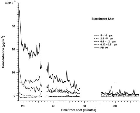
For this test the shells were laid out horizontally on a bed of clean gravel in two rows with a donor charge on each shell. The aerosol mass concentrations for the Blackbeard test are shown in . This and the other concentration figures show the PM10 mass concentrations as well as the concentrations in the size ranges 5–10 μ m, 2.5–5 μ m, 0.6–1.2 μ m, and 0.12–0.3 μ m. Other size ranges, while measured, are not shown in the figures for clarity. PM2.5 concentrations were very similar to the PM10 concentrations. The PM2.5 concentrations can be derived by comparing the 5–10 μ m and 2.5–5 μ m concentrations to the PM10 concentrations shown. The concentrations peak near 37,000 μg/m3 for both PM2.5 and PM10 at 18 min after the shot and then decrease rapidly thereafter. Concentrations fall to less than 2000 μ g/m3 at 70 min after the shot. Gaps in the data occur during the times when the nitrogen flow was being readjusted. This occurs when the 0–2 lpm mass flow controller at the exhaust of the diluter approaches the end of its range. To bring the flow back to the optimum control set point, the nitrogen flow is increased to “turn off” the diluter by flowing nitrogen out of the diluter inlet. The flows are then adjusted and the set points reestablished. The exhaust 0–2 lpm flow is then again “locked” to the diluter inlet pressure differential, and hence flow, into the diluter inlet. Data from the impactor QCMs are again taken for analysis.
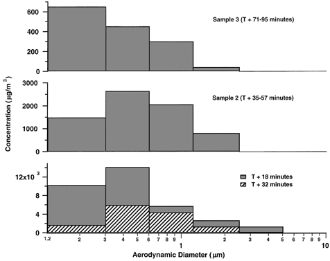
Aerosol size distributions versus time are shown in . The size distribution at the start of sampling (18 min) is dominated by submicron aerosols. Between 18 and 32 min, the smallest size fraction, 0.12–0.3 μm, shows a rapid decrease in concentration due to rapid coagulation at the high particle concentrations in this size regime. At longer times, for sample 2 and 3 (35–57 and 71–95 min, respectively), the total concentration decreases. Larger particles settle out in the chamber, resulting in a more rapid fall in concentration of large particles relative to small particles. By the last sample period small particles, 0.12–0.3 μ m, dominate the particle mass distribution.
Lafitte Test
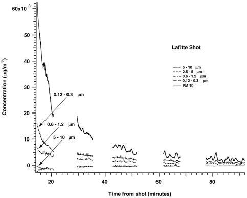
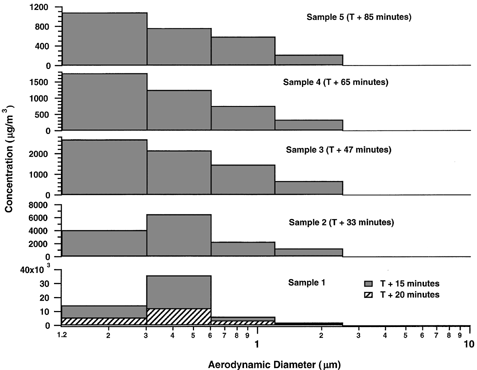
The Lafitte test was a duplicate of the Blackbeard test using the same configuration and number of shells. The aerosol concentrations are shown in . Sampling for the Lafitte test was started 3 min sooner than the Blackbeard test; 14 min versus 17 min for the Blackbeard test. The initial aerosol concentrations were correspondingly greater, with the PM2.5 and PM10 concentrations reaching 65,000 μ g/m3. PM2.5 and PM10 concentrations fall to less than 10,000 μ g/m3 after 45 min. The Lafitte aerosol size distributions as a function of time are shown in . As in Blackbeard, aerosols between 0.3 and 0.6 μm dominated the early (< 33 min) aerosol concentration. Later samples (> 33 min) show a shift in size distribution to smaller sizes as larger particles settle out within the chamber. The smallest particles (< 0.3 μm) dominate the aerosol mass as concentrations decrease.
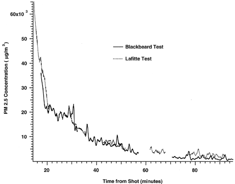
A comparison of the aerosol concentration data from the Blackbeard and Lafitte tests is shown in . The concentrations versus time for the two tests are very similar, both at the early time (< 20 min), where the concentration is falling rapidly, and for later sampling times.
DISCUSSION AND CONCLUSIONS
The LAASS operated successfully for the two munitions shots and obtained data on aerosol size distributions in the respirable size fraction (< 10 μ m). For the Blackbeard and Lafitte tests a sharp decrease in aerosol concentration, to 20,000 μ g/m3, was seen from the start of sampling to 20 min after the shot with a slower decrease in aerosol concentration to ∼3,000 μ g/m3 after 80 min from shot time. Aerosol concentrations and size distributions were very similar for these two tests, pointing to good reproducibility of the munitions shots and aerosol measurements. The good reproducibility of the data gives us good confidence in our ability to see changes in emissions from munitions if the configuration of the munitions in the detonation chamber or the type of munitions is changed.
Acknowledgments
The author would like to thank the sponsor of the work, the Defense Ammunition Center in McAlester, OK, Mr. J. Wheeler, Director, for their support and guidance during the program.
REFERENCES
- Belyaev , S. P. and Levin , L. M. 1972 . Techniques for Collection of Representative Aerosol Samples . J. Aerosol Sci. , 5 : 325 – 338 .
- Brockmann , J. E. , Liu , B. Y. H. and McMurry , P. H. 1984 . A Sample Extraction Diluter for Ultrafine Aerosols . Aerosol Sci. Technol. , 1 : 441 – 451 .
- Davies , C. N. 1968 . The Entry of Aerosols into Sampling Tubes and Heads . Br. J. Appl. Phys. (J. Phys. D), Ser. 2 , 1 : 921 – 932 .
- Dermott , W. T. 1997 . A Reactive Gas Diluter for Measuring Nanometer-Size Particles . Aerosol Sci. Technol. , 26 : 285 – 288 .
- Guichard , J. C. 1982 . Some Uses of a Diluter for Aerosols . Sci. Total Environ. , 23 : 273 – 282 .
- Horton , K. D. , Ball , M. H. E. and Mitchell , J. P. 1992 . The Calibration of a California Measurements PC-2 Quartz Crystal Cascade Impactor (QCM) . J. Aerosol Sci. , 23 : 505 – 524 .
- McFarland , A. R. 1999 . Deposition 4.0 for Windows . Available from Professor A. R. McFarland, Texas A&M University, College Station, TX 78843
- Morewitz , H. A. 1982 . Leakage of Aerosols from Containment Buildings . Health Phys. , 42 ( 2 ) : 195 – 207 .
- Wu , J. J. and Flagan , R. C. 1987 . Onset of Runaway Nucleation in Aerosol Reactors . J. Ap. Phys. , 61 : 1365 – 1371 .
- Watkins , B. C. , Pruneda , C. O. , Velsko , C. A. , Moeller , A. E. , Williams , S. M. , Stephens , J. R. , Gray , W. C. , Thomas , W. C. , Lipkin , J. , Peabody , R. L. , Roberts , H. , Boehm , R. F. , Coates , G. , Gonzles , R. and Kwak , S. W. 2000 . Department of Defense/Department of Energy Joint Demilitarization Technology Program, Phase III Demonstrations, Detonation of Conventional Weapons: 155 mm High-Explosive M107 Projectiles, UCRL-ID-140072 .
- Yamano , N. and Brockmann , J. E. 1989 . “ Aerosol Sampling and Transport Efficiency Calculation (ASTEC) and Application to Surtsey/DCH Aerosol Sampling System ” . In Sandia National Laboratories, NUREG/CR-5252 SAND88–1447 R3, R4, R7
