Abstract
The particle rebounding characteristics of a gas–particle flow over a cylindrical body is investigated. With the aid of both computational and experimental approaches, the mean particle flow patterns, comprising both incident and rebound particles resulting from the impact of particles on a curved wall surface, are examined. In the experimental investigation, a two-dimensional Laser Doppler Anemometry (LDA) technique is used in the immediate vicinity of the body surface to measure the instantaneous incident and rebound particle velocities. The Reynolds-Averaging Navier-Stokes equations are solved for the continuum gas phase, and the results are used in conjunction with a Lagrangian trajectory model to predict the particle-rebound behavior in the immediate vicinity of the cylindrical wall. The computational observations, also confirmed through experiments, reveal a particle rebound zone where the mean particle flow pattern is significantly modified due to the contribution of the rebound particles during the process of particle–wall impact interaction. This particle rebound zone is found to be a function of mainly the Stokes number (particle inertia), and to a lesser extent on the fluid Reynolds number (gas flow condition), except for high gas flow velocities and restitution coefficients (particle-wall impact characteristics). Analysis of the effect of the above-mentioned parameters on the rebounding particle flow characteristics and their interrelationship has provided a better understanding of the behavior of particle flow impinging on a solid wall body. The beneficial contributions of the experimental and computational approaches in their ability to better quantify the particle–wall impact interaction phenomena present additional foundational investigations that could be further undertaken to better comprehend the particle behavior in curved wall surfaces. Such invaluable information has direct applications to industrial devices such as commercial heat exchangers and inertial impactors.
INTRODUCTION
Solid-particle impact interaction with material wall surfaces continues to receive considerable attention in the scientific and technical communities. Enormous interest on this phenomenon derives primarily on the problem's fundamental nature. A great deal of concerted research efforts and resources have been allocated to comprehend better the particle impact characteristics. Through these probing investigations, significant improvements to prolong the operational longevity of industrial devices that are constantly subjected to the rigorous bombardment of solid particles can be achieved. Some typical examples of such devices are the movement of dusty gas flow in coal combustion equipment and heat exchangers. Through careful monitoring of these devices by regular maintenance and strict operational conditions, it is hoped that any catastrophic consequences that may be caused by significant erosion damage are avoided (CitationFan et al. 1997). In the aerosol industry, inertial impactors are used extensively to measure aerosol size distribution and to collect samples for further chemical analysis (CitationTsai and Cheng 1995). Many different physical methods, for example, impaction, impingement, filtration, and electrostatic precipitation, are commonly used to sample particles from an air environment actively (CitationGrinshpun et al. 1997). Because of the many industrial applications, it is therefore rather important that an in-depth investigation is performed to understand better the near-wall behavior of the hydrodynamics of the fluid and particle motion affecting the mechanism of the corrosive wear and particle collection efficiency of these industrial devices.
In their earlier work, CitationTu et al. (1998) reported both numerical and experimental studies for turbulent gas–particle flow in an in-line tube bank. Their objectives were to provide valuable experimental data to evaluate the numerical model based on an Eulerian-Eulerian formulation for the turbulent particle-laden gas flow in tube banks configuration (CitationTu and Fletcher 1995a, b). Although the Eulerian-Eulerian model, with its economical computational benefits and proven efficiency, has contributed much success to the numerical predictions, a closer examination revealed that there were still fundamental flaws associated with the formulation. The problem concerning the particle-rebound phenomenon in wall-dominated multiphase flow remains a critical issue. In the Eulerian-Eulerian model, the no-slip boundary condition is applied for the particulate phase; however, this is only valid for very low inertia particles. For particles of higher inertia, the slip boundary condition is considered to be more appropriate for the particular phase. Evidently, this boundary condition problem is associated with the particle interaction with the wall surface due to the particle rebounding off the wall surface. Current state-of-the-art development of the Eulerian-Eulerian formulation does not correctly describe the aerodynamic drag force on the particulate phase. The false representation of the drag force is caused by the inadequacy of the conventional drag force formula to evaluate properly the incident and rebounding particles in a control volume in the vicinity of the wall surface. In the Eulerian-Eulerian model, the drag force assumes that the collection of particles in that control volume have approximately the same mean velocity. However, in the region close to the wall surface for the case where particles travel normal to the wall, the rebound particles severely violate the no-slip condition, and the standard particle drag formula currently employed in the Eulerian-Eulerian formulation requires substantial revision.
To overcome the difficulties associated with the application of the Eulerian model for the particulate phase, we revisit the trajectory model (Lagrangian approach) to describe fundamentally the near-wall particle collision process, where detailed physical description of the individual particles such as particle speeds and trajectories can be readily obtained. The use of this approach can be traced to a number of important research works. For example, CitationFan et al. (1991) examined the erosion in tube bank by particle impact; CitationSommerfeld (1992) studied the particle–wall collisions in a channel flow; and CitationJun and Tabakoff (1994) simulated the particle-laden laminar flow over an in-line tube bank. Recently, CitationTu (2000) performed a Lagrangian simulation to quantify the incident and rebound particles from a plate wall.
For a more in-depth analysis on the dynamics behavior of near-wall gas–particle flow, which has attracted much attention and been the subject of considerable research, we reviewed a number of experimental studies related to the analysis of the wall impact of solid particles. These include CitationTabakoff et al. (1987), CitationSommerfeld (1992), CitationDunn et al. (1995), CitationSchade et al. (1996), CitationSchade and Hadrich (1998), and CitationSommerfeld and Huber (1995). Most of these studies emphasised the requirement to determine the coefficients of restitution and friction for the different situations in two-phase flows (for example, the material of particle, and wall surface, particle impact angle, shapes of the particles, and wall roughness). Such information is essential for the development and implementation of the particle–wall collision models. Nevertheless, all these works thus far concentrated solely on flat wall particle rebound behavior. There are no existing data available for particles impinging on curved surfaces.
In this article, we focused on the investigation of particle rebound phenomenon on curved wall surfaces, which is directly applicable to common industrial devices such as heat exchangers and inertial impactors. A flow of spherical particles of different sizes passing over a cylinder with an after-body shape is examined. The after-body shape, inserted in the experiments, is employed to remove any unwanted wakes that may influence the particle rebounding characteristics. The existing Laser Doppler Anemometry (LDA) in the horizontal wind tunnel experimental facility to study the hydrodynamics of fluid and particle motion is utilized to probe how the different groups of particles—incident and rebound—contribute to the characteristics of mean particle flow field. The various parameters such as particle size and flow velocity that influence the particle flow behavior near a solid wall are also investigated. Through the computational fluid dynamics (CFD) computations, the Lagrangian approach quantifies the incident and rebound particles on the curved wall configuration. Comparison between the experimental and computational results is discussed.
NUMERICAL MODEL AND METHODOLOGY
A generic CFD commercial code, FLUENT, is utilized to predict the continuum gas phase of the velocity profiles under steady-state conditions through solutions to the conservation of mass and momentum. The gas-phase Reynolds-averaged conservation equations with the gas kinetic turbulence and dissipation rate can be recast in a general form:
A Lagrangian-formulated particle equation of motion is solved. The trajectory of a discrete particulate phase is determined by integrating the force balance on the particle, which is written in a Lagragian reference frame. This force balance equates the particle inertia with the forces acting on the particle. Appropriate forces such as the drag and gravitational forces have been incorporated into the equation of motion. The equation can be written as
For the particle impinging on the curved wall surface, the coefficients of restitution at wall boundaries, which define the amount of momentum in the directions normal and parallel to the wall that is retained by the particle after collision with the wall boundary, are required to be known. Here, particle fragmentation and particle rotation have not been considered. To determine the particle velocity after its impact on the solid wall, the particle velocity after rebound from the wall is determined by
An unstructured grid finite-volume method is used to discretize the continuum gas-phase velocities and turbulent quantities on a collocated variable arrangement. The solution to the set of algebraic governing equations is handled using a General Minimal Residual Method (GRMES) conjugate gradient solver (CitationSaad and Schultz 1986). The pressure/velocity coupling is achieved via the Semi-Implicit Method Pressure Linkage Equation Consistent (SIMPLEC) algorithm (CitationVan Doormaal and Raithby 1984). The mass loading ratio has been set less than 0.1 in the experiments. This will be discussed further in the next section. A mass ratio of 0.1 yields a volume fraction of particles in the gas flow to be in an order of 10−4. The well-known criterion for consideration of a dilute particle flow is of a volume fraction of particles in the gas flow less than 10−3. Since the current flow condition is an order of magnitude lower, the assumption to treat the present investigation as a dilute gas–particle flow has substantial validity. The solid particles are therefore treated as dilute-phase particles, which allowed the computations of the particle trajectories to be decoupled from the continuum gas-phase calculations. The governing equations for the gas phase are initially solved towards steady state. The Lagrangian solution for the particulate phase is achieved by the injection of particles into the bulk gas flow where the trajectories of each particle are hereafter determined from the steady-state gas-phase results. A one-way coupling is therefore adopted. For a two-way coupling between the gas and particle flows, additional source terms of the effects of particles on the drag and gas turbulence should be incorporated in the gas momentum and RNG based κ-ϵ turbulence model (CitationTu et al. 2001). As aforementioned, because of its dilute suspension, particle drag on the gas flow, and subsequently the effects of particles on gas turbulence, can be neglected. All the computational results are obtained employing the simplified one-way coupling approach.
EXPERIMENTAL APPARATUS AND METHODS
A comprehensive description of the experimental configuration is detailed in CitationMorsi et al. (1996) and CitationTu et al. (1998). Here, only a brief description and a selected important sample of data are illustrated.
The Cylindrical Tube with After-Body Model
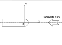
A schematic diagram of the experimental layout is shown in . The cylindrical wooden tube of 30 mm in diameter was placed orthogonal to the flow direction in the center of the test section of an open circuit wind tunnel. In order to eliminate the wake effect from the back of the cylindrical tube, a flat after-body was attached to the back half of the tube. The transparent walls of the test section had a cross-sectional area of 360 mm × 500 mm and a length of 1200 mm. Air was drawn into the test section by means of a centrifugal fan through a honeycomb bell-mouth entry. At the beginning of the experiments, the cylindrical model was aligned in the direction of the free air stream of the flow, and the velocity was set with the aid of a speed controller. The turbulence intensity of the free air stream was found to be less than 2%.
Experimental Conditions
The experimental conditions undertaken are summarized in . The solid particles used for the experimental study are solid glass spheres, namely Spheriglass A-2530 supplied by Potters Industries Inc. with average diameter sizes of 35 μm and 66 μm. The Sauter mean diameter (SMD) of the particles that is of average diameter size 66 μm has a Gaussian distribution of 10% finer than 30 μm, 50% finer than 64 μm, and 90% finer than 103 μm measured by the Malvern particle size analyzer. The specific gravity of the particles is 2.5, and the refractive index is 1.51. A fluidized bed feeder was specially designed for this experiment to inject the solid particles into the system in a controllable manner. The internal pressure of the fluidized vessel was monitored and maintained at 240 kPa. The particles were forced through an injecting nozzle upstream of the wind tunnel. The maximum bulk solids/gas mass loading ratio, defined as the mass flow rate of particles divided by the mass flow rate of air, was set less than 0.1 kg/kg. This ratio indicated that the spherical glass particles are treated as dispersed or dilute particulate phase. A filter system was incorporated in the tunnel exhaust to facilitate the removal of the particles. As shown in the Cartesian coordinate system in , the measurements were taken with an increment of 3 mm in both the y axis and the x axis. For the majority of measurements, the fiber optic probe was traversed parallel to the tube through a three-dimensional traversing mechanism. In order to obtain measurements near the tube wall region and also to avoid blocking off the laser beams by the tube, the probe was placed in an inclined position (2.72°). This enabled the measurements to be carried out right up to 1.5 mm from the tube surface.
TABLE 1 Experimental conditions
LDA Apparatus
The nonintrusive LDA has proved to be an accurate method for the measurement of instantaneous velocity components of particles suspended in fluids. In this study, the Aerometric two-component Phase Doppler Anemometry/Laser Doppler Anemometry (PDA/LDA) fiber optic system was used. The system consisted of a two-color, four-beam optical arrangement utilizing the green (wave length = 514.5 nm) and blue (wave length = 488 nm) lines of a 5 W argon–ion laser. The fiber optic probe had a lens of 400 mm focal length and a 38 mm beam separation, which produced an ellipsoid-shaped measurement volume with a diameter of 0.194 mm and a length of 4.09 mm.
All measurements were taken with the Bragg cell in the beam path to introduce a 40 MHz shift to one of the beams. This produced a shift in the Doppler frequency of 40 MHz, which eliminated the directional ambiguity that would have been present in a reversing flow with no frequency shifting. The burst spectrum analyser (BSA) used in this study (Dantec 58N10) was capable of handling data rates in excess of 170,000 velocity measurements per second, which was rapid enough to deal with all the flow conditions in this study. The data-processing method employed in this study for the determination of the desired flow parameters was called the residence time method. The data, corrected for velocity bias, were randomly collected over a set period of time. This recording time was set for 100 s based on a sample size of 5000.
Experimental Uncertainty
For LDA measurements in particle-laden flow, the main sources of error are considered to be the hardware errors, velocity bias, and fringe bias. This is particularly the case for the near-wall region with infrequent particle arrival. Long measuring times and large sampling sizes are needed to reduce the uncertainty of the ensemble statistics. In the current study, initial test measurements were performed to assess the quality of the laser Doppler signals in the near-wall region. During the experiments, silicon carbide particles of diameter 1.5 μm were added into the experimental glass spheres to determine the minimum sampling size and time. Consequently, during the real experimental measurements the repeatability was ensured to be less than 2% for the mean velocities and less than 4% for the fluctuating components.
The crossing angle of the beam can cause some uncertainty in the measurement of the velocity. The 38 mm beam spacing was estimated to have an error of ±0.5 mm, which is approximately 1%. Errors caused by the optical configuration are constant and affect all measurements equally. The BSA used eliminated any errors caused by the scattering of multiple particles. The minimum sample size of 5000 was chosen to reduce any errors caused by the ensemble statistics. The velocity bias in the LDA measurements was corrected by applying residence time weightings to the mean and fluctuating components of the velocity. The uncertainty for the mean velocity was calculated using the Student-t distribution as proposed by CitationBendat and Piersol (1971) and CitationSakakibara et al. (1995). The uncertainty is given by
Data Analysis of Incident and Rebound Particles
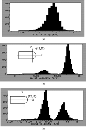
The information regarding the incident and rebound behavior of the particles was collected using Aerometric's real time analyzer (RSA) software. shows some typical examples of the axial velocity versus histogram count at various positions around the tube model. At a free-stream velocity where incoming particles were far away from the tube, a normal distributed histogram peak yields an average horizontal velocity around 13.6 m/s (see ). They can be classified as incident particles. At the position of x = 12 mm and y = 27 mm, two histogram peaks shown in indicated that, other than mainstream particles travelling at an average horizontal velocity of around 13.6 m/s, a small proportion of particles was seen moving at a lower velocity (∼7 m/s). The latter could be classified as rebound particles because they have been accelerated by the mainstream fluid flow after rebounding from the tube surface, subsequently reaching the measuring point. With the aid of this RSA LDA software, each peak from the histogram graph could be separated into different categories; all velocity information as well as the particle counts for each peak can be obtained. A significant proportion of about 19% of the particles was congregated in the rebounding stream, with a horizontal velocity of around 7 m/s, as can be seen in . At the measuring point of x = 12 mm and y = 12 mm, at a 45° angle and about 3 mm away from the surface of the tube, a larger proportion of 59% of the particles was recorded in the rebounding stream. Here, a higher horizontal velocity of 9.4 m/s was measured when compared to the previous position in .
RESULTS AND DISCUSSION
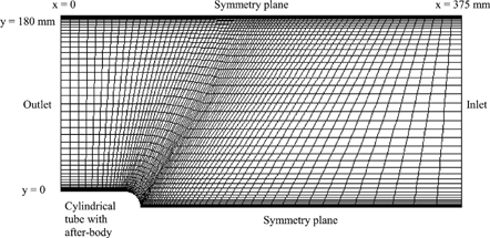
Numerical simulations are performed on the computational domain and grid distribution of a total of 3750 quadrilateral elements as illustrated in . The measured data from experiments at the location x = 375 mm is taken as the inlet boundary conditions for the present computation. The flow is assumed to be fully developed at the outer boundary, on which zero normal gradients of the variables are imposed, and to be symmetrical at the top and bottom of the computational domain. Grid refinement was performed near the solid boundary and the top and bottom boundaries of the computational domain. Additional computational runs were performed on the coarser and finer grids of 1875 and 7500 quadrilateral elements to check for grid independence. A comparison of results showed that the maximum changes of 1.9% in the axial mean gas-velocity profiles between the grid distribution of 3750 and 7500 quadrilateral elements were smaller than the 10.5% found between the grid distribution of 1875 and 3750 quadrilateral elements. Consequently, the accuracy of the numerical solutions obtained on the grid distribution of 3750 quadrilateral elements is deemed satisfactory.
The flow conditions used here in the computation for comparison with the experiment are as follows:
| 1. | bulk flow velocity, U b = 11 m/s; | ||||
| 2. | tube diameter, D = 0.03 m; | ||||
| 3. | Reynolds number, Re = U b D/ν g = 22,000; | ||||
| 4. | particle diameter size, d p = 66 μm | ||||
| 5. | particle material density, ρ s = 2,990 kg/m3 (spherical glass); | ||||
| 6. | Stokes number, St = 17.68; and | ||||
| 7. | mean normal and tangential restitution coefficients, e n = 0.3 and e t = 0.9. | ||||
In the following section, we present the comparison between the numerical and experimental results on particle flow behavior over a cylindrical body. The particle flow behavior near the solid surface was investigated in more detail with a parametric computational study subjected to varying Stokes and Reynolds numbers. The experimental velocities of incident and rebound particles obtained separately from experiments were also compared with the Lagragian predictions. Finally, the effect of varying restitution coefficients on the particle flow pattern was investigated and discussed.
Comparison Between Computational and Experimental Results
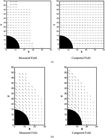
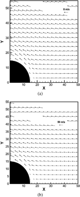
illustrates the comparison between the computational and experimental velocity vector plots at Re = 22,000 and St = 17.86. It can be observed from that all incident particles injected from the upstream station were unperturbed by the gas flow before impinging on the tube surface. This is because of the incident particles having such a high inertia (high Stokes number), which were hardly affected by the flow turbulence. reveals the characteristics of the rebounded particles subsequently impacting on the tube surface. The largest directional change of the movement of the particles were the particles found travelling back to the mainstream flow when they impinged near the stagnation point of the cylindrical tube. Particles impinging away from the stagnation point of the cylindrical tube resulted in their being reflected off towards the downstream gas flow, as shown in . The predicted incident and rebound behavior of the particles agreed very well with the measurements. These encouraging computational results provide confidence in the usage of the Lagragian approach to study the complex particle flow behavior near wall surfaces.
FIG. 4 Comparison of particle velocity field between experiment and computation at Re = 22,000 and St = 17.86: (a) incident particles and (b) rebound particles.
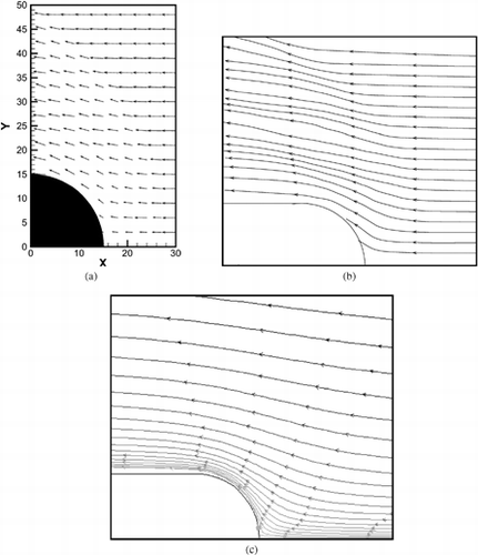
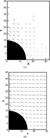
represents the computed flow pattern of mean particle flow vectors over the tube and the streamlines of the particle and gas flow. The mean particle flow pattern in clearly indicates the sudden change of the flow pattern over the cylindrical wall surface due to the presence of rebound particles, showing the difference from the mean gas-flow pattern. This is confirmed by the difference of streamlines plotted in of mean particle flow and of gas flow alone.
Particle Flow Behavior Near the Wall Surface
Additional experiments were performed with the combination of two different particle sizes (35 μm and 66 μm) and three flow velocity conditions (8 m/s, 11 m/s, and 13.7 m/s) in order to gain a better understanding of the particle flow behavior near the cylindrical wall surface. The corresponding combinations of the experimental conditions are listed in . As observed from experiments, the particle flow was not greatly influenced by the gas flow because of the relatively high Stokes number.
illustrates the measured flow patterns of rebound particles and mean particle flow for Re = 16,000 and St = 12.86. With this Stokes number being lower than the above of St = 17.86, the extent of the particles rebounding back to the upstream gas flow was reduced. Nevertheless, the mean particle flow patterns near the wall surface for St = 12.86 was comparatively similar to St = 17.86.
FIG. 6 Measured flow pattern at Re = 16,000 and St = 12.86: (a) rebound particles and (b) mean particle flow.
The measured mean particle-flow velocity profiles for two particle sizes of 35 μm and 66 μm in the vicinity of the cylindrical surface is represented in . The mainstream gas-flow velocity was set at 11 m/s. Experimental results clearly showed that the particle size has an effect on the velocity distribution before impact, at the stagnation point, and over the solid body at downstream. The lighter particles seemed to possess less inertia and be governed more by the drag of the fluid when compared to the heavier particles. depicts the influence of varying gas-flow velocities on the measured mean particle flow of a particle size of 35 μm. The mean particle velocity profiles at Re = 220,000 and 270,000 being similar strongly suggests that the particle inertia was greatly suppressed by the high drag forces. From these results it can also be inferred that the high Reynolds number gas flow due to the rapid mainstream gas velocities would significantly reduce the rebound tendency of the particles. This was subsequently verified through computations where numerical simulations were carried out for the cases of Re = 16,000 and 100,000 in .
FIG. 7 Measured mean particle-flow velocity profiles in the vicinity of the tube surface for an axial velocity of 11 m/s with particle sizes of 35 μm and 66 μm over a single tube.
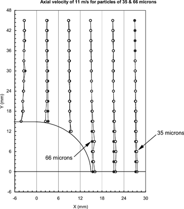
FIG. 8 Measured mean particle-flow velocity profiles for three flow velocities over a single tube with particle size of 35 μm.
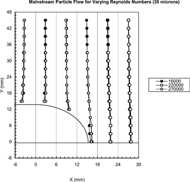
FIG. 9 Computed flow patterns of rebound particles at St = 1.0: (a) Re = 16,000 and (b) Re = 100,000.

FIG. 10 Computed flow patterns of mean particle flow at St = 1.0: (a) Re = 16,000 and (b) Re = 100,000.
For particles with relatively small Stokes number, the particle motion is influenced by the gas flow, which affects the particle rebounding and the mean particle-flow pattern characteristics near the wall surface. In order to confirm this observation, this can be parametrically studied through higher Reynolds numbers, therefore imposing high inlet velocity into the wind tunnel facility. Owing to the structural integrity of the wind tunnel facility, only moderately high wind velocities were sustainable. To overcome this limitation, a numerical simulation using the CFD and Lagragian model was utilized. demonstrate the computed flow patterns of mean particle flow and of rebound particles for Re = 16,000 and 100,000 at a fixed low St = 1.0. The results candidly revealed that the particle rebounding zone was significantly reduced with the increasing fluid Reynolds number attributed by the fluid flow suppressing the rebound tendency of the particles.
Particle Rebound Zone
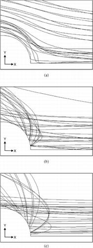
represents a series of particle trajectories using the Lagrangian approach over the cylindrical body for a fixed Re = 16,000 and three different Stokes numbers of 0.1, 4.97, and 17.6. For a small Stokes number, the particles did not collide with the wall (see ). This was due to the low inertia, and because the particles were strongly influenced by the fluid fluctuations they followed the mean fluid flow. For an intermediate Stokes number, particles impinged on the wall and were rebounded to some considerable distance away from the wall. For particles with a larger Stokes number, the distance travelled by the rebound particles significantly increased (see ). This was attributed to the rebound particles possessing higher inertia and gaining more momentum to overcome the drag of the fluid.
FIG. 11 Particle trajectories at different Stokes numbers: (a) St = 0.1, (b) St = 4.97, and (c) St = 17.6.
It is possible to use the Lagrangian simulation above to determine the particle rebound distance, X prd, along the stagnation line, x axis, and Y prd along the y axis to locate the particle rebound zone or particle rebound layer, in which the mean particle flow field was significantly modified by the rebound particles. This distance is dependent on the particle inertia (Stokes number), flow velocity (fluid Reynolds number), and particle–wall impact characteristics (restitution coefficients). reveals the normalized particle rebound distance (X prd divided by the tube diameter) as a function of particle Stokes numbers, with a fixed Reynolds number and fixed mean normal and tangential restitution coefficients. Good agreement was achieved between the experimental and computational results. The results indicated that particle rebound distance increased with higher particle Stokes number. demonstrates, however, that the normalized particle rebound distance decreased with higher fluid Reynolds number. As observed in , the fluid flow greatly suppressed the rebound tendency of the particles. The relationship between the normalized rebound distance with the normal and tangential restitution coefficients is shown in . illustrates the curve of the normalized rebound distance versus normal restitution coefficient with a fixed e t = 0.6, while provides the curve of the normalized rebound distance versus tangential restitution coefficient with a fixed e n = 0.3. The results indicated that the normal restitution coefficient exerted greater influence on the rebound particle flow field than the tangential restitution coefficient.
FIG. 12 Normalized particle rebound distance along the x direction as a function of Stokes number with a fixed Reynolds number (Re =16,000) and fixed restitution numbers (e n = 0.3, e t = 0.9).
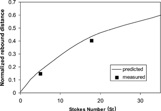
FIG. 13 Particle rebound distance as a function of Reynolds number with a fixed Stokes number (St = 17.86) and fixed restitution numbers (e n = 0.3, e t = 0.9).
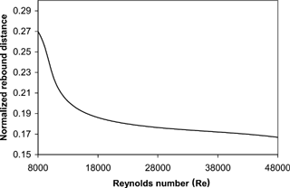
FIG. 14 Particle rebound distance as a function (a) of normal restitution coefficient with fixed e t = 0.6 and (b) of tangential restitution coefficient with fixed e n = 0.3 at Re = 22,000 and St = 17.86.
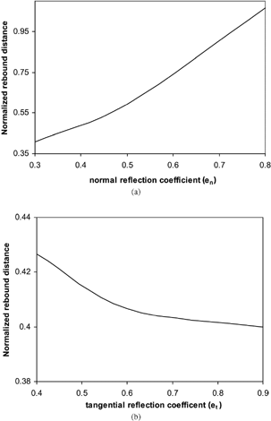
The sensitivity study performed in corresponded very closely to the experiments by CitationLi et al. (1997), where they also observed no significant differences in restitution between the purely normal collisions and the tangential (oblique) ones over the range of about 5° to 90°. This implied that the majority of the generated strain energy was restored as kinetic energy and favored the normal rebound process. In CitationLi et al. (1997) experiments, the high normal restitution coefficient established in their impact study confirmed the initial trials performed in our experiments while employing solid metal material of similar particle sizes. The experimental uncertainty of CitationLi et al.'s (1997) values of the coefficient of restitution has been estimated to be less than 10%, with 95% confidence.
Although the tangential motion may not couple with or significantly influence the impact of the particle rebounding behavior, the question of differences with respect to capture and deposition requires more investigation, especially for small initial impact velocity. As the initial velocity of particle grows smaller, the significance of adhesion forces increases, eventually reaching a point of where no rebound occurs and the particle is captured. Furthermore, for an oblique collision with e n = 0, a particle can retain significant kinetic energy associated with tangential and rotational motion, and the particle will migrate on the surface. It is noted that particle rotation was not considered in this study.
The restitution model in commercial code FLUENT could be improved through better modelling the particle impact characteristics based on the phenomenological model formulated by CitationBrach and Dunn (1998). The rigid body impact model can be incorporated within the code by evaluating the rebounding velocities and particle rotation Ω as
CONCLUSIONS
The physical behavior of particle rebounding flow in the immediate vicinity of a solid wall was experimentally studied via a two-dimensional LDA technique and numerically predicted via a CFD and Lagrangian trajectory model. A substantial amount of work undertaken in this article was to elucidate further the understanding of the complex particle flow near wall surfaces and the ability to evaluate the incident and rebound particles characteristics during the particle–wall surface interaction. Good agreement was achieved between the computational and experimental results. Both computational and experimental results revealed that the particle rebounding flow pattern in the vicinity of the wall was mainly affected by particle inertia (Stokes number). The gas flow at high Reynolds number was found to suppress the rebound tendency of the particles, and further parametric investigation demonstrated that only the normal restitution coefficient exerted greater influence on the rebound particle flow field rather than the tangential restitution coefficient. The beneficial contributions gained by employing both experimental and computational methods to investigate particle motion in wall-dominated gas–particle flow on a cylindrical body surface create enormous opportunities to investigate further the erosion patterns and heat transfer performance in tube bundle structure commonly found in heat exchangers. In such a structure, the particles rebounding off the initial cylindrical tube upstream greatly influenced the erosion distribution of subsequent cylindrical tubes downstream. This is significantly evident on a staggered arrangement of tube banks confined in the flow space of the heat exchangers. Understanding the erosion behavior is important in these industrial devices, as it affects the operational thermodynamic efficiency. Work is in progress to predict the erosion distribution in this complex geometry, and the investigations will further quantify the particle rebounding behavior in the immediate vicinity on these curved wall surfaces. The work will also be beneficial in the study of aerosol particle bounce and re-entrainment characteristics in inertial impactors.
NOMENCLATURE
| a,b | = |
exponential constants in EquationEquation (6) |
| d p | = |
particle diameter |
| D | = |
diameter of tube |
| e n , e t | = |
mean normal and tangential restitution coefficients |
| k | = |
constant in EquationEquation (16) |
| l | = |
constant in EquationEquation (16) |
| N | = |
sample size |
| r | = |
particle radius |
| Re | = |
Reynolds number |
| s | = |
sample standard deviation |
| St | = |
Stokes number = (ρ s d p 2 U b )/(18μ g D) |
| t | = |
area under the Student-t distribution |
| x | = |
horizontal location along x axis |
|
| = |
simple mean |
| X prd | = |
particle rebound distance along the horizontal stagnation line |
| y | = |
vertical location along y axis |
| Y prd | = |
particle rebound distance along the vertical direction |
| u c | = |
capture velocity or critical velocity |
| u i , u j | = |
velocity |
| ū i | = |
mean velocity |
| u i ′ | = |
fluctuating velocity components |
|
| = |
local rms velocity fluctuations |
| u p i , u p r | = |
incident and rebound particle velocity |
| U b | = |
bulk velocity |
Greek Letters
| ϵ | = |
dissipation rate of turbulent kinetic energy |
| κ | = |
turbulent kinetic energy |
| μ | = |
ratio of the tangential to normal impulse |
| ν g | = |
kinematic gas viscosity |
| ρ | = |
adhesion coefficient |
| ρ s | = |
material density of particulate phase |
| Ω | = |
incident particle rotation |
| ζ | = |
normally distributed random number |
| Ω | = |
rebounding particle rotation |
Subscripts
| n | = |
normal direction |
| t | = |
tangential direction |
| ij | = |
1, 2 (x, y) |
Superscript
| g | = |
gas phase |
REFERENCES
- Bendat , J. S. and Piersol , A. G. 1971 . Random Data: Analysis and Measurement Procedures , New York : Wiley-Interscience .
- Brach , R. M. and Dunn , P. F. 1998 . Models of Rebound and Capture for Oblique Microparticle Impacts . Aerosol Sci. Technol. , 29 : 379 – 388 .
- Dunn , P. F. , Brach , R. M. and Caylor , M. J. 1995 . Experiments on the Low-Velocity Impact of Microspheres with Planar Surfaces . Aerosol Sci. Technol. , 23 : 80 – 95 .
- Fan , J. , Zhang , X. , Cheng , L. and Cen , K. 1997 . Numerical Simulation and Experimental Study of Two-Phase Flow in a Vertical Pipe . Aerosol Sci. Technol. , 27 : 281 – 292 .
- Fan , J. , Zhou , D. , Jin , D. and Chen , K. 1991 . Numerical Simulation of Tube Erosion by Particle Impaction . Wear , 142 : 171 – 184 .
- Grinshpun , S. A. , Willeke , K. and Ulevicius , V. 1997 . Effect of Impaction, Bounce and Reaerosolization on the Collection Efficiency of Impingers . Aerosol Sci. Techol. , 26 : 326 – 342 .
- Jun , Y.-D. and Tabakoff , W. 1994 . Numerical Simulation of a Dilute Particulate Flow in Tube Banks . ASME J. Fluids Eng. , 116 : 770 – 777 .
- Li , X. , Dunn , P. F. and Brach , R. M. 1997 . “ Experiments on the Oblique Impact of Microspheres with Planar Surfaces with Known Patterns ” . In 16th Annual Meeting, American Association of Aerosol Research p. 481 Denver, CO, , USA 13–17 October
- Morsi , S. A. and Alexander , A. J. 1972 . An Investigation of Particle Trajectories in Two-Phase Systems . J. Fluid Mech. , 55 : 193 – 208 .
- Morsi , Y. S. , Yang , W. and Atapattu , D. D. 1996 . “ Experimental Investigation of Flow Filed in a Tube Bank in Cross Flow ” . In Proceedings of the First Australiasian Conference on Laser Diagnostics in Fluid Mechanics and Combustion pp. 173 – 179 . Sydney, , Australia
- Orszag , S. A. , Yakhot , V. and Flannery , W. S. 1993 . “ Renormalization Group Modelling and Turbulence Simulations ” . In Near Wall Turbulence Flows , Edited by: So , R. M. C. , Speziale , C. G. and Launder , B. E. pp. 1031 – 1046 . Amsterdam : Elsevier . edited by
- Saad , Y. and Schultz , M. H. 1986 . GRMES: A Generalized Minimal Residual Algorithm for Solving Nonsymmetric Linear Systems . SIAM J. Sci. Stat. Comput. , 7 : 856 – 869 .
- Sakakibara , J. , Wicker , R. B. and Eaton , J. K. 1995 . “ Measurements of the Particle-Fluid Velocity Correlation and the Extra Dissipation in a Round Jet ” . In Technical Report IL-128 , Stanford, CA : Thermosciences Division of Mechanical Engineering Department, Stanford University .
- Schade , K.-P. , Erdmann , H.-J. and Petrak , D. Experimental Investigation of the Particle-Wall Collision under Particular . Consideration of the Wall Roughness Fluids Engineering Division Conference . pp. 759 – 766 . ASME FED-236
- Schade , K.-P. and Hadrich , Th. Investigation of Influence of Wall Roughness on Particle-Wall Collision Proceedings of ICMF'98 . 3rd International Conference on Multiphase Flow . June 8–12 , Lyon, France.
- Sommerfeld , M. 1992 . Modelling of Particle-Wall Collisions in Confined Gas-Particle Flows . Int. J. Multiphase Flow , 18 : 905 – 926 .
- Sommerfeld , M. and Huber , N. 1995 . “ A Laser Strobe Technique Combined with Digital Image Analysis to Study Particle-Wall Collisions, Modern Measuring Techniques for Multiphase Flows ” . In Proceedings International Symposium on Measurement Techniques for Multiphase Flows pp. 428 – 440 . Nanjing, , China
- Sommerfeld , M. and Huber , N. 1999 . Experimental Analysis and Modelling of Particle-Wall Collisions . Int. J. Multiphase Flow , 25 : 1457 – 1489 .
- Tabakoff , W. , Malak , M. F. and Hamed , A. 1987 . Laser Measurements of Solid Particle Rebound Parameters Impacting on 2024 Aluminium and 6A1–4V Titanium alloys . AIAA J. , 25 : 721 – 726 .
- Tsai , C. J. and Cheng , Y. H. 1995 . Solid Particle Collection Characteristics on Impaction Surfaces of Different Designs . Aerosol Sci. Techol. , 23 : 96 – 106 .
- Tu , J. Y. and Fletcher , C. A. J. 1995a . “ Continuum Hypothesis in the Computation of Two-Phase Flows ” . In Computational Fluid Dynamics , Edited by: Leutloff , D. and Srivastava , R. C. pp. 1 – 10 . Heidelberg : Springer-Verlag . edited by
- Tu , J. Y. and Fletcher , C. A. J. 1995b . Numerical Computation of Turbulent Gas-Solid Particle Flow in a 90° Bend . AIChE J. , 41 : 2187 – 2197 .
- Tu , J. Y. , Fletcher , C. A. J. , Morsi , Y. S. , Yang , W. and Behnia , M. 1998 . Numerical and Experimental Studies of Turbulent Particle-Laden Gas Flow in an In-Line Tube Bank . Chem. Eng. Sci. , 53 : 225 – 238 .
- Tu , J. Y. 2000 . Numerical Investigation of Particulate Flow Behavior in Particle-Wall Impaction . Aerosol Sci. Techol. , 32 : 509 – 526 .
- Tu , J. Y. , Fletcher , C. A. J. , Zhou , Y. and Morsi , Y. S. 2001 . Computational Analysis of Turbulent Gas-Particle Flow in Tube Banks Using a Two-Way Coupling Model . Chem. Eng. Comm. , 188 : 207 – 229 .
- Van Doormal , J. P. and Raithby , G. D. 1984 . Enhancements for the SIMPLE Method for Predicting Incompressible Fluid Flow . Num. Heat Transfer , 7 : 147 – 163 .
- Yakhot , V. and Orszag , S. A. 1986 . Renormalization Group Analysis of Turbulence 1, Basic Theory . SIAM Journal on Scientific Computing , 1 : 3 – 51 .
