Laser Doppler Velocimetry (LDV) was used to measure the turbulence structure of the flow field in a cyclone separator. The measurement results showed that a stick inserted in the cyclone changed the distribution of the flow field. A flow wake region downstream the stick decreased the tangential velocity and increased the turbulence intensity. The size and shape of the stick cross-section had a remarkable effect on the distribution of the flow wake and the turbulence structure of the flow field. The changes of the flow field explained how the stick reduced the pressure drop over the cyclone.
INTRODUCTION
The cyclone separator is widely used in industry to separate solid from gas. Because the particle is removed by the centrifugal force in the cyclone, the smaller the particle to be removed, the higher the energy loss of the cyclone. In the very early period of cyclone separator use, researchers noticed that a great part of the energy consumption of the cyclone had not been used to separate the particle effectively. Thus, many structures had been applied into the cyclone to reduce the energy loss (CitationShepherd and Lapple 1939; CitationBrowne and Strauss 1978; CitationZhou and Soo 1990; CitationO'Doherty et al. 1992; CitationGriffiths et al. 1996). CitationWang and Ye (1999) reported that a thin stick in the cyclone could reduce the pressure drop across a cyclone by approximately 20% without affecting the total separation efficiency at the same flow rate. They probed the effect of a stick on the flow field in the cyclone using five-orifice Pitot tube and concluded that the pressure drop reduction was due to the wake vortex downstream of the stick (CitationWang et al. 2001). This finding led to the hypothesis that adding vortices could reduce the pressure drop in the turbulent flow. Limited by the measurement method, their hypothesis has not been verified. Laser-Doppler velocimetry (LDV) can be used to measure both the mean velocity and some turbulence parameters, such as root mean square velocity and turbulence intensity. In recent years, a number of authors reported measurements using LDV in cyclone separators (CitationZhou and Soo 1990; CitationHoekstra et al. 1999; CitationSolero and Coghe 2002; CitationPeng et al. 2002). Most of theses focused on the mean flow field and presented very little information about the turbulence in the swirling flow of the cyclone. The present research was conducted to study changes in the turbulence within the cyclone that resulted from the stick and the accompanying pressure drop reduction.
EXPERIMENTAL EQUIPMENT
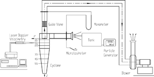
The experimental set-up is shown in . It consists of a cyclone model, a LDV system and a feeding system. The Stairmand-type cyclone, which was made of Plexiglas, is illustrated in . The geometrical swirl number S of this cyclone was equal to 3.11, based on the definition: ' where Ai was the area of the tangential inlet, Dr was the diameter of the exit tube, and D was the diameter of the cyclone. A number of slots on the side of the cyclone were fitted with optical glass.
Air flow was supplied by the blower through a slide valve, and the flow rate was measured by a microtasimeter. LDV measurements were carried out at an inlet Reynolds number of Re = 6.1 × 10⁴, both with and without a stick inserted.
A manometer was used to measure the total pressure drop across the cyclone. The flow field in the cyclone was measured by two-component Laser-Doppler Velocimetry (LDV). The LDV was operated in backscatter mode, and signal processing was performed with a Doppler burst correlator (TSI Model IFA755). The laser beams were focused using a 350 mm lens. The measurements were performed at six cross-sections along four different radial directions (20°, 100°, 200°, and 280°) in the cyclone. For each section, about 30 locations along the radius were probed. The mean and turbulent flow parameters at each location were calculated from 1000 data points per channel.
A feeding system was designed to provide the main flow line with glycol droplets about 2 μm in diameter. The ability of droplets to follow the centrifugal gas flow streamlines is characterized in terms of Stokes number, which was defined as the ratio of the aerodynamic relaxation time of the particle τ p = ρpdp
2/18μ (where ρp and dp represent particle density and diameter, and μ the gas viscosity), and the characteristic flow time (where R represents the radius of cyclone separator and Vtmax the maximum of the tangential velocity) of the vortex field. The Stokes number for 2 μm droplets in the cyclone results about 5.4 × 10− 4. The small value indicates that the droplets should be added to follow the gas field without slip, so they may be considered as gas tracer.
Sticks with different sizes and shapes of cross-section are inserted in the cyclone. One end of the stick is fixed at the point (radius of 54 mm and direction of 175°) on the top cover of the cyclone separator, and the other is fixed at the cone bottom in the same azimuth. The performance of the pressure drop reduction for each stick is listed in .
TABLE 1 Type of stick and pressure drop reductionFootnote 1 , Footnote 2
EXPERIMENTAL RESULTS
The Effect of Stick on the Mean Flow Field
The mean tangential and axial velocities in the cyclone without a stick are similar to those reported by CitationZhou (1990) CitationHoekstra et al. (1999), CitationSolero (2002), and CitationPeng et al. (2002). Insertion of a stick into the cyclone decreased the mean tangential velocity remarkably. The maximum in the tangential velocity disappeared. The resulting tangential velocity curve was flat, as shown in . In the wake region immediately downstream of the stick (in the direction of 200°), the tangential velocity decreased sharply giving the velocity curve a “V” shape. The distribution of tangential velocity in four directions on the two different cross-sections is shown in . The velocity in the wake region increased gradually along the flow rotation direction downstream of the stick, so that the velocity profile was nearly flat after one complete rotation. In the direction of 100° (upstream of the stick), the flow wake region disappeared completely, but the velocity was smaller than that of the original one in the cyclone without a stick, as shown in and . These changes of the tangential velocity above showed that the stick not only changed the original Rankine vortex structure in the cyclone, but also turned the flow field distribution to be more non-axisymmetrical. Furthermore, the stick had a stronger effect on the tangential velocity in the cylindrical section of the cyclone than in the conical section.
FIG. 3 Effect of stick on the mean flow field (A: with stick; B: without stick). (a) Tangential velocity in different cross section; (b) Tangential velocity in different direction; (c) Axial velocity in different cross section.
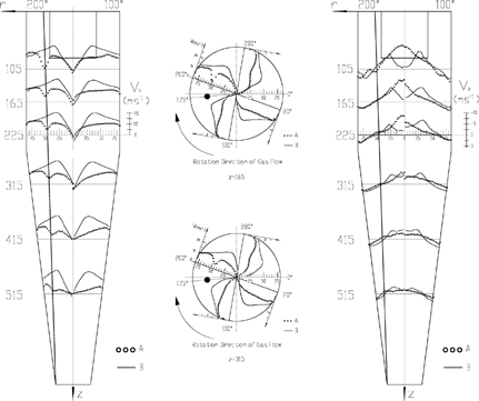
Compared with the tangential velocity, the axial velocity showed a small change in the . It increased only in the center region of the cylindrical section of the cyclone with a stick, which was helpful to reduce the flow drag in the cyclone.
The Effect of a Stick on the Root-Mean Square (RMS) Velocity
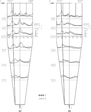
The tangential and axial components of the RMS velocity were high both near the wall and in center region of the cyclone without a stick, as shown in . The values of these two components of RMS were not equal, so the turbulent flow was neither homogenous nor isotropic. When the stick was inserted into the cyclone, the tangential RMS (RMSt) increased to a peak value in the flow wake region, as did the axial RMS (RMSz) near the boundary of the stick. These two RMS components remained nearly unchanged in the other regions of the cyclone. Thus, the stick had a very limited effect on the RMS velocity.
The Effect of a Stick on the Turbulence Intensity
The turbulence intensity in the LDV measurement is defined as:
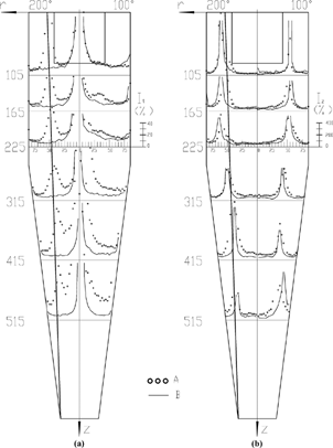
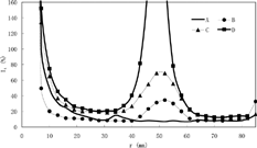
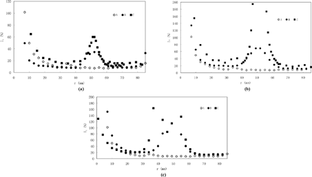
where is the mean velocity. Thus, the turbulence intensity is very high where the mean velocity is very small, leading to the sharp peak in . The extremely high values are not shown due to the limitations of the figure size. The tangential component of turbulence intensity It was enhanced by the presence of a stick in the cyclone, especially in the flow wake region. However, the axial turbulence intensity Iz only changed slightly. The stick had very little effect on Iz since it was inserted axially in the cyclone.
The Mechanism of the Stick Reducing the Pressure Drop in the Cyclone
The total energy loss in the cyclone includes the rotational kinetic energy loss, turbulence energy loss, and other types of energy loss. The other types of energy loss do not vary under fixed inlet Reynolds number of the cyclone with and without a stick inserted. LDV measurement results presented above suggest that the stick reduce the rotational kinetic energy and increase the turbulent energy in the cyclone. The rotational kinetic energy per unit mass flow can be calculated from the tangential velocity data, which was given by:
The effect of the stick on Ek is showed in . Comparing the reduction in Ek with the corresponding pressure drop reduction (in ) reveals that the rotational kinetic energy was reduced more than was the total pressure drop through the cyclone separator. The turbulent kinetic energy is related to the RMS velocity, but two-component LDV measurements do not provide sufficient information to determine this quantity. However, based on the above comparison, the increase in the turbulence energy appears to be smaller than the reduction in rotational kinetic energy. This reduction in the total energy loss leads to a net reduction in the pressure drop through the cyclone. This explains the previous experimental results of CitationWang and Ye (1999) that a stick in the cyclone could reduce the pressure drop by approximately 20% at a given flow rate without affecting the total separation efficiency.
TABLE 2 The rotational kinetic energy reduction caused by the stick
The Effect of the Stick Structure on the Flow Field
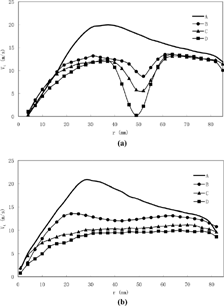
The length of the stick was fixed due to its method of installation. Thus, this paper only studies how the size and shape of the stick cross-section affect on the flow field. showed that the pressure drop reduction in the cyclone varied with the size and shape of the stick. A cylindrical stick reduced the pressure drop from 32.2% to 43.6% as the width of the cross-section increased from 5 mm to 15 mm. A rectangular-shaped stick reduced the pressure drop more than a cylindrical one with the same cross-section width. These results could be explained by the changes of the flow field measured by LDV as described in the following section.
For a given cross-section shape, increasing cross-section size resulted in a wider flow wake region, and a sharper decrease in the tangential velocity, as shown in . Upstream of the stick, the tangential velocity also decreased significantly as the width of the stick cross-section was increased from 5 mm to 15 mm, as shown in .
FIG. 6 Effect of b on the tangential velocity: (a) downstream the stick (200°); (b) upstream the stick (100°). (A: without stick; B: with stick, b = 5; C: with stick, b = 10; D: with stick. b = 15).
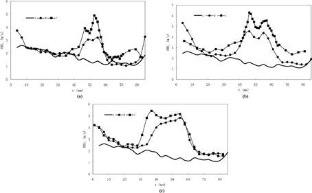
shows the influence of stick size on RMSt while shows that on It. These results suggest that increasing the size of stick cross-section enhanced the fluctuation in the flow wake region.
FIG. 7 Effect of b on the tangential RMS velocity downstream the stick (A: without stick; B: with stick, b = 5; C: with stick, b = 10; D: with stick, b = 15).
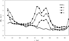
FIG. 8 Effect of b on the turbulence intensity downstream the stick (A: without stick; B: with stick, b = 5; C: with stick, b = 10; D: with stick, b = 15.
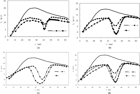
The rectangular-shaped stick both reduced the tangential velocity and increased the width of flow wake more than did a cylindrical stick with the same cross-section size, as shown in . Moreover, the rectangular-shaped stick with size of b = 10 mm reduced the tangential velocity more than did the cylindrical one with size of b = 15 mm, as shown in . This indicates that the effect of stick shape on the flow field was stronger than that of its size.
FIG. 9 Effect of cross-section shape on the tangential velocity downstream the stick (a) b = 5 (A: without stick; B: with stick, cylindrical; C: with stick, rectangular-shaped); (b) b = 10 (A: without stick; B: with stick, cylindrical; C: with stick, rectangular-shaped); (c) b = 15 (A: without stick; B: with stick, cylindrical; C: with stick, rectangular-shaped); (d) (A: without stick; B: with stick, b = 10, cylindrical; C: with stick, b = 10, rectangular-shaped; D: with stick, b = 15, cylindrical).
The sharp edge of the rectangular stick produces sudden separation of the flow, and enhances the fluctuations in the flow wake, leading to a greater increase in RMSt and It than did the cylindrical one, as shown in the and .
FIG. 10 Effect of cross-section shape on the tangential RMS velocity downstream the stick (a) b = 5 (A: without stick; B: with stick, cylindrical; C: with stick, rectangular-shaped); (b) b = 10 (A: without stick; B: with stick, cylindrical; C: with stick, rectangular-shaped); (c) b = 15 (A: without stick; B: with stick, cylindrical; C: with stick, rectangular-shaped).
Effect of cross-section shape on the turbulence intensity downstream the stick (a) b = 5 (A: without stick; B: with stick, cylindrical; C: with stick,rectangular-shaped); (b) b = 10 (A: without stick; B: with stick, cylindrical; C: with stick, rectangular-shaped); (c) b = 15 (A: without stick; B: with stick, cylindrical; C: with stick, rectangular-shaped).
CONCLUSION
Insertion of a stick into the cyclone separator forms a flow wake region that decreases the tangential velocity, and increases the RMS velocity and turbulence intensity. The changes in the flow field leads to pressure drop reduction of the cyclone separator, which means that the decreasing part of the rotational kinetic energy is greater than the increasing part of the turbulence energy. The cross-sectional shape and size of the stick both affect the flow field and, therefore, the pressure drop reduction. A large or rectangular cross-section decreased the tangential velocity and increased the RMS velocity and turbulence intensity more than did a smaller or cylindrical one.
Acknowledgments
This work was supported by National Natural Science Foundation of China (No. 10172055).
Notes
1All of the stick with rectangular shaped cross-section has the same depth 1 mm.
2In the table above, the pressure drop reduction of the cyclone was calculated based on the drag coefficient. The pressure drop over a cyclone ΔP was often reported as an empirical function of the drag coefficient ξ, gas density ρ and the inlet velocity Vi:
REFERENCES
- Browne , J. M. and Strauss , W. 1978 . Pressure Drop Reduction in Cyclones . Atm. Envir. , 12 : 1213 – 1221 .
- Griffiths , A. J. , Yazdabadi , P. and Syred , N. 1996 . The Use of Centre Bodies and De-swirl Vanes in the Exhaust of Cyclone dust Separators . Proceedings of the Institution of Mechanical Engineers , 210 : 193 – 203 .
- Hoekstra , A. J. , Derksen , J. J. and Van Den Akker , H. E. A. 1999 . An Experimental and Numerical Study of Turbulent Swirling Flow in Gas Cyclones . Chemical Engineering Sci. , 54 : 2055 – 2065 . [CROSSREF]
- O'Doherty , T. , Biffin , M. and Syred , N. 1992 . The Use of Tangential Offtakes for Energy Savings in process industries . Proceedings of the Institution of Mechanical Engineers. , 206 : 99 – 109 .
- Peng , W. Hoffmann , A. C. 2002 . Flow Pattern in Reverse-Flow Centrifugal Separators . Powder Technol. , 127 : 212 – 222 . [CROSSREF]
- Shepherd , C. B. and Lapple , C. E. 1939 . Flow Pattern and Pressure Drop in Cyclone Dust Collectors . Ind. Eng. Chem. , 31 : 972 – 984 . [CROSSREF]
- Solero , G. and Coghe , A. 2002 . Experimental Fluid Dynamic Characterization of a Cyclone Chamber . Experimental Thermal and Fluid Sci. , 27 : 87 – 96 . [CROSSREF]
- Wang , L. Z. and Ye , L. 1999 . Reducing Pressure Drop in Cyclone by a Stick . Aerosol Sci. Technol. , 31 : 187 – 193 . [CROSSREF]
- Wang , L. Z. , Yan , Q. S. and Liu , L. L. 2001 . Effect of a Stick on the Flow Field in a Cyclone and the Pressure Drop Reduction Mechanism . Aerosol Sci. Technol. , 35 : 909 – 913 . [CROSSREF]
- Zhou , L. X. and Soo , S. L. 1990 . Gas-Solid Flow and Collection of Solids in a Cyclone Separator . Powder Technol. , 63 : 45 – 53 . [CSA] [CROSSREF]
