This article introduces a new mathematical model that predicts the pressure drop in a tangential inlet cyclone. The model calculates the pressure drop from the frictional losses in the cyclone body, using a wall friction coefficient based on the surface roughness and Reynolds number. The entrance and exit losses are also included in the model by defining new geometrical parameters. The pressure drop coefficient is obtained as a function of cyclone dimensions and operating conditions. The model is validated by studying 12 different cyclones presented in the literature. Comparison of the model results with predictions and measurements published in the literature show that the new model predicts the experimental results quite well for a wide range of operating conditions covering a flow rate of 0.3–220 l/s and a temperature range of 293–1200°K, in different cyclones. The pressure drop coefficient is also examined in view of the outlet pipe diameter, friction coefficient, surface roughness, and Reynolds number.
NOMENCLATURE
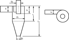
| a | = |
flow width, m |
| a d | = |
modified, dimensionless flow width, − |
| a 0 | = |
inlet width, m |
| a 3 | = |
flow width at the cone apex, m |
| b | = |
inlet height, m |
| c | = |
cylinder body height, m |
| D d | = |
dimensionless cyclone diameter |
| D hl, D h | = |
hydraulic diameter, m |
| D 1 | = |
diameter of cylindrical cyclone body, m |
| D 2 | = |
outlet pipe diameter, m |
| D 3 | = |
cone apex (or dust outlet) diameter, m |
| D 3m | = |
modified cone apex diameter, m |
| f | = |
friction coefficient, − |
| f 0 | = |
average friction coefficient, − |
| h | = |
outlet height, m |
| k | = |
surface roughness, m |
| K | = |
Pressure drop coefficient, − |
| l | = |
streamwise distance from inlet, m |
| l n | = |
normalized streamwise distance from inlet, m |
| L v | = |
vortex length, m |
| L 0 | = |
cyclone height, m |
| p | = |
pressure, Pa |
| Q | = |
volumetric flow rate, m3/s |
| Q 0 | = |
inlet volumetric flow rate, m3/s |
| Re | = |
Reynolds number (= V 0.a d D h /ν), − |
| R 0 | = |
friction factor, − |
| V | = |
flow velocity in streamwise direction, m/s |
| V 0 | = |
average inlet velocity, m/s |
| α | = |
dimensionless parameter, − |
| β | = |
dimensionless parameter, − |
| ν | = |
kinematic viscosity, m2/s |
| ρ | = |
gas density, kg/m3 |
1. INTRODUCTION
The cyclone separator is a device for the separation of the dense phase from a two-phase flow, by the action of centrifugal forces. Due to its simple design and absence of moving parts, low manufacturing and maintenance costs, and flexibility for use in extreme operating conditions, cyclone separator has been extensively used both for particle sampling and particle removal from fluids, air or process gases, in the field of environmental control and in industry.
Although the principle of the cyclone separators is simple, the flow of the mixture inside the cyclone is very complex due to three dimensionality of the flow, interaction between particles and fluid and walls, and excess number of parameters such as fluid and particle properties, design parameters, and operating conditions. Hence, studies on cyclones are still largely based on experiments, and a full theoretical analysis is very difficult.
Over the last few decades, a great deal of effort has been devoted to design and performance characteristics of cyclone separators. The most popular cyclone designs are based on the studies of CitationStairmand (1951), CitationLapple (1951), CitationUpton et al. (1994), and CitationKim and Lee (1990). To improve cyclone performance, a number of modifications and auxiliary devices have also been proposed and investigated experimentally or empirically (see for example, CitationGrane et al. 1992; CitationIoza and Leith 1990; CitationSaltzman and Hochstrasser 1983; CitationJo et al. 2000; CitationYoshida et al. 2001).
The most important performance variables of cyclone separators are collection efficiency and pressure drop. The majority of the studies reported in the literature deal with the collection efficiency rather than pressure drop. Several mathematical models published in the literature predict the cyclone pressure drop. Most are semi-empirical. The simplest models incorporate only the dimension of the gas inlet and outlet (such as CitationShepherd and Lapple 1939; CitationCasal and Martinez 1983), and therefore do not predict any change in pressure drop with other dimensions of cyclone. However, the model of Stairmand is based on the velocity distribution in the cyclone from a moment of momentum balance and estimates the pressure drop as entrance and exit losses combined with the loss of static head in the vortex (CitationStairmand 1949). CitationBarth (1956) calculated the pressure drop from the losses in the cyclone inlet, body, and exit tube, by considering the cyclone inner friction surface. The models of Stairmand and Barth were developed by CitationIoza and Leith (1989) and CitationMuschelknautz (1970) respectively. In these models, the pressure drop was related to the temperature indirectly, through the variation of density and viscosity of the gas. However, CitationAlexander (1949) proposed a correlation based on the diameters of cyclone body and outlet pipe, inlet dimension, and the gas temperature.
CitationMothes and Löfler (1988) established a model based on a differential system of equations by separating the cyclone into four parts and taking the friction coefficient as constant. The results obtained with this model are found to be satisfactory especially at room temperature. CitationLorenz (1994) proposed a model by developing the model of Mothes and Löffler. This model gives satisfactory results for geometries tested but needs a complex calculation procedure. It takes into account the re-entrainment, secondary flux and the temperature by way of its influence on the diffusion coefficient and on the friction factor.
The cyclone pressure drop has also been investigated experimentally. It has shown that cyclone geometrical dimensions, such as cyclone height and exit tube length play important roles on the pressure drop (CitationZhu and Lee 1999; CitationHoffmann et al. 2001).
Recently, with the rapid development of the computer and computational fluid dynamics techniques, numerical simulations for the prediction of flow and performance characteristics including pressure drop of cyclone separators have received increasing attention by researchers such as CitationGriffiths and Boysan (1996), CitationHoekstra et al. (1999), and CitationIngham and Ma (2002). Mostly the algebraic stress model or Reynolds stress model were employed for modeling of turbulence.
Most of the existing cyclone theories relies on simplified models which exclude many important parameters or depends on empirical correlation equations that are often limited in their use to the particular type of cyclones for which they were developed. Therefore, a general model is needed for estimation of the pressure drop in a wide variety of geometrical layouts and operating conditions.
The aim of this study is to extent the model developed by CitationAvci and Karagoz (2003), which is successful in estimating the collection efficiency, to the prediction of pressure drop depending on the geometrical dimensions and operating conditions in a tangential inlet cyclone. Contrary to the other models, the proposed model includes the effects of surface roughness, Reynolds number, which contains temperature effects implicitly, and almost all of the parameters (such as inlet and outlet geometries, shortcut flow, cone shape, etc.), which play important role on the pressure drop. This model can be used for an easy estimation of pressure drop and for design and optimization purposes.
2. MATHEMATICAL MODEL
A typical reverse flow cyclone has an inlet pipe mounted tangentially onto the side wall of the cyclone body, an exit tube, usually called the vortex tube, on the top of the cyclone and a dust outlet at the bottom, as shown in .
Due to the specially designed geometrical feature of the cyclone, the fluid entering the cyclone acquires a spinning motion which consists of a double spiral: the outer spiral moving down toward the dust outlet and the inner one moving up toward the exit tube. The dispersed particles, which have a higher density than that of their carrying fluid, are driven by the centrifugal forces to move relative to the fluid motion, toward the side wall of the cyclone and they are finally collected in the dust container cup. However, the smaller particle, which is consistently dominated by the drag of the fluid flow, remains entrained in the inward moving fluid flow and finally it penetrates the cyclone.
Cyclone pressure drop essentially depends on the cyclone geometry, surface roughness and operating conditions including gas temperature, inlet velocity, and solid loading. The pressure drop can be divided into two parts: Local losses and frictional losses in the cyclone body. For the sake of simplicity, frictional losses will be formulized and then local losses will be included by defining new parameters in the present model.
Considering the flow inside the cyclone as a spiral flow tube, the pressure drop due to friction through the differential element of flow tube dl taken at the distance of l from the inlet in the outer vortex is
Due to the shortcut flows which will be explained later and interaction between the exit pipe and the outer vortex, the deformation of the width of the flow tube (a) would be bigger than the flow height (b). Assuming that the flow height has a negligible effect on the variation of the hydraulic diameter, it is possible to write D hl ≈ D h (a/a 0), where D h is the hydraulic diameter at the inlet.
Considering the flow width changes from a 0 at the inlet to a 3 at the cone apex under the constant acceleration, the variation of the flow width as a function of l can be approximated by the following linear relation
The friction coefficient is a function of Reynolds number and the relative surface roughness. Due to acceleration of the flow toward the cone apex, the flow velocity increases while the width of the flow cross section (a) diminishes and the height b remains almost constant. Therefore, aV (or D hl V), and consequently, Reynolds number can be taken as constant. Since Reynolds number is assumed as constant, the friction coefficient will be calculated in terms of average values and taken as constant (f 0) for a certain operating conditions in a cyclone. Hence, Equation (Equation1) can be rewritten as
On the other hand, only one face of the flow is confined with the cyclone wall. Therefore, a small amount of fluid leaves from the outer vortex to the inner vortex and goes directly to the outlet. This shortcut flow eventually causes a decrease in the flow rate in the outer vortex. The ratio of the flow rate in the outer vortex at any position of l, to the inlet flow rate can be written as
The frictional surface is larger, whereas, the flow velocity is smaller in the outer vortex than that of the inner vortex. It is also thought that the outer and inner vortices adjust themselves aerodynamically so that losses in outer and inner vortices would become equivalent. Therefore, the pressure loss coefficient for a tangential inlet cyclone can be written as
To achieve a compact and handy form of the pressure drop in a tangential inlet cyclone, these two parameters are modified and rewritten by defining new parameters such that local pressure losses, such as entrance and exit losses, could be included in the present model.
The first parameter is the dimensionless diameter which is needed to consider the conical part of the cyclone. This parameter is defined as the ratio of the diameter of a cylinder whose height is L 0 and surface is equal to the frictional surface of the cyclone, to D 1, and can be calculated as (CitationAvci and Karagoz 2003)
The second one takes into account the contraction or expansion of the flow tube due to the existence of the exit pipe. The cross section of the spiral flow tube, which has a height of b and width of a 0 at the inlet, may deform depending on the geometry of the vortex tube. A short length of the vortex tube causes some part of the mixture to leave from the main flow toward the exit. The effect of this phenomenon mainly depend on the ratio of b/h and the annulus between the cyclone body and the exit pipe, and can be modelled as if the flow cross-section were contracted or expanded. Therefore, modified, dimensionless flow width is defined as
On the other hand, the geometry of the exit tube affects the pressure drop and vortex structure as well. Therefore, the width of the flow tube at the bottom (a 3) needed in Equation (Equation2) should be determined in this respect. The diameter of the cross section occupied by the flow at the cone apex, which is the outer diameter of the vortex at the bottom, is not necessarily equal to D 3, and might be influenced by D 2, D 3, and the cyclone height. Hence, this effective diameter is taken as the geometrical mean of D 2 and D 3 modified by the ratio of (L 0−h)/L 0, as follows
The other important parameter is the vortex length, which is difficult to predict. Although, there are some models concerning the vortex length in the literature, none of them gives the vortex length accurately for a wide range of geometry layouts and operating conditions. It is known from experimental studies in the literature that the vortex length is generally around 3L 0 in the outer vortex and much smaller in the inner vortex. Therefore, the multiplier 2 can be used as an average value. On the other hand, the vortex length is affected by the cone and the outlet pipe. Consequently, the vortex length is simply approximated by L v = 2D d a d L 0 for the sake of simplicity.
Generally, the friction coefficient has been considered as constant in the simple models. Actually, this is possible only for the cyclones which are either big where relative roughness is small and operated in fully turbulent region, or small but have high relative roughness. Otherwise, it should be evaluated depending on the geometry and operating conditions. In the present model, the average friction coefficient f 0 can be determined as a function of surface roughness and the Reynolds number
3. RESULTS AND DISCUSSION
A mathematical model has been developed for the prediction of pressure drop in a tangential inlet cyclone. This model includes the geometrical parameters and operating conditions. The validity of this model was confirmed by comparing its predictions with experimental values and with four models given in the literature for 12 different cyclones whose geometric ratios are listed in .
Table 1 The geometry used to test the model
The model predictions of the pressure drop coefficient were compared with experimental data found in the related literature (). also shows the flow rates and the results predicted with four different models, namely Barth, Lapple, Casal, and Alexander. The details of these models can be found, for instance, in CitationShepherd and Lapple (1939), CitationCasal and Martinez (1983), CitationBohnet (1995), CitationGil et al. (2002), and CitationAltmeyer et al. (2004). As can be seen from the table that the model presented in this study predicts the experimental results quite well comparing to the other models. The maximum disagreement between the predicted value and experimental data is less than 45%. However, knowing the surface roughness or accurate prediction of friction coefficient will reduce this discrepancy.
Table 2 Comparison of the pressure drop coefficient for twelve different cyclones
FIG. 2 Dependency of the pressure drop coefficient on the friction factor Ro and the ratio a/d. (a) Predicted values, (b) Comparison with experimental data (CitationXiang et al. 2001).
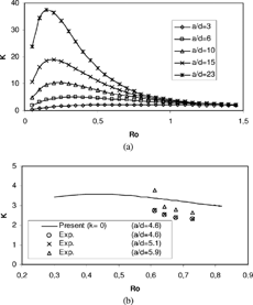
a shows the plot of Equation (Equation8) which is the characteristic curve of the pressure drop coefficient for a cyclone. Instead of α, the ratio a 0/a 3 = a 0/(0.1D 3m ) was selected as the third parameter in this figure, and symbolized as (a/d) due to its meaning. The parameter (a/d) determines the shape of the curve, as can be seen from the figure. When (a/d) is less than 3, the pressure drop coefficient remains nearly constant for a wide range of Ro, otherwise K increases and reaches to a maximum value at a critical point of Ro, and than decreases to the same asymptotic value of 1. An increase in (a/d) results in an increase in the pressure drop coefficient and a small decrease in the critical point of Ro. Due to the definition of the friction factor Ro, the critical value of Ro corresponds to a critical value of fo. Therefore, reduction of pressure drop can be achieved by keeping Ro or fo away from the critical point. Note also that the asymptotic value of K is 1 for all a/d (or α) values. This means that, with increasing friction factor, shortcut flows increase according to Equation (Equation4), eventually, frictional losses vanish, and entrance and exit losses become dominant which gives K → 1.
This figure also shows that K strongly depends on Ro in the region around its maximum value. This region becomes narrower and variation in K becomes stronger in the case of increasing the value of (a/d). Therefore, precise calculation of Ro or fo is required for smaller error in the calculation of K in this region. This will be achieved by the accurate determination of flow type, Reynolds number and relative roughness. Similar behavior seems to be presented by experimental results available in the literature (CitationXiang et. al. 2001) which agree with the computed values, as can be seen in b. But, additional experimental data covering entire range of Ro is needed for detail interpretation.
FIG. 3 Comparison of the computed pressure drop coefficient with the experimental values reported by (a) CitationXiang et al. (2001) and (b) CitationGriffiths and Boysan (1996).
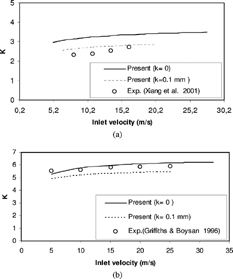
gives a comparison of the pressure drop coefficient predicted by the present model with experimental ones given in the literature, and shows the role of cyclone surface roughness. When surface roughness is assumed as k = 0.1 mm, the predicted pressure drop coefficient diminishes depending on the relative roughness, and much better agreement is obtained between the predicted values and experimental data for geometry 1 (a/d = 4.6), in a.
FIG. 4 Comparison of pressure drop between the predictions of five models and experimental data reported by (a) CitationXiang et al. (2001), geometry 1; (b) CitationPatterson and Munz (1989), geometry 2; (c) CitationLim et al. (2004), geometry 4; (d) CitationFassani and Goldstein (2000), geometry 7; (e) CitationGriffiths and Boysan (1996), geometry 8; (f) CitationKim and Lee (1990), geometry 9.
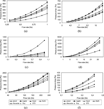
illustrates the evolution of pressure drop with inlet flow rate and comparison between experimental data taken from the literature and the predictions of five models including present study. As expected, pressure drop increased with increases in flow rates. In general, the agreement between the present model predictions and experimental data is acceptable for all cyclones, whereas the other models give relevant results only several cyclones. The reason is that, the proposed model includes the effects of surface roughness and Reynolds number which includes temperature effects implicitly, and almost all of the parameters (such as inlet and outlet geometries, shortcut flow, cone shape, etc.) which play important role on the pressure drop. However, the other models are either very simple and exclude many parameters or valid only for a certain cyclone for which were developed, and they do not give accurate results for other cyclones. and also compare the model results with the CFD simulations reported by CitationGriffiths and Boysan (1996).
CitationKim and Lee (1990) presented that the pressure drop was relatively small when the ratio of the vortex tube to cyclone body diameter (D 2/D 1) was between 0.5 and 0.6, and increased otherwise. The present model were tested when D 2/D 1 = 0.5 and 0.152 which correspond to the outlet pipe diameter of 23 mm and 7 mm, respectively. The predicted pressure drop values were compared with the experimental values given by CitationLim et al. 2004 (). As can be seen, the pressure drop is smaller when D 2/D 1 = 0.5. Although, the present model takes into account the outlet pipe diameter implicitly, the agreement between calculated pressure drops and experimental values is very good especially for D 2/D 1 = 0.152.
FIG. 5 Influence of the outlet pipe diameter on the pressure drop calculated in the present study and measured by CitationLim et al. (2004).
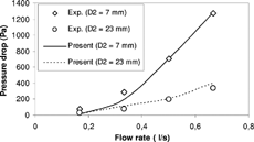
FIG. 6 Influence of temperature on the pressure drop. Comparison between data given by CitationBohnet (1995) and the predictions of five models (Geometry 10).
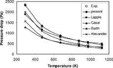
shows the calculated pressure drop obtained using the models and the experimental values measured by CitationBohnet (1995). The pressure drop decreases significantly with rising temperature, mainly due to the decrease of the density and increase of the viscosity of the gas. As can be seen from the figure, the present model gives quite good approximation of the pressure drop, comparing to the other models, since the present model includes Reynolds number which is a function of the temperature dependent properties, density and viscosity, of the fluid.
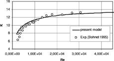
The dependence of the pressure drop coefficient K on the Reynolds number was calculated and given in , up to Re = 4 × 10⁴, for geometry 10. This range of Reynolds number was obtained by changing the flow rate and the temperature of the gas. According to this figure, the pressure drop coefficient increases with Re considerably at low Re and remains almost constant at high Re. The present model slightly over predicts the K at low Re mainly due to poor prediction of the friction coefficient in the transition regime and effect of surface roughness.
4. CONCLUSION
A new mathematical model presented in this article offers an easy and effective way to calculate pressure drop in a tangential inlet cyclone for a known geometry. The present model calculates the pressure drop from the frictional losses in the cyclone body. The entrance and exit losses are also included in the model by defining new geometrical parameters. The pressure drop coefficient is obtained as a function of cyclone dimensions and operating conditions. Despite the simple approximations to the friction coefficient and the vortex length, good agreement between the computed results and experimental values shows that the proposed model is successful for different cyclones comparing with other models given in the literature and can reduce experimental works for design and optimization of cyclones. The following general conclusions can be drawn from this work.
| 1. | Pressure drop coefficient (K) is not constant and found to be a function of cyclone dimensions and operating conditions. Moreover, the pressure drop coefficient has a maximum value which depends on the geometry, for each cyclone. | ||||
| 2. | In order to reduce pressure drop, the friction factor (R 0) should be far from its critical value which gives the maximum of K. | ||||
| 3. | The value of (a/d) also influences the pressure drop coefficient. Increase of this value causes narrower region where the pressure drop coefficient strongly depends on the friction factor and reaches a maximum point. Decreasing this value leads to a larger region and weaker variation in the pressure drop coefficient. | ||||
| 4. | Another important parameter is the friction coefficient which also affects the pressure losses. A critical value of the friction coefficient seems to be present for a known geometry, so that the friction coefficient smaller or bigger than this critical value leads to a decrease in the pressure drop. Therefore, Reynolds number and relative roughness are essential for accurate prediction of the friction factor. | ||||
| 5. | The pressure drop coefficient may be taken as constant for the cyclones which are either big and operated in a narrow velocity range or small but have high relative roughness. Otherwise, the effects of Reynolds number and relative roughness which is mostly omitted become more significant and should be considered in the models. | ||||
| 6. | In laminar region, the pressure drop coefficient is strongly influenced by operating conditions, due to linear dependency of the friction coefficient on the Reynolds number. | ||||
| 7. | One of the important problems is the definition of the Reynolds number. The present model with the defined Reynolds number predicts quite well the pressure drop. However, in the transition region, the friction coefficient may not be determined properly due to fact that the flow in this region may be laminar or turbulent depending on the specific circumstances involved. Therefore, different definitions of Reynolds number may be searched for the prediction of flow type and the friction coefficient correctly. | ||||
| 8. | The physical principal of the model can also be applied to the cyclones other than tangential inlet type cyclones, required that the parameters defined in the model (such as a, a d , D d , etc.) should be modified or redefined according to the inlet and outlet geometries of these cyclones. | ||||
| 9. | Further experimental and theoretical work is required for determination of influence of the dust outlet geometry on the modified cone apex diameter and also for deriving new relation of the vortex length, as a function of operating conditions and cyclone dimensions. | ||||
Notes
*The elliptical inlet of Geometry 9 was approximated as a rectangle with the same area.
REFERENCES
- Alexander , R. M. 1949 . Fundamentals of Cyclone Design and Operation . Proc. Aus. Inst. Min. Met. NS , 152–153 : 203 – 228 .
- Altmeyer , S. , Mathieu , V. , Jullemier , S. , Contal , P. , Midoux , N. , Rode , S. and Leclerc , J. P. 2004 . Comparison Of Different Models of Cyclone Prediction Performance for Various Operating Conditions Using a General Software . Chem. Eng. and Proc. , 43 : 511 – 522 . [CSA] [CROSSREF]
- Avci , A. and Karagoz , I. 2003 . Effects of Flow and Geometrical Parameters on the Collection Efficiency in Cyclone Separators . J. Aerosol Sci. , 34 : 937 – 955 . [CSA] [CROSSREF]
- Avci , A. and Karagoz , I. 2001 . Theoretical Investigation of Pressure Losses in Cyclone Separators . Int. Comm. Heat Mass Transfer , 28 ( 1 ) : 107 – 117 . [CSA] [CROSSREF]
- Barth , W. 1956 . Berechnung und Auslegung von Zyklonabscheiden auf Grund neuerer Untersuchungen . BWK , 8 : 1 – 9 . [CSA]
- Bohnet , M. 1995 . Influence of the Gas Temperature on the Separation Effeciency of Aerocyclones . Chem. Engin. Process. , 34 : 151 – 156 . [CSA] [CROSSREF]
- Casal , J. and Martinez-Benet , J. M. 1983 . A Better Way to Calculate Cyclone Pressure Drop . Chem. Eng. , : 99 – 108 . [CSA]
- Fassani , F. L. and Goldstein , L. Jr. 2000 . A Study of the Effect of High Inlet Solid Loading on a Cyclone Separator Pressure Drop and Collection Efficiency . Powder Technology , 107 : 60 – 65 . [CSA] [CROSSREF]
- Gil , A. , Romeo , L. M. and Cortés , C. 2002 . Effect of the Solid Loading on a Pressurized Fluidized Bed Combustors Cyclone with Pneumatic Extraction of Solids . Chem. Eng. Technol. , 25 : 407 – 415 . [CSA] [CROSSREF]
- Grane , R. L. , Barbaris , L. N. and Behrouzi , P. 1992 . Particulate Behavior in Cyclone Separators with Secondary Gas Extraction . J. Aerosol Sci. , 23 : 765 – 768 . [CSA] [CROSSREF]
- Griffiths , W. D. and Boysan , F. 1996 . Computational Fluid Dynamics (CFD) and Empirical Modelling of the Performance of a Number of Cyclone Samplers . J. Aerosol Sci. , 27 : 281 – 304 . [CSA] [CROSSREF]
- Gupta , A. K. , Lilley , D. C. and Syred , N. 1984 . Swirl Flows. , Abacus Press .
- Hoekstra , A. J. , Derksen , J. J. and Van Den Akker , H. E. A. 1999 . An Experimental and Numerical of Study Turbulent Swirling Flow in Gas Cyclones . Chem. Enginee. Sci. , 54 : 2055 – 2065 . [CSA] [CROSSREF]
- Hoffmann , A. C. , De Groot , M. , Peng , W. , Dries , H. W. A. and Kater , J. 2001 . Advantages and Risks in Increasing Cyclone Separator Length . AIChE J. , 47 : 2452 – 2460 . [CSA] [CROSSREF]
- Ingham , D. B. and Ma , L. 2002 . Predicting the Performance of Air Cyclones . Int. J. Energy Res. , 26 : 633 – 652 . [CSA] [CROSSREF]
- Ioza , D. L. and Leith , D. 1989 . Effect of Cyclone Dimensions on Gas Flow Pattern and Collection Efficiency . Aerosol Sci. Technol. , 10 : 491 – 500 . [CSA]
- Ioza , D. L. and Leith , D. 1990 . The Logistic Function and Cyclone Fractional Efficiency . Aerosol Sci. Technol. , 12 : 598 – 606 . [CSA]
- Jo , Y. , Tien , C. and Ray , M. B. 2000 . Development of a Post Cyclone to Improve the Efficiency of Reverse Flow Cyclones . Powder Technol. , 113 : 97 – 108 . [CSA] [CROSSREF]
- Kim , J. C. and Lee , K. W. 1990 . Experimental Study of Particle Collection by Small Cyclones . Aerosol Sci. Technol. , 12 : 1003 – 1015 . [CSA]
- Kim , H. T. , Lee , K. W. and Kuhlman , M. R. 2001 . Exploratory Design Modifications for Enhancing Cyclone Performance . J. Aerosol Sci. , 32 : 1135 – 1146 . [CSA] [CROSSREF]
- Lapple , C. E. 1951 . Processes use Many Collector Types . Chem. Engineering , 58 : 144 – 151 . [CSA]
- Lim , K. S. , Kim , H. S. and Lee , K. W. 2004 . Comparative performances of Conventional Cyclones and a Double Cyclone with and without an Electric Field . J. Aerosol Sci. , 35 : 103 – 116 . [CSA] [CROSSREF]
- Lorenz , T. 1994 . Heissgasentstaubung mit zyklonen . VDI-Fortschrittsberichte , 3 : 1 – 113 . [CSA]
- Mothes , H. and Löffler , F. 1988 . Prediction of Particle Removal in Cyclone Separators . Int. Chem. Engng. , 28 : 231 – 240 . [CSA]
- Muschelknautz , E. 1970 . Auslegung Von Zyklonabscheidern in Der Technischen Praxis, Staub Reinhalt . Luft , 30 : 187 – 195 . [CSA]
- Patterson , P. A. and Munz , R. J. 1989 . Cyclone Efficiencies at Very High Temperatures . Can. J. Chem. Eng. , 67 : 321 – 328 . [CSA]
- Saltzman , B. E. and Hochstrasser , J. M. 1983 . Design and Performance of Miniature Cyclones for Respirable Aerosol Sampling . Environ. Sci. Technol. , 17 : 418 – 424 . [CSA] [CROSSREF]
- Stairmand , C. J. 1949 . Pressure Drop in Cyclone Separators . Engineering , : 409 – 417 . [CSA]
- Stairmand , C. J. 1951 . The Design and Performance of Cyclone Separators . Trans Inst. Chem. Eng. , 29 : 356 – 383 . [CSA]
- Shepherd , G. B. and Lapple , C. E. 1939 . Flow Pattern and Pressure Drop in Cyclone Dust Collectors . Ind. Engng. Chem. , : 31 [CSA]
- Upton , S. L. , Mark , D. , Hall , D. and Griffiths , W. D. 1994 . A Wind Tunnel Evaluation of the Sampling Efficiencies of Three Bioaerosol Samplers . J. Aerosol Sci. , 25 : 1493 – 1501 . [CSA] [CROSSREF]
- Xiang , R. , Park , S. H. and Lee , K. W. 2001 . Effects on Cone Dimension on Cyclone Performance . J. Aerosol Sci. , 32 : 549 – 561 . [CSA] [CROSSREF]
- Yoshida , H. , Fukui , K. , Yoshida , K. and Shinoda , E. 2001 . Particle Separation by Iinoya's Type Gas Cyclone . Powder Technol. , 118 : 16 – 23 . [CSA] [CROSSREF]
- Zhu , Y. and Lee , K. W. 1999 . Experimental Stuady on Small Cyclones Operating at High Flow Rates . J. Aerosol Sci. , 30 : 1303 – 1315 . [CSA] [CROSSREF]
