An axisymmetric turbulent air jet flow (with vertical and downward orientation) laden with fluorescent solid particles was impinged normally onto a flat surface. The particle deposition efficiency and distribution on the flat surface were measured experimentally using fluorometry and imaging techniques. The fluorescent particles (5.0 μm diameter) were dispersed by a nebulizer and injected in a stream of compressed air, resulting in a steady flow (Q = 111 L/min). A round nozzle was used to generate a jet characterized by a Reynolds number of Re = 10 4 , based on the nozzle diameter (D = 15.0 mm) and nozzle exit velocity (u = 10.5 m/s). Three dimensionless distances from the nozzle's exit to the impaction surface, L/D = 2, 4, and 6, were investigated. It was observed that although having similar total deposition efficiencies (16.5–17.8%), shorter nozzle to surface distances (L/D = 2 and 4) show a more pronounced ring-like radial deposition pattern around the stagnation point. These shorter distances also exhibit significantly lower particle deposition near the stagnation point when compared to the longer distance (L/D = 6). Indeed, in moving through L/D = 2, 4, and 6, peak deposition density values of 254, 347, and 685 particles/mm 2 shift through radii of 2.1 D, 0.8 D, and 0.1 D, respectively. In addition to the experiments, numerical simulation was also performed, which showed that the particle deposition was dominated by a turbulent dispersion mechanism for L/D = 2, with inertial impaction becoming more important for the L/D = 4 and 6 cases.
INTRODUCTION
Single-phase turbulent impinging jets produce high levels of heat and mass transfer in the stagnation region, having many industrial applications, for example, internal cooling of gas turbine blades, cooling of electronic devices, and paper drying. Solid or liquid particle laden impinging jets also have various applications, ranging from inkjet printing, painting, sand blasting, surface erosion and pharmaceutical aerosols, among others. Hitherto, single-phase impinging jets have been further studied both experimentally (CitationCooper et al. 1993; CitationNishino et al. 1996) and numerically (CitationCraft et al. 1993; CitationLaunder 1996) when compared with particle laden impinging jets (CitationAnderson and Longmire 1995; CitationSethi and John 1993).
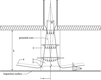
According to CitationJambunathan et al. (1992), an impinging jet can be reduced to four major zones: (1) the initial mixing zone, (2) the established zone, (3) the deflection zone, and (4) the wall jet (see ). L is the nozzle-to-surface distance, D is the nozzle diameter, r is the radial distance from the stagnation point of the jet on the impingement wall and z is the distance upward from the impingement wall. As the flow exits the nozzle, a constant velocity profile is apparent across most of the jet, with the exception of the edges, where the velocity falls off rapidly due to the no-slip condition. With increasing distance towards the impingement plate (further distance from the nozzle), the jet begins to develop, widening and diverging from a constant top hat profile as the jet entrains stationary fluid from around the edges into the stream. A conical shaped region, labelled as the potential core in , is characterized by a radially independent velocity profile. At the tip of the cone, where there is no longer a region of constant velocity across the cross-section of the jet, the jet is said to be fully developed. The distance from the nozzle at which this occurs is called the core length. The region between the nozzle and the core length is the initial mixing zone. After this point, the jet continues to spread out in the radial direction in the established zone. As the jet approaches the impingement surface, boundary layer effects occur and the jet's streamlines begin to diverge from the central axis in the deflection zone. Boundary layer effects dominate and the flow is forced parallel to the impingement surface. This is also the region of greatest interest for particle impaction. The inertia of the particles in the flow carry them out of the fluid's streamlines and, if they posses enough inertia, onto the impaction surface. Particle deposition in the present geometry has been well studied at low Reynolds numbers because of interest in cascade impactor design (see, e.g., CitationMarple et al. 2001; CitationGómez-Moreno et al. 2002 and references therein). While few studies have examined the spatial distribution of particle deposition on the impaction surface (CitationSethi and John 1993), to the authors' knowledge, no studies have been published on the spatial distribution of particle deposition at higher Reynolds numbers in the present geometry. While such work is of little interest to impactor jet design, since high Reynolds numbers reduce the sharpness of the cut-off curves, it is of interest in developing a fundamental understanding of turbulent particle deposition in canonical geometries. The present work is a step in this direction. Such understanding is needed if numerical models of deposition, which have difficulty accurately predicting particle deposition in complex turbulent flows, are to be improved.
FIG. 1 Impinging jet schematic, depicting the 4 regions: (1) Mixing Region, (2) Established Region, (3) Deflection Region, and (4) Wall Jet Region.
In the present work, a confined jet laden with particles of 5.0 μm diameter is impinged on a flat surface geometry at Re = 104, and the total particle deposition efficiency and spatial distribution are measured experimentally and simulated numerically for different nozzle-to-surface distances.
EXPERIMENTAL METHODS
Fluorescent Particles
Solid fluorescent particles (model G0500B, Duke Scientific, Inc.) used in the described work were monodisperse polystyrene microspheres (ρ p = 1.05 g/cm 3 , d p = 5.0 μm). The particles were packaged as 1% solids suspended in a multi component dispersing system to prevent aggregation. In the aqueous suspension, there were 1.5× 10⁸ particles/mL. The particle Stokes Number (CitationMarple et al. 2001), is defined as:
Aerosol Generation
shows the generation setup for the jet laden with fluorescent particles. Air from a compressor entered the nebulizer (Model LC Star, Pari Respiratory Equipment, Inc., Starnberg, Germany) which created an aerosol of the fluorescent particles. The aerosol then entered the primary mixing chamber through the hose from the nebulizer (Q 1), denoted as the primary air flow. Also entering the primary mixing chamber was a secondary air flow at a much larger rate (Q 2). Both the primary and secondary flows were measured using a standard flow meter (FL-Series Flow Meter, Omega) in units of SCFM (1SCFM = 28.3 L/min = 4.72 × 10− 4 m3/s). The primary and secondary air flows were held constant for every trial and were set to achieve a Reynolds number of Re = 10000 ± 256 at the nozzle exit. The primary air flow from the compressor was measured to be Q 1 = 13 ± 1 L/min while the secondary air flow was Q 2 = 98 ± 1 L/min. Thus the flow rate at the nozzle exit was Q 3 = Q 1 + Q 2 = 111 ± 2 L/min.
FIG. 2 Nebulizer and impinging jet set up schematic for aerosol creation, neutralization, and acceleration into the deposition chamber.
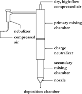
As the aerosol moved into the primary mixing chamber, it mixed with the dry air from the secondary air flow. During this mixing, the water present in the aerosol evaporated, leaving the dry fluorescent particles moving through the stream. Because the mass median aerodynamic diameter of the droplets produced by the nebulizer is known to be similar to the size of the fluorescent particles, the probability of creating doublet or triplet particles is negligible (CitationFinlay et al. 1997). The particles then passed though the charge neutralizer (Model 3454, TSI, Inc.) in order to minimize electrostatic effects in the deposition process. A secondary mixing chamber was included to allow mounting of the nozzle and to allow for a range of nozzle-to-surface distance to be investigated. After the aerosol passed through the secondary mixing chamber, it was accelerated through the nozzle and into the deposition chamber.
Impinging Jet Deposition Apparatus
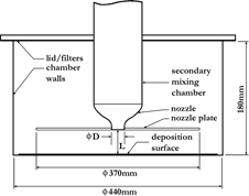
A schematic of the confined jet and the deposition chamber is shown in . The deposition chamber consisted of an open top transparent acrylic cylinder with an inner diameter of 440 mm and a height of 180 mm. The top was covered during the trials with an aluminum lid, with holes for the air to flow out of. These exit holes were placed at a constant radius around the center of the lid approximately half way between the center and edge. The holes were covered with filters (Model par41f05, Pari Respiratory Equipment, Inc., Starnberg, Germany) to keep the particles from contaminating the laboratory. There was also a hole in the center of the lid lined with a rubber o-ring where the nozzle and secondary mixing chamber could slide through. This allowed for the nozzle-to-surface distance, L, to be altered and set easily. A nozzle plate with a diameter of 370 mm was attached to the nozzle to act as a flow guide and to protect the impinging jet and impingement surface from the re-entrainment of flow that had already past by the deposition surface.
FIG. 3 A side-view schematic of the deposition chamber, showing the design specifications of the chamber, nozzle plate, lid with filters and the implementation of the nozzle and mixing chamber mechanism into the deposition chamber.
The deposition surface was a circular sheet of overhead transparency plastic (Type 787, AGFA) secured to the bottom of the deposition chamber. The sheets were charge neutralized before the procedure was started.
The nebulizer was filled with 9 mL of water and 1 mL of the 1% solid particle-water suspension. The nebulizer compressor was started and allowed to run until the nebulizer was empty, which was approximately 50 minutes.
For the present work, three different L/D values were investigated. The different L/D cases were each repeated three times separately, and one radial ray from the stagnation point outward was analyzed for each repetition. The particle size was held constant throughout the entire process (d p = 5.0 μm), as was the nozzle exit Reynolds number (Re = 104) and the nozzle diameter (D = 15.0 mm).
Imaging
The use of fluorescent particles enables the visualization of the deposited patterns. These particles have an excitation maximum of λ = 468 nm and an emission maximum of λ = 508 nm. Short wavelength UV light was used to excite the particles and allowed for visualization of the patterns. Using a microscope equipped with a digital camera and the appropriate laser for excitation, close up images of the patterns were captured and analyzed. An image processor (Scion Image, Scion Corporation) with particle identification capabilities allowed for the individual close up images of the impaction surface to be assigned a particle deposition density. This was accomplished with the knowledge of the total number of particles in the image (acquired from the image processor) and the physical dimensions of the surface captured in the image, which was easily determined through calibration of the microscope-camera system. By taking images at specified distances from the center of the pattern (found by identifying the point on the pattern directly below the center of the nozzle) a profile for the deposition of particles from the stagnation point outward was compiled. The surfaces were imaged outward every 2 mm successively from the stagnation point until the deposition was negligible.
Fluorometry
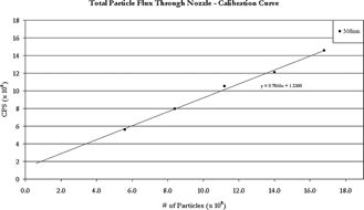
The impactor efficiency can be defined as the ratio of the mass of particles deposited on the surface to the total mass of particles leaving the nozzle. Since the particles are the same size and density, the ratio can be reduced to a number ratio, for example, the total number deposited on the surface versus the total number of particles leaving the nozzle. To find the number of particles leaving the nozzle, a filter was attached to the nozzle and a run was performed as usual. All of the particles that left the nozzle collected in the filter to be analyzed. The filter was soaked in chloroform to dissolve the dye (and the entire particle itself). This was necessary as the dye must be in solution, not suspension, for proper analysis in the fluorometer (Fluoromax, Spex Industries, Edison, New Jersey). With all of the dye from the filter in solution, the emission intensity was compared to that of known dye concentrations, thus giving the amount of particles that deposited in the filter. The calibration curve for the fluorometry, defined using the emission intensities from several different known concentrations, is displayed in . The emission intensity, in counts per second (CPS) is on the vertical axis and the number of particles in solution needed to give that emission intensity is on the horizontal axis. The CPS was recorded at the dye's emission maximum, λ = 508 nm. The curve was initially found for a much larger domain, but only the linear region was used for the calibration. The CPS from the filter test case solutions can be converted via to find the number of particle present in the solution. The number of particles in the solution was then used to calculate the total number of particles that were trapped in the filter and thus, the total number of particles that left the nozzle. To determine the total number of particles which actually deposit on the impingement surface, the density profile curve found in the imaging process can be integrated about the circular two-dimensional surface it characterizes. This value and the value for the total number of particle that left the nozzle can be compared to give the efficiency of deposition.
NUMERICAL METHODS
Geometry, Conditions and Models
The flows through each of the three geometries investigated in this study were also solved numerically, using a computational fluid dynamics package (CFX5.7.1, Ansys, Inc.). A 3D structured multi-block mesh of 0.75 × 10⁶, 1.5× 10⁶, and 2.25 × 10⁶ nodes were used in the modelling of the L/D = 2, 4, and 6 cases respectively. Each of these meshes contained 13 blocks. Nodes were accumulated at the bottom, top and side wall surfaces. Mesh nodes were also accumulated in a cylindrical region having a diameter of 2D at the center of the geometry sharing its axis with the impinging jet. This enclosed the entire jet-core region, from the nozzle to the stagnation point. Discontinuities in node spacing at the block boundaries were avoided to ensure smooth connections. Grid convergence analysis using coarser (0.5 × 10⁶ nodes) and finer (1.0 × 10⁶ nodes) grid sizes for L/D = 2 showed the adopted grid (0.75× 10⁶ nodes) to be adequate, since the magnitude of mean velocities and turbulence kinetic energy differed by less than 1.6% between the two finest grids along the jet axis. Meshes containing similar spatial resolution were constructed for L/D = 2, 4, and 6, resulting in 0.75× 10⁶, 1.5× 10⁶, and 2.25× 10⁶ nodes, respectively. The Shear Stress Transport (SST, CitationMenter, 1994) turbulence model was used along with a second-order discretization scheme. For the inlet conditions, top hat profiles giving a steady flow rate of 111 L/min, a turbulence intensity of 5% of the mean velocity and a turbulence length scale of 10% of the inlet diameter were used.
In the Lagrangian particle tracking, particles were modeled to be solid, having a radius of 5 μm and a density of 1050 kg/m3. The flow rate was specified as 2.0 × 10− 9 kg/s, the particle mass flow rate used in the experiments. During one iteration, 10,000 particles were released. One-way coupling was used to govern the particle-fluid interaction in the multiphase flow.
RESULTS AND DISCUSSION
The impaction surface particle density profiles for the three L/D cases are plotted versus radial distance from the stagnation point in . For each case, the maximum deposition occurs not at the stagnation point but at some radius r max, where r max increases with decreasing L/D. Values of r max and corresponding deposition density are given in for each L/D. For L/D = 2 there is a large central region near the stagnation point with no appreciable deposition. Deposition in the central region (r < 0.67D) increases dramatically with increasing L/D.
FIG. 5 Plot of deposition density (particles/mm2) versus the non-dimensional distance outward from the stagnation point of the impinging jet flow for the three L/D values L/D = 2, 4, and 6. Each point is the average of three repeats. The curves are presented for visualization purposes. Standard error plus the error accumulated with the image processing is ±11%, while the error in the non-dimensional distance due to standard error and error in the location of the stagnation point is ±0.067 (±1 mm).
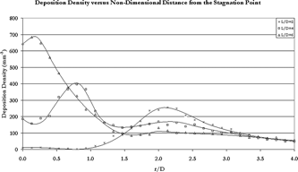
TABLE 1 The location outward from the stagnation point (r max) and density (ρmax) of the point of maximum deposition of each trial performed (average of three repeats, ± standard error, and error contributions by software)
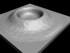
The lack of central deposition for L/D = 2 is clearly seen in which shows a top-view image of the deposition pattern. For visualization purposes, shows a three-dimensional rendering of with the height representing relative deposition density. The axisymmetry of the deposition is apparent.
FIG. 6 The experimental deposition pattern for L/D = 2, as seen from above. The darker regions are areas of low deposition, and the lighter regions are areas of high deposition.
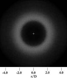
FIG. 7 The experimental deposition pattern shown in for L/D = 2, but rendered in three dimensions with the height corresponding to the relative deposition density profile.
Each of the three cases, L/D = 2, 4, and 6, exhibited similar qualitative patterns for deposition. An obvious ring shape was common to L/D = 2 and 4, with the pattern for L/D = 6 exhibiting a very tight ring shape but with large deposition at the center, unlike that of the previous two cases. All three were axisymmetric about the stagnation point, as expected.
lists the total number of particles that left the nozzle for each L/D as well as the total number of particles depositing, and the resulting deposition density. The average number of particles that deposited on the sheet shows a slight upward trend for an increasing nozzle-to-surface distance L/D.
TABLE 2 The total number of particles that left the nozzle, deposited on the impaction surface and resulting deposition efficiency for each of the three cases
Insight into the mechanism of deposition in this flow can be obtained by comparing deposition in the numerical simulations using “turbulent tracking” (i.e., with an eddy interaction model) versus “mean flow tracking” (i.e., with turbulent dispersion artificially turned off). With “turbulent tracking,” deposition is higher than with “mean flow tracking” by a factor of 1500, 5.2, and 15.1 for L/D = 2, 4, 6. This suggests that turbulent dispersion is many times more important than mean-flow inertial impaction in causing deposition (since for “mean flow tracking” the only deposition mechanism is inertial impaction). This result also suggests that the dominance of turbulent dispersion in causing deposition is extraordinarily pronounced at L/D = 2, and less so at the other values of L/D.
The prominence of turbulent dispersion as the principal deposition mechanism is further supported by comparing deposition patterns for the “turbulent tracking” and “mean flow tracking” simulations. shows simulated fluxes of particle deposition using “turbulent particle tracking,” where a ring-like deposition pattern is seen as in the experiments. The turbulent tracking simulations also have the area of larger deposition density moving towards the stagnation point as L/D was increased. This agrees with the experimental deposition patterns observed. In contrast, deposition patterns with “mean flow tracking” were concentrated in the stagnation region and did not show a ring-like pattern. Thus, the presence of turbulent dispersion in the simulations appears to be responsible for the ring-like deposition seen in the experiments.
FIG. 8 Bottom surface of deposition chamber after simulation with particle tracking for L/D = 2, 4, and 6. The plotted variable is the particle's wall stress, interpreted as deposition.

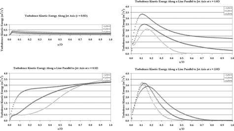
Further insight into the effect of turbulence on the particles can be obtained by examining the flow field. The simulation results for the magnitude of mean velocity and turbulence kinetic energy near the stagnation point (dimensionless distance from the impaction surface, z/D < 2, and dimensionless distance from the jet axis, r/D < 2.5) are shown in for L/D = 2, 4 and 6. Longer nozzle-to-surface distances allow the nozzle jet to spread before impinging on the surface, having a more developed potential core velocity and wider regions of pronounced turbulence kinetic energy. shows the turbulence kinetic energy along a line perpendicular to the jet axis (parallel to the impaction surface), and at a distance of z = 0.1 D above the impaction surface. It can be seen that the level of turbulence kinetic energy in this near-wall region is much larger in the L/D = 6 case and drops as the nozzle-to-surface distance is decreased. also shows that the turbulence kinetic energy increases as the distance from the axis, r/D, is increased, reaches different peaks (for different L/Ds) and then starts decreasing, suggesting a ring-like deposition pattern. Plots of the turbulence kinetic energy along lines running perpendicular to the impaction surface (parallel to the jet axis) are shown in for distances of r = 0.0 D, 0.5 D, 1.0 D, and 2.0 D. The turbulence kinetic energy for L/D = 6 is much larger than L/D = 4 and 2, for both r = 0.5 D, 1.0 D, at regions relatively away from the wall (z/D < 1). For all three values of L/D, deposition on the wall (seen in ) occurs in regions near or just past the regions of high turbulence kinetic energy, corroborating the hypothesis that turbulent dispersion is the major deposition mechanism.
FIG. 9 Simulation results for the Velocity (left column) and Turbulence Kinetic Energy (right column) in the stagnation region for L/D = 2, 4, and 6. r/D = 0 corresponds to the impinging jet's axis.
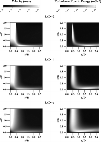
FIG. 10 Plot of the simulated Turbulence Kinetic Energy along a line perpendicular to the jet axis (parallel to the impaction surface) and located at a distance of z = 0.1D from the surface for L/D = 2, 4, and 6. Zero corresponds to the stagnation point.
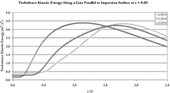
FIG. 11 Plots of the simulated Turbulence Kinetic Energy at various distances from the jet axis, along a line parallel to the jet axis. The data was taken from the impaction surface upwards for L/D = 2, 4, and 6.
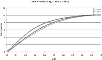
The simulation results also suggest that the particle deposition pattern is related to the development stage of the impingement jet (due to the distance between the nozzle and the impaction surface), giving differences in the magnitude of mean velocities and turbulence kinetic energy surrounding the stagnation point. shows the axial velocity along the jet axis for the three cases, demonstrating how the flow velocities differ in the region near the impingement wall. The larger axial velocities near to the impingement wall of the L/D = 4 and 6 cases would result in particles being carried closer to the wall and thus more likely to deposit due to turbulent dispersion, if not by inertial impaction.
FIG. 12 Plot of the simulated Axial Velocity (positive downward) along the jets axis from the impaction surface upward for L/D = 2, 4, and 6.
While the numerical simulations suggest that turbulent dispersion plays the primary role in particle deposition in the experiments, particularly for smaller L/D values, it should be noted that eddy interaction models overestimate deposition due to their assumption of an isotropic decomposition of turbulence in the standard random-walk model (CitationMatida et al. 2003). The present case appears to be no exception in this regard: total deposition values of T.D. = 75.0%, 77.4%, and 80.2% for L/D = 2, 4, and 6, respectively were obtained in the turbulent tracking simulations.
It should also be pointed out here that by gradually increasing the Stokes number (or particle size if the inlet nozzle velocity is kept constant), inertial effects would become sharply more dominant at a certain Stokes number (i.e., at the cut-off Stokes number) and influence the deposition patterns as described by CitationSethi and John (1993). By changing the L/D value, this cut-off Stokes number is shifted; the cut-off Stokes number decreases when the L/D value is increased and all other parameters held constant (CitationMarple et al. 2001). However, the low experimental deposition efficiencies (16.5–17.8%) indicate that the Stokes number was below the corresponding cut-off Stokes numbers for each of the cases investigated here.
CONCLUSION
Through the use of fluorescent tagging, the deposition of particles entrained in an impinging jet was studied qualitatively, quantitatively and numerically. The deposition patterns of various L/D values were investigated with all other parameters, including the Reynolds number at the nozzle and Stokes number, held constant. The patterns which emerged from the deposition cases were all circularly symmetric about the stagnation point and they all exhibited a ring-like form. It was found that the distance from the stagnation point to the location of maximum deposition for each pattern decreased with increasing L/D. For L/D = 6, the maximum deposition occurred almost at the stagnation point, with a small ‘divot’ in the density right at the stagnation point. For L/D = 4, the maximum occurred further from the stagnation point, still with an appreciable amount of deposition in the stagnation region. For the smallest nozzle-to-surface distance investigated, L/D = 2, there was very little deposition in the stagnation region and the maximum deposition occurred furthest from the stagnation point when compared to the previous two cases. It was also found that the amount of deposition that occurred in central regions became larger with increasing L/D. A similar peak is seen in heat transfer results (CitationCooper et al. 1993; CitationBaughn and Shimizu 1989) at two nozzle diameters from the stagnation point for the most pronounced (L/D = 2) case.
The numerical study revealed that the deposition of the particles was strongly a result of turbulent dispersion for the L/D = 2 case, with nearly no inertial deposition. Inertial impaction becomes more important in particle deposition for the L/D = 4 and L/D = 6 cases. The findings of the numerical work showed that each of the three cases had an area of high turbulence kinetic energy, at z = 0.1 D above the impaction surface, which became closer to the stagnation point for larger L/D values. The particle tracking technique used here agreed with the conclusion that turbulent dispersion was an important factor, as the fate of nearly all particles released in the three simulations deposited on the bottom wall near or just past these regions of high turbulence kinetic energy. The methods developed in this work describe an approach to visualizing deposition by particle-laden flows that can be applied to further work aimed at better understanding particle deposition in turbulent flows.
Acknowledgments
The loan of the fluorometer by R. Loebenberg is gratefully appreciated.
REFERENCES
- Anderson , S. L. and Longmire , E. K. 1995 . Particle Motion in the Stagnation Zone of an Impinging Air Jet . J. Fluid Mech. , 299 : 363 – 366 . [CSA]
- Baughn , J. W. and Shimizu , S. 1989 . Heat Transfer Measurements from a Surface with Uniform Heat Flux and an Impinging Jet . Trans. ASME , 111 : 1096 – 1098 . [CSA]
- Cooper , D. , Jackson , D. C. , Launder , B. E. and Liau , G. X. 1993 . Impinging Jet Studies for Turbulence Model Assessment-I. Flow-Field Experiments . Int. J. Heat Mass Trans. , 36 ( 10 ) : 2675 – 2684 . [CROSSREF] [CSA]
- Craft , T. J. , Grahan , J. W. and Launder , B. E. 1993 . Impinging Jet Studies for Turbulence Model Assessment—II. An Examination of the Performance of Four Turbulence Models . Int. J. Heat Mass Trans. , 36 ( 10 ) : 2685 – 2697 . [CROSSREF] [CSA]
- Finlay , W. H. , Stapleton , K. W. and Zuberbuhler , P. 1997 . Predicting Lung Dosages of a Nebulized Suspension Pulmicort® (Budesonide) . Particulate Sci. Technol. , 15 : 243 – 251 . [CSA]
- Gómez-Moreno , F. J. , Rosell Llompart , J. F. and Fernández de la Mora , J. 2002 . Turbulent Transition in Impactor Jets and its Effect on Impactor Resolution . J. Aerosol Sci. , 33 : 459 – 476 . [CROSSREF] [CSA]
- Jambunathan , K. , Lai , E. , Moss , M. A. and Button , B. L. 1992 . A Review of Heat Transfer Data for Single Circular Jet Impingement . Int. J. Heat and Fluid Flow , 13 : 106 – 115 . [CROSSREF] [CSA]
- Launder , B. E. 1996 . “ Turbulence and Transition Modeling ” . Edited by: Hallback , M. 193 Netherlands : Kluwer Academic Publishers . Ch. 5
- Matida , E. A. , DeHaan , W. , Finlay , W. H. and Lange , C. F. 2003 . Simulation of Particle Deposition in an Idealized Mouth with Different Small Diameter Inlets . Aerosol Sci. Technol. , 37 : 924 – 932 . [CROSSREF] [CSA]
- Marple , V. A. , Olson , B. A. and Rubow , K. L. 2001 . “ Inertial, Gravitational, Centrifugal and Thermal Collection Techniques ” . In Aerosol Measurement: Principles, Techniques and Applications , 2nd ed. Edited by: Baron , P. A. and Willeke , K.
- Menter , F. R. 1994 . Two-Equation Eddy-Viscosity Turbulence Models for Engineering Applications . AIAA J. , 32 ( 8 ) : 1598 – 1605 . [CSA]
- Nishino , K. , Samada , M. and Torii , K. 1996 . Turbulence Statistics in the Stagnation Region of an Axisymmetric Impinging Jet Flow . Int. J. Heat and Fluid Flow , 17 ( 3 ) : 193 – 201 . [CROSSREF] [CSA]
- Sethi , V. and John , W. 1993 . Particle Impaction Patterns from a Circular Jet . Aerosol Sci. Technol. , 18 ( 1 ) : 1 – 10 . [CSA]
