This work thoroughly analyzes a new commercial instrument for measuring Cloud Condensation Nuclei (CCN), the Droplet Measurement Technologies Cylindrical Continuous-Flow Streamwise Thermal Gradient CCN Chamber (CFSTGC). This instrument can measure CCN concentrations at supersaturations from 0.06% to 3% (potentially up to 6%), at a 1 Hz sampling rate that is sufficient for airborne operation. Our analysis employs a fully coupled numerical flow model to simulate the water vapor supersaturation, temperature, velocity profiles and CCN growth in the CFSTGC for its entire range of operation (aerosol sample flow rates 0.25–2.0 L min − 1 , temperature differences 2–15 K and ambient pressures 100–1000 mb). The model was evaluated by comparing simulated instrument responses for calibration aerosol against actual measurements from an existing CCN instrument. The model was used to evaluate the CCN detection efficiency for a wide range of ambient pressures, flow rates, temperature gradients, and droplet growth kinetics. Simulations overestimate the instrument supersaturation when the thermal resistance across the walls of the flow chamber is not considered. We have developed a methodology to determine the thermal resistance and temperature drop across the wetted walls of the flow chamber, by combining simulations and calibration experiments. Finally, we provide parameterizations for determining the thermal resistance, the instrument supersaturation and the optimal detection threshold for the optical particle counter.
1. INTRODUCTION
The fraction of aerosol that can become droplets in ambient clouds is known as Cloud Condensation Nuclei (CCN). Knowledge of CCN concentrations is fundamentally important for aerosol-cloud-climate interaction studies, because it provides the direct quantitative link between aerosol and clouds. Thermodynamic theory (Köhler 1936) predicts the minimum supersaturation required for a particle to “activate” (or to become a cloud droplet), also known as the particle “critical supersaturation.” The theory requires knowledge of particle chemical composition and dry particle size. In the presence of soluble gases, the composition of the gas phase may also be required. Although aerosol microphysical properties (such as particle size distribution and number concentration) can be measured rapidly, complete chemical analysis is more challenging due to the complexity and variability of ambient aerosol (CitationSaxena and Hildemann 1996). When the physicochemical properties of the aerosol are unknown or incomplete, CCN concentrations are not available from theory and must be measured by exposing particles to a controlled water vapor supersaturation and counting the droplets that form. Observations of CCN are important for evaluating and constraining regional and global aerosol models, as well as global climate modeling simulations of the aerosol indirect effect. CCN measurements are also important for use with aerosol of known composition to study unresolved chemical effects and to test the theories regarding aerosol-cloud interactions.
Instruments that measure CCN can be classified by how they generate water vapor supersaturation, based on (1) the nonlinear dependence of water vapor pressure upon temperature, or (2) the difference between water vapor diffusivity and thermal diffusivity. The first type have an applied temperature gradient perpendicular to the flow and include Static Diffusion Cloud Chambers (SDCC) (CitationTwomey 1963; CitationLala and Jiusto 1977), Continuous Flow Parallel Plate Diffusion Chambers (CFDC) (CitationSinnarwalla and Alofs 1973; CitationFukuta and Saxena 1979; CitationVan Reken et al. 2004), the Hudson CCN spectrometer (CitationHudson 1989), and the CCN remover (CitationJi et al. 1998). The second type requires continuous, laminar flow, and a temperature gradient that is in the streamwise direction (CitationHoppel et al. 1979; CitationChuang et al. 2000; CitationRoberts and Nenes 2005; CitationRogers and Squires 1977). Most designs operate on the principle of activating CCN and measuring the resulting droplet size distribution; the only exception is the CCN remover (CitationJi et al. 1998), which measures the interstitial (i.e., unactivated) aerosol particles instead. Most instruments count CCN at one supersaturation; the “spectrometer” designs (CitationHudson 1989; CitationFukuta and Saxena 1979; CitationVan Reken et al. 2004) simultaneously measure over multiple supersaturations. CitationHudson (1989) report a dynamic supersaturation range of 0.01–2.0%. Their design infers critical supersaturation from the droplet growth inside the instrument and is sensitive to changes in the growth kinetics from the presence of film-forming or slowly dissolving compounds (CitationNenes et al. 2001). Compared to CitationHudson (1989), the CitationFukuta and Saxena (1979), and CitationVan Reken (2004) designs operate in a narrower dynamic range (0.1–1.0% for the former and 0.07–1.2% for the latter) but are much less sensitive to variations on droplet growth kinetics. The CCN “counter” designs operate roughly within the 0.1–2.0% supersaturation range and are insensitive to compositional effects. A theoretical analysis for many of these designs can be found in CitationNenes et al. (2001).
Droplet Measurement Technologies (DMT; www.dropletmeasurement.com) has developed a new CCN counter based on the design of CitationRoberts and Nenes (2005), which generates supersaturation in an axisymmetric flow by applying a constant temperature gradient in the streamwise direction. This approach was also independently explored by CitationRogers and Squires (1977). The instrument, like other prior designs (e.g., CitationHoppel et al. 1979; CitationChuang et al. 2000), rely on the dissimilarity between heat and water vapor diffusivity to generate supersaturation. The goal of this study is to fully characterize and map the performance of the DMT design for the functional range of operating conditions, using computational fluid dynamics software in combination with measured instrument responses to single-component laboratory-generated aerosol.
2. INSTRUMENT DESCRIPTION
The DMT Continuous-Flow Streamwise Thermal-Gradient CCN Counter (CFSTGC, ) is designed to operate on a ground-based or airborne platform and can generate supersaturations between 0.06% and 3%. An ambient sample is introduced into the instrument, split into “sheath” and “aerosol” flows (typically with a sheath-to-aerosol flow ratio of 10). The sheath flow is filtered, humidified and heated, and provides a particle-free “blanket” of air within the CCN column that constrains the particles to the centerline of the flow chamber. The cylindrical column measures 0.5 m in length, with an 11.5 mm inner radius and a wall thickness of 10.0 mm. The inner wall of the CCN column is wetted continuously by supplying 4 mL hr− 1 (at the default “low” flow setting) of water onto a 2.5 mm thick porous ceramic material that lines the inner wall of the column. A positive temperature gradient is applied to the CCN column in the streamwise direction; the column is vertically oriented, with the flow moving from top to bottom. Water vapor supersaturation is generated within the CCN column, where the particles grow by condensation. Particles are considered droplets when they are large enough for detection by an optical particle counter (OPC) at the exit of the CCN column. The lowest size bin spans from 0.5 μ m to 0.75 μ m, but the control software allows for a larger “detection threshold” that is typically set to the 0.75–1.0 μ m size bin.
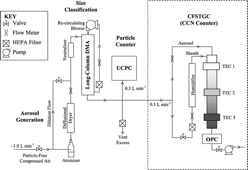
FIG. 1 Schematic of the CFSTGC calibration setup. A schematic of the CFSTGC is also shown within the dotted line.
To generate supersaturation, the CFSTGC requires a temperature gradient in the streamwise direction and a continuous, laminar flow. When the flow is fully developed, heat and water vapor are transported in the radial direction by diffusion. Water vapor that is saturated with respect to the wall temperature diffuses faster than heat; thus the flow region is supersaturated with water vapor, since water vapor is continuously exposed to temperatures lower than at the wall (CitationRoberts and Nenes 2005). Supersaturation is quasi-parabolic for a cross section of the CCN column, with the maximum supersaturation at the centerline of the column. Supersaturation is primarily controlled by the streamwise temperature gradient, total flow rate, and pressure. Once the flows have developed, the supersaturation of each streamline is nearly constant, reaching a slight maximum before the exit of the column because of the weak inverse dependence on absolute temperature (CitationRoberts and Nenes 2005). The temperature gradient is maintained with three sets of thermal electric coolers (TECs) along the length of the column, and the flow rate is controlled via a proportional valve.
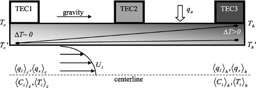
There is no direct way of controlling the temperature gradient of the wet inner walls that are responsible for generating supersaturation. Instead, the thermoelectric coolers control the temperature at the outer walls of the chamber. However, there is a temperature drop through the walls of the CFSTGC due to the continuous removal of heat at the inner wall by forced convection and evaporation, and due to the thermal resistance of the materials through which the heat must travel. As a result, the temperature gradient developed in the inner wall is smaller than applied by the TECs. If this temperature drop is not accounted for, the instrument supersaturation may be overestimated. The magnitude of this temperature drop depends on the instrument operating conditions. For instance, a higher flow rate leads to greater forced convection at the inner wall surface, and thus a greater temperature drop through the walls of the column. A procedure for estimating this temperature drop is outlined in Section 4.
3. INSTRUMENT AND DROPLET GROWTH MODELS
The CFSTGC instrument model (CitationRoberts and Nenes 2005) numerically solves the equations that govern heat, mass and momentum transfer throughout the flow chamber. The model computes temperature, velocity and water vapor concentration profiles in the column. Inputs to the model are total volumetric flow rate (Q), sheath-to-aerosol flow ratio (SAR), pressure (P), and the inner wall streamwise temperature difference (Δ T inner) between the exit and entrance (T h ′ and T c ′, respectively) of the column. For all atmospherically relevant measurements, the impacts of CCN growth on the gas phase water vapor and heat balance are negligible (CitationNenes et al. 2001; CitationRoberts and Nenes 2005). Thus, the simulated supersaturation, velocity, and temperature profiles are used to compute the growth and activation of CCN as they flow through the chamber (with a user-defined size distribution and composition). Integration of the droplet growth equations is accomplished by the LSODE (Livermore Solver for ODEs) solver (CitationHindmarsh 1983). For more details refer to CitationRoberts and Nenes (2005).
To analyze the CFSTGC, we vary Δ T inner, Q, and P over their operational range and simulate the instrument performance for the combinations of these parameters given in . The maximum Δ T inner and minimum Q are set to limit secondary flows developed by thermal buoyancy. The minimum Δ T inner and maximum Q are limited by the detectability of activated droplets and by the desire for establishing developed flow fields in the flow chamber, respectively. For all simulations considered, the temperature of the air (both sheath and aerosol flows) entering the column is 293 K, the SAR is 10 and the liquid water flow rate is 4 mL hr− 1 (which corresponds to the “low” default setting in the instrument control software). The flow field is discretized into 100 grid points in the streamwise direction and 100 grid points in the radial direction.
TABLE 1 Input variables to the CFSTGC instrument model: pressure (P, atm), inner wall streamwise temperature difference (Δ T inner, K) and total volumetric flow-rate (Q, L min− 1)
For the simulations in this study, we consider CCN described by a single, broad lognormal mode of ammonium sulfate aerosol with a mean dry diameter of 0.07 μ m, geometric dispersion of 2.0, and number concentration of 60 cm− 3. The water vapor condensation coefficient, α c , is assumed to be 0.042 (CitationFeingold and Chuang 2002). An additional simulation is run with α c = 0.005 (CitationChuang 2003), to explore the instrument response to slowly growing CCN. Simulations with α c > 0.042 are not considered, as the instrument performance would always improve.
4. CHARACTERIZATION OF WALL THERMAL RESISTANCE
4.1 Definition of Thermal Efficiency
Supersaturation strongly depends on the inner wall streamwise temperature difference (Δ T inner = T h ′ − T c ′) which may be a fraction of the temperature difference imposed by the TECs at the outer wall of the column (Δ T outer = T h − T c ), where T h is the (hot) temperature at the exit and T c is the (cold) temperature at the entrance of the flow chamber (). The temperature drop across the walls is expressed in terms of a non-dimensional thermal efficiency, η, as:
FIG. 2 Cross-sectional representation of the CCN column turned on its side. The temperature drop through the wall (Δ T) increases as the flow approaches the exit of the column. Thus, the effective streamwise temperature difference applied to the air (Δ T inner = T h ′ − T c ′) is less than the outer wall streamwise temperature difference that is controlled by the Thermal Electric Coolors (TECs) (Δ T outer = T h − T c ).
4.2 Experimental Determination of Thermal Efficiency
Calibration experiments are performed to constrain the thermal efficiency of the CCN column under specific conditions. shows the experimental setup. An ammonium sulfate or sodium chloride aqueous solution is atomized (using ∼ 1.0 L min− 1 of dry filtered air), passed through a diffusional drier, diluted and then classified by a Differential Mobility Analyzer (DMA) (TSI, Inc., model 3081) with 10.0 L min− 1 recirculating sheath flow. While keeping the DMA voltage constant, the classified flow is sampled by an Ultrafine Condensation Particle Counter (UCPC) (TSI 3025A) and the CFSTGC. Over a period of 5 minutes, the concentration of total particles (or, condensation nuclei, CN) and CCN are measured, and the average activation fraction (CCN/CN) is computed. This process is repeated over many classified particle sizes, so that CCN/CN ranges from zero to unity. The resulting CCN/CN curve, or “activation curve,” exhibits a characteristic sigmoidal shape (). The instrument supersaturation is then equal to the critical supersaturation of the particle (calculated from Köhler theory) obtained from the activation curve at a 50% activated fraction.
FIG. 3 Activation curve for (NH4)2SO4 (grey dotted) and NaCl (black solid) aerosol with Δ T outer = 5.35 K, Q = 0.5 L min− 1 and P = 0.8 atm. The activation curves are used to estimate the instrument supersaturation and to calibrate the thermal resistance of the CFSTGC walls. The instrument supersaturation is determined by the inflection point of the activation curve (at 50% activated fraction). Error bars show one standard deviation in the activated fraction.
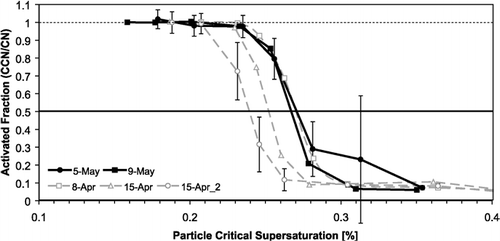
Activation curves using NaCl and (NH4)2SO4 () were generated under the following operating conditions: 5.35 K applied streamwise temperature difference, 0.5 L min− 1 total flow rate, 10 SAR and ∼ 0.8 atm pressure. To avoid coincidence counting errors in the UCPC, the total particle concentration is always less than 2000 cm− 3. A Scanning Mobility Particle Sizer (SMPS) was used briefly to validate the size of the classified aerosol particles entering the CFSTGC; the classified particle size was confirmed by the SMPS system to within 1 nm. When applying Köhler theory, thermodynamic properties are calculated at the outer wall mean temperature. The sigmoidal shape of the activation curve is marred by a second aerosol mode composed of doubly charged particles (less than 10% of the classified aerosol) that have a much lower critical supersaturation than singly charged particles of the same mobility (because the former are physically larger). Using a van't Hoff factor of 2 for NaCl and 3 for (NH4)2SO4 and a dynamic shape factor of 1.02 for NaCl and 1.0 for (NH4)2SO4 (Zelenyuk et al. in review), the instrument supersaturation for the experiments shown in is calibrated to be 0.255 ± 0.015%. Most of the variability can be attributed to the calibrations from one day, April 15.
Although the supersaturation uncertainty is small, it is important to understand its source. Variability in the atomized aerosol size distribution can account for only up to ∼ 20% of the range in the calibrated supersaturation. Measured outer wall temperature fluctuations (< 0.1°C) can only account for 1%. Additional uncertainty may be associated with changes in the liquid water drip rate. An increase in the water drip rate may remove more heat from the column walls, thereby potentially lowering the inner wall temperature and supersaturation. Furthermore, changes in the wetting efficiency will change the void fraction within the ceramic lining, which can have a notable impact on the thermal resistance.
Simulations suggest that, for the conditions of the calibration experiments, the supersaturation should be between 0.34% and 0.36% if the wall thermal resistance is neglected. To reconcile observed with simulated supersaturation, Δ T inner must be 4.1 ± 0.25 K rather than the Δ T outer of 5.35 K. Comparing Δ T outer and Δ T inner via Equation (Equation1), η is equal to 75 ± 4%.
η is expected to vary with operating conditions, however the thermal resistance is not. Thus, using the above calibration experiments to estimate the thermal resistance, we can then use the instrument model to predict the thermal efficiency over a wide range of operating conditions. Additional calibration experiments at a higher flow rate and temperature gradient will further constrain our thermal resistance calculations. A procedure for estimating the thermal resistance is described at the end of Section 4.3.
4.3 Theoretical Determination of Thermal Efficiency
A simple heat transfer model can be used to calculate the thermal resistance through the wetted walls. At steady state, conservation of energy dictates that the enthalpy increase in the gas phase (from the entrance to the exit of the column) is equal the heat applied at the outer wall (q a ), as shown in Equation (Equation2).
The latent heat from the evaporation of water from the column walls is given by,
The sensible heat, Δ q s = [⟨q s ⟩ h − ⟨ q s ⟩ c ], is calculated as follows,
Using the ideal gas law, [mdot](r,z) is given by,
The heat capacity of moist air, C pm (r,z), is calculated from the dry air heat capacity, C p (r,z), and the heat capacity of water vapor, C pw (r,z) (CitationSmith et al. 1996):
Once the sensible and latent heats are calculated, q a can be calculated via Equation (Equation2). This energy is applied to the outside of the column, travels through the aluminum walls, porous ceramic lining and liquid water film, evaporates water on the inner surface of the column and heats the gas phase. The applied energy is related to the inner wall temperature by using the equation for conductive heat transfer, which, for cylindrical coordinates, is given by CitationKreith and Bohn (1997),
Solving Equation (Equation10) in terms of the overall temperature drop through the wall (from the outer radius of the aluminum walls to the inner radius of the liquid water film),
Thus, to obtain the thermal resistance from the calibrations, we must know the mean inner and outer wall temperature and the total applied energy.
From our calibration experiments, the calculated thermal resistance ranges from 2.7 K W− 1 to 4.6 K W− 1, with an average of ∼3.7 K W− 1. These values are for a liquid water drip rate of 4 mL hr− 1 (the stated flow rate in the instrument hardware manual for the “low” peristaltic pump setting). However, due to changes in the peristaltic pump speed, the liquid water drip rate may have been higher for some of the calibrations. To estimate the effect on thermal resistance we doubled the liquid water drip rate in the calculations for those experiments. With an 8 mL hr− 1 liquid water drip rate, the range in thermal resistance becomes 2.7 K W−1 to 3.9 K W− 1, with an average of 3.3 K W− 1.
We performed additional calibration experiments with a higher flow rate and a higher temperature gradient, respectively, to verify that the thermal resistance is within this expected range. With a flow rate of 0.5 L min − 1 and a Δ T outer of 7.9 K, the thermal efficiency is 78%, resulting in a calculated thermal resistance of 3.1 K W− 1 (with 4 mL hr− 1 assumed water drip rate) and 2.9 K W− 1 (with 8 mL hr− 1 assumed drip rate). Increasing the flow rate to 0.6 L min− 1, with a Δ T outer of 5.35 K, the thermal efficiency is 71%, with a calculated thermal resistance of 3.1–3.4 K W− 1.
If indeed the decrease in instrument supersaturation is from the thermal resistance across the chamber wall, then the calibrated thermal resistance should be close to that calculated with Equation (Equation12). With a wall thickness (δ
Al
= (r
o
− r
i
)
ss
= 10 mm), porous ceramic lining thickness (δ
c
= 2.54 mm), water film thickness (δ
H
2
O
= 2.54 mm), thermal conductivity of ceramic (![]() c
= 4.2 W m− 1 K− 1 for zeramic, www.prgtech.com), thermal conductivity of water (
c
= 4.2 W m− 1 K− 1 for zeramic, www.prgtech.com), thermal conductivity of water (![]() H
2
O
= 0.6 W m− 1 K− 1) and aluminum (
H
2
O
= 0.6 W m− 1 K− 1) and aluminum (![]() Al
= 238 W m− 1 K− 1) (CitationKreith and Bohn 1997), and column inner radius and length (R = 11.5 mm and L = 0.5 m, respectively), the expected thermal resistance is R
T
= 0.2 K W− 1, tenfold less than calibrations indicate. However, the column is not quite as simple as Equation (Equation12) implies; since the walls are smooth and the ceramic is porous, there is always a “contact resistance” between the aluminum walls and the porous ceramic lining, which could be significant (CitationKreith and Bohn 1997). We approximate the effect of a contact resistance by adding a thin “air layer” in series with the ceramic (δair = 1 mm, kair = 0.0258 W m− 1K− 1 (CitationKreith and Bohn 1997)), and the expected thermal resistance increases to 1.2 K W− 1. Air bubbles, or non-uniform wetting of the ceramic throughout its whole volume would have a similar effect on the thermal resistance. Any departure from the ideal smooth contact of materials or uniform material properties is expected to increase the thermal resistance; hence, the thermal resistance calculated directly from Equation (Equation12) is expected to be a lower estimate.
Al
= 238 W m− 1 K− 1) (CitationKreith and Bohn 1997), and column inner radius and length (R = 11.5 mm and L = 0.5 m, respectively), the expected thermal resistance is R
T
= 0.2 K W− 1, tenfold less than calibrations indicate. However, the column is not quite as simple as Equation (Equation12) implies; since the walls are smooth and the ceramic is porous, there is always a “contact resistance” between the aluminum walls and the porous ceramic lining, which could be significant (CitationKreith and Bohn 1997). We approximate the effect of a contact resistance by adding a thin “air layer” in series with the ceramic (δair = 1 mm, kair = 0.0258 W m− 1K− 1 (CitationKreith and Bohn 1997)), and the expected thermal resistance increases to 1.2 K W− 1. Air bubbles, or non-uniform wetting of the ceramic throughout its whole volume would have a similar effect on the thermal resistance. Any departure from the ideal smooth contact of materials or uniform material properties is expected to increase the thermal resistance; hence, the thermal resistance calculated directly from Equation (Equation12) is expected to be a lower estimate.
4.4 Mapping Thermal Efficiency
To map the thermal efficiency over a wide range of operating conditions, we first specify Δ T inner, since this is required by the instrument model. The heat transfer model, combined with the numerical simulation of the flow field, is used to determine the total energy, q a , applied to the air and water flowing through the column (section 4.3). The thermal resistance, R T , obtained from calibration experiments (section 4.2) is used with Equation (Equation13) to determine Δ T outer, as
Both T c and T c ′ are known, as they are measured. Having calculated Δ T outer, thermal efficiency can then be calculated from Equation (Equation1).
The instrument model is run using the calibrated thermal resistance to determine thermal efficiency for all combinations of the operating conditions listed in . Although Δ T inner is needed in order to perform the heat transfer calculations, it is much more convenient to have a direct estimate of thermal efficiency as a function of Δ T outer. In order to determine this relationship explicitly, we have performed a multivariate regression of the simulations (R2 = 0.99):
To include the effect of thermal resistance, we have performed the regression of thermal efficiency (Equation Equation15) multiple times using different values of thermal resistance (1.0–5.0 K W− 1), each with an R2 > 0.99. Each value for thermal resistance produces a different set of coefficients. Then we performed polynomial regression of the coefficients with respect to thermal resistance, using the lowest order that results in an R2 > 0.995. The result is a series of 13 coefficients, many of which are in terms of thermal resistance (), which are then used in Equation (Equation15) to estimate thermal efficiency. shows the thermal efficiency as a function of Q and Δ T outer, for different values of thermal resistance, at 1 atm pressure and an inlet temperature of 293 K. The thermal efficiency ranges from 40% to 95%, and is most sensitive to Q and R T , with a weaker dependence on Δ T outer, T c ′, and P. The pressure and inlet temperature dependences are not shown in , but can be calculated via Equation (Equation15). The parameterization duplicates the full simulations to within 0.8% (absolute) of the thermal efficiency, for the given range in operating conditions.
FIG. 4 Thermal Efficiency through the walls of the CFSTGC versus total flow rate, for a given Δ T outer (indicated by color) and R T . Dotted and solid lines are to easily distinguish between different values of thermal resistance. Δ T inner can be calculated by multiplying η by Δ T outer. Pressure is 1 atm and a SAR of 10 is used.
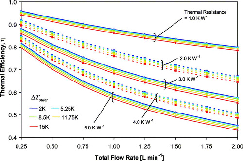
TABLE 2 Regression coefficients for Equation (Equation15). R T is the thermal resistance [K W− 1]
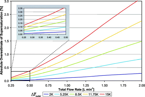
With our calibrated thermal resistance of 3.5 K W− 1, the thermal efficiency ranges from 50% to 85%, corresponding to a maximum temperature drop through the CFSTGC walls (T h − T h ′) from 0.25 K to over 7.0 K (assuming that the inner and outer wall temperatures are equal at the inlet). With a flow rate of 1 L min− 1 and Δ T outer of 11.75 K, Δ T inner is 4.0 K lower (7.75 K). Thus, for this example the maximum temperature drop through the walls (T h − T h ′) is 4.0 K, and a supersaturation of 1.4% is generated with Δ T inner = 7.75 K. Another simulation using Δ T inner = Δ T outer = 11.75 K (i.e., neglecting thermal resistance) predicts an instrument supersaturation of 2.2%, resulting in a 0.8% absolute overestimate in supersaturation. summarizes the overestimate in supersaturation that results from neglecting thermal efficiency, as a function of flow rate and Δ T outer, at 1 atm pressure, 293 K inlet temperature and with a thermal resistance of 3.5 K W− 1. The overestimate in supersaturation can be as large as 3% (absolute difference) at high flow rates and temperature gradients.
4.5 Mapping Supersaturation
We parameterize the instrument supersaturation based on the inner wall temperatures, using multivariate nonlinear regression. The scaling analysis from CitationRoberts and Nenes (2005) approximates the functional dependence of supersaturation upon the instrument operating to 335pt conditions (for fully developed flow, temperature, and concentration fields) as,
4.6 Recommended Procedure for Calibrating Thermal Resistance
It is expected that the thermal resistance will vary between instruments, and that the thermal properties of a single instrument may change over time. Since small changes in the thermal properties of the materials can have an important impact on supersaturation, a thermal resistance of 3.5 K W− 1 should not be used for all DMT CFSTGC units. Rather, the following procedure should be used to characterize the thermal resistance of a given CFSTGC unit and to estimate the unit's thermal efficiency and supersaturation.
In the absence of the instrument model, the recommended procedure for mapping out the thermal efficiency is as follows: (1) Calibrate the instrument experimentally using classified aerosol as described in Section 4.2. Infer the instrument supersaturation from the resulting activation curve. (2) Use the multivariate regression of supersaturation (Equation Equation16) as a proxy for the instrument model, to determine the Δ T inner required to reproduce the calibrated supersaturation. Use Δ T inner and the known Δ T outer to calculate thermal efficiency at the calibration operating conditions via Equation (Equation1). (3) Use the multivariate regression of thermal efficiency (Equation Equation15) to determine the thermal resistance of the instrument. (4) With the thermal resistance known, Equation (Equation15) can be used under any operating conditions to estimate the thermal efficiency and thus the true Δ T inner. Equation (Equation16) can then be used to estimate the instrument supersaturation.
5. PARTICLE GROWTH AND CCN COUNTING
CCN are counted by growing to a size large enough to be detected in the OPC. Overcounting will occur if the OPC detection threshold is within the size range of unactivated haze aerosol. Similarly, undercounting of CCN will occur if the OPC detection threshold is larger than the minimum activated droplet size. It is therefore important to determine the appropriate OPC detection threshold to avoid counting biases.
5.1 The Optimal OPC Detection Threshold
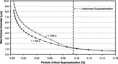
In determining the optimal OPC detection threshold, β, we employ the droplet growth model. We consider the growth of a broad lognormal aerosol distribution (as described in Section 3) through each streamline of the aerosol flow. The OPC views droplets simultaneously from all streamlines; thus, even with a perfectly monodisperse aerosol, slightly different supersaturations and residence times for each streamline broadens the droplet size distribution measured by the OPC. The simulations are expressed as “growth curves,” or in terms of the wet particle diameter at the exit of the flow chamber as a function of the particle critical supersaturation (which is related to dry particle size). shows a typical “growth curve” and visually demonstrates the criteria for a good OPC detection threshold. Particles with critical supersaturations above the instrument supersaturation do not activate, and thus remain as interstitial haze aerosol, while those that do activate grow quickly to a much larger size. β occurs at the transition between these two aerosol modes, at the inflection point of the growth curve, and thus represents the minimum droplet size at the outlet of the CCN column.
FIG. 6 Example model growth curve (wet particle diameter versus particle critical supersaturation), showing the criteria for an acceptable OPC detection threshold. Error bars show the uncertainty in particle size due to non-uniform supersaturation and residence times. Also shown is the sigmoidal curve used to fit the model results at the inflection point.
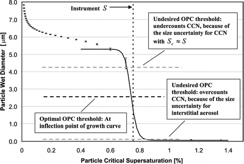
To determine the inflection point of the growth curves, the droplet growth simulations are fit to a sigmoidal function,
Figure 7 Instrument supersaturation (dotted lines) and optimal OPC detection threshold (solid lines) versus flow rate, for five different values of Δ T inner (represented by color). Error bars represent the range in outlet droplet size for the same dry particle diameter (with S c equal to the instrument supersaturation) exposed to the supersaturations and residence times of different streamlines. Color scheme same as in .
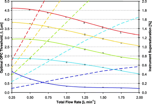
To illustrate the relationship between the outlet droplet size and the instrument operating conditions we present a simplified diffusional growth equation for activated droplets. Neglecting curvature and solute effects, the growth rate can be expressed as (CitationRoberts and Nenes 2005),
To determine τ, we first estimate the time it takes for the supersaturation to develop. The hydrodynamic (x H ), mass (x M ) and thermal entrance lengths (x T ) are given by (CitationKreith and Bohn 1997)
Figure 8 Minimum time available for droplet growth in the CCN column vs. total flow rate, for three different pressures.
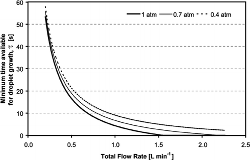
Using the scaling analysis in Equations (19–24), we parameterize the optimal OPC threshold according to the following functional form.
5.2 Resolution Ratio
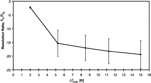
The measurement of CCN concentration in the OPC must not depend on the droplet growth kinetics; this requires that all activated CCN with S c smaller than the instrument supersaturation become distinctly larger than unactivated aerosol. In order to quantify our ability to distinguish between droplets and interstitial particles, we use a normalized “resolution ratio” as defined below (CitationNenes et al. 2001),
Although the DMT CFSTGC can generate supersaturations below 0.1%, the resolution ratio can become very small for particles with S c < 0.1%. Particles with low S c have a large unactivated equilibrium size that can be of the same order as droplets (∼1 μm), resulting in a continuous growth curve without any abrupt indication of particle activation, which makes it difficult to estimate the appropriate droplet cutoff size. Slowly growing CCN can also result in a low resolution ratio. We propose a technique for determining β for situations when the resolution ratio is small in Section 5.4.
5.3 CCN with Slow Growth Kinetics
Decreasing the condensation coefficient to 0.005 does not change the particle equilibrium vapor pressure, but it reduces the droplet growth rate. All else being equal, a lower α c means that the particles do not grow as much by the time they reach the outlet of the flow chamber. At low supersaturations, CCN with low α c may not grow to the minimum OPC detection threshold of 0.75 μm. summarizes the optimal OPC detection threshold for particles with α c of 0.005 at 1 atm pressure. It is important to note that when β is lower than 0.75 μm, CCN are undercounted. Since the instrument supersaturation does not depend on the droplet growth kinetics (for CCN concentrations of atmospheric relevance), S remains the same as the simulations using a α c of 0.042.
FIG. 10 Instrument supersaturation (dotted lines) and optimal OPC detection threshold (solid lines) versus flow rate for slow-growing particles (with α c equal to 0.005). Colors represent different values of Δ T inner. Error bars represent the range in outlet droplet size for the same dry particle diameter (with S c equal to the instrument supersaturation) exposed to the supersaturations and residence times of different streamlines. Color scheme same as in .
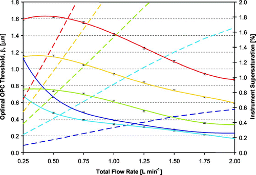
Again, we use Equation (Equation19) to understand the relationship between β and the operating conditions. As with the simulations using a 0.042 α c , β increases with temperature, as S (and thus droplet growth) increases. Although supersaturation also increases with flow rate, β decreases with increasing flow rate, as the time available for droplet growth becomes shorter. At low supersaturations, D c for CCN with S c = S increases. Although these CCN may be large enough for detection, the droplet number may be difficult to ascertain, as the equilibrium size of the unactivated particles becomes close to the size of droplets.
5.4 Distinguishing Slow Growing and Low S c Particles from Droplets
A proposed technique for distinguishing droplets from unactivated aerosol is to increase the residence time of the particles within the CCN column, while maintaining the same supersaturation. shows how doubling the residence time allows kinetically limited CCN to grow and differentiate from particles that are in equilibrium with the instrument supersaturation and do not activate. The point of divergence corresponds to the instrument supersaturation. Thus, it is not necessary to observe completely separate size modes (droplet and interstitial), in order to distinguish between activated and unactivated particles. Decreasing the total flow rate will increase the residence time, while the supersaturation can be held constant by simultaneously decreasing Δ T inner. This technique still needs further exploration, but can potentially extend the practical operating range of the CFSTGC to supersaturations significantly below 0.1%, and may also be used for observing CCN with slower growth kinetics.
6. SUMMARY
We have mapped the operation of the DMT Continuous Flow CCN Counter. First, the instrument is calibrated experimentally using atomized inorganic salt aerosol, and the instrument supersaturation is inferred from the resulting activation curves. Then we use the instrument model to determine Δ T inner from the calibrated supersaturation. Combining the model simulations and a simple heat transfer model, we determine that the thermal resistance of our CCN column is 3.4 ± 0.5 K W− 1. We also provide a multivariate regression of the calculated thermal efficiency and instrument supersaturation, to be used as a proxy for the instrument model.
Using the calibrated thermal resistance, we estimate that the thermal efficiency ranges from 50% to 85% for the range of modeled operating conditions, corresponding to a maximum temperature drop through the walls of the CCN column between 0.25 K and 7.0 K. Although pressure has a significant effect on the instrument supersaturation, it has little effect on thermal efficiency. Without taking into account the thermal efficiency, the instrument supersaturation is overestimated by up to 3% (absolute difference). We also simulate thermal efficiency for other values of thermal resistance, and provide a recommended procedure for determining thermal efficiency for specific DMT CCN units.
A droplet growth model is used to determine the optimal OPC detection threshold, which is recommended to avoid counting biases. Using an OPC detection threshold that is within the size uncertainty of the droplets may lead to underestimation of droplet counts. For most of the particles, the optimal OPC detection threshold is above 1 μ m. However, for slow growing particles (e.g., with small condensation coefficients) or for particles with very low critical supersaturations, the outlet droplet size may be smaller than the minimum OPC detection threshold.
The ability to distinguish between droplets and interstitial aerosol is quantified with a dimensionless resolution ratio; a higher resolution ratio means that droplets and interstitial aerosol are more easily distinguished. For particles with very low critical supersaturations or for slow growing particles, the resolution ratio becomes small. A technique is described for distinguishing between interstitial aerosol and droplets when the resolution ratio is small.
Exploration of the instrument response for conditions or modes of operation not considered in this study, such as when used in Scanning Mobility CCN Analysis (Medina and Nenes, JGR, in review) (i.e., in conjunction with a Differential Mobility Analyzer within scanning voltage mode) may further characterize the DMT CCN counter. However, this study provides the reader with a comprehensive set of tools and procedures to exploit most of the potential of this powerful instrument.
Acknowledgments
This work was supported by the National Oceanic and Atmospheric Administration (NOAA) under contract NA05OAR4310101 and an NSF CAREER award. SL would like to acknowledge the support of a Georgia Institute of Technology (Georgia Tech) Presidential Fellowship and a National Center for Atmospheric Research (NCAR) Advanced Study Program (ASP) Graduate Fellowship. JM acknowledges the support of a NASA Earth Systems Science (ESS) Graduate Fellowship (NGT5-30506).
REFERENCES
- Chuang , P. Y. , Nenes , A. , Smith , J. N. , Flagan , R. C. and Seinfeld , J. H. 2000 . Design of a CCN Instrument for Airborne Measurement . J. Atmos. Oceanic Technol. , 17 : 1005 – 1019 . [CSA]
- Chuang , P. Y. 2003 . Measurement of the Timescale of Hygroscopic Growth for Atmospheric Aerosols . J. Geophys. Res. , 108 Art. No. 4282[CSA]
- Feingold , G. and Chuang , P. Y. 2002 . Analysis of the Influence of Film-Forming Compounds on Droplet Growth: Implications for Cloud Microphysical Processes and Climate . J. Atmos. Sci. , 59 : 2006 – 2018 . [CROSSREF] [CSA]
- Fukuta , N. and Saxena , V. K. 1979 . A Horizontal Thermal Gradient Cloud Condensation Nucleus Spectrometer . J. Appl. Meteorol. , 18 : 1352 – 1362 . [CROSSREF] [CSA]
- Hindmarsh , A. 1983 . “ ODEPACK: A Systematized Collection of ODE Solvers ” . In Scientific Computing , Edited by: Stepleman . pp. 55 – 64 . New York : North-Holland .
- Hoppel , W. A. , Twomey , S. and Wojciechowski , T. A. 1979 . A Segmented Thermal Diffusion Chamber for Continuous Measurements of CN . J. Aerosol Sci. , 10 : 369 – 373 . [CROSSREF] [CSA]
- Hudson , J. G. 1989 . An Instantaneous CCN Spectrometer . J. Atmos. Oceanic Technol. , 6 : 1055 – 1065 . [CROSSREF] [CSA]
- Ji , Q. , Shaw , G. E. and Cantrell , W. 1998 . A New Instrument for Measuring Cloud Condensation Nuclei: Cloud Condensation Nucleus “Remover,” . J. Geophys. Res. , 103 : 28013 – 28019 . [CROSSREF] [CSA]
- Kreith , F. and Bohn , M. S. 1997 . Principles of Heat Transfer , 5th ed. , Boston : PWS Publishing Company .
- Lala , G. G. and Jiusto , J. E. 1977 . An Automatic Light Scattering CCN Counter . J. Appl. Meteorol. , 16 : 413 – 418 . [CROSSREF] [CSA]
- Medina , J. and Nenes , A. A cloud condensation Nuclei (CCN) closure on New England ambient aerosol during the ICARTT 2004 field campaign: b) effects of mixing state, JGR, in review[CSA]
- Nenes , A. , Chuang , P. , Flagan , R. C. and Seinfeld , J. H. 2001 . A Theoretical Analysis of Cloud Condensation Nucleus (CCN) Instruments . J. Geophys. Res , 106 : 3449 – 3474 . [CROSSREF] [CSA]
- Roberts , G. C. and Nenes , A. 2005 . A Continuous-Flow Streamwise Thermal-Gradient CCN Chamber for Atmospheric Measurements . Aeros. Sci. Tech. , 39 : 206 – 221 . [CROSSREF] [CSA]
- Rogers , C. and Squires , P. A New Device for Studies of Cloud Condensation Nuclei Active at Low Supersaturations . Ninth International Conference on Atmospheric Aerosols, Condensation, and Ice Nuclei . Edited by: Roddy , A. and O'Conner , T. Galway, , Ireland : Galway University Press .
- Saxena , P. and Hildemann , L. M. 1996 . Water-Soluble Organics in Atmospheric Particles: A Critical Review of the Literature and Application of Thermodynamics to Identify Candidate Compounds . J. Atm. Chem. , 24 : 57 – 109 . [CROSSREF] [CSA]
- Seinfeld , J. and Pandis , S. 1998 . Atmospheric Chemistry and Physics: From Air Pollution to Climate Change , New York : John Wiley .
- Sinnarwalla , A. M. and Alofs , D. J. 1973 . A Cloud Nucleus Counter with Long Available Growth Time . J. Appl. Meteorol. , 12 : 831 – 835 . [CROSSREF] [CSA]
- Smith , J. M. , Van Ness , H. C. and Abbott , M. M. 1996 . Introduction to Chemical Engineering Thermodynamics , 5th ed. , New York : McGraw-Hill .
- Twomey , S. 1963 . Measurements of Natural Cloud Nuclei . J. Rech. Atmos. , 1 : 101 – 105 . [CSA]
- VanReken , T. M. , Nenes , A. , Flagan , R. C. and Seinfeld , J. H. 2004 . Concept for a New Cloud Condensation Nucleus (CCN) Spectrometer . Aeros. Sci. Tech. , 38 : 639 – 654 . [CROSSREF] [CSA]
- Zelenyuk , Cai and Imre . 2005 . From Agglomerates of Spheres to Irregularly Shaped Particles: Determination of Dynamic Shape Factors from Measurements of Mobility and Vacuum Aerodynamic Diameters . Aeros. Sci. Tech. , Submitted to[CSA]
