This article describes the theoretical considerations, design criteria, and experimental performance of a cyclone-based, liquid-film, bioaerosol sampler. Different from conventional cyclones, this novel sampler draws air tangentially into the bottom of a swirling cyclone, creating a negative pressure differential which causes continuous suction of sorption liquid from its reservoir into the cyclone. The liquid swirls with the air vortex and rises spirally along the sampler wall in the form of a thin film. In the presence of an excess pressure differential, the liquid goes over the upper edge of the cyclone (overflow mode) and flows back to the bottom of the sampler. As a result, there is a continuous circulation of the sorption liquid in the sampler, which enhances the efficacy of capturing viable aerosol particles from incoming air. In this study, mathematical models using simplified Navier-Stokes equations are developed to describe the behavior of the airflow, the formation of the liquid film, and the precipitation process of the aerosol particles. Numerical solutions are presented as an approximation to these complex air and liquid flow streams in the whirlwind cyclone. Based on the theoretical assessment, practical design criteria for a novel sampler were formulated and a series of prototype samplers were fabricated and evaluated. In this report, experimental findings concerning the thickness of the air vortex, the pressure profile in the cyclone, and the apex height of the liquid film are presented. The results are in good agreement with theoretical prediction. However, the theory seems to overestimate the capturing efficiency for particles around the cutoff size (in the study, 1–2 μm) when comparing with data obtained from the experiments.
INTRODUCTION
Detection of airborne pathogenic, allergenic, and immunogenic microorganisms is crucial for developing an environmental control program that ensures a sanitary work environment. Traditionally, microbial pollution of the environment has been associated with emissions from operations in agricultural farms, poultry processing plants, landfills, and waste processing facilities. With the advent of biotechnology, new sources of bioaerosol pollution have been generated from the utilization of genetically-engineered microbial strains in producing pharmaceuticals, enzymes, and food substitutes (CitationLacey and Dutkiewicz 1994). Polluted air in this environment has been characterized by high concentrations of microbes (up to 106 colony-forming units per m3 air), including molds, E. coli, Pasteurella, Proteus, Salmonella, Staphylococcus, and Streptococcus, which are culpable for a number of infectious and allergic diseases in the human respiratory tracts (CitationOmelianets 1997). Evidence of microbial contamination in medical institutions and educational establishments has also attracted much attention (CitationLacey and Dutkiewicz 1994). These data all underlie the need for developing a comprehensive program to monitor bioaerosols in these environments.
Conventional approaches to detecting and quantifying bioaerosols often rely on sampling methods using filters, impingers, or impactors in which the microorganisms may not survive from the stress caused during the collection process. When viability is an important issue, such as in the case of microbial infection, new sampling tools are needed for adequate exposure assessment. Methods for airborne microflora collection must avoid undue physical stress on microbes and be gentle enough to sustain their physiological properties. The most promising device in this regard is liquid absorptive samplers (CitationHenningson and Ahlberg 1994), which break up airborne microbes from aerosol carriers and provide precise determination of microbes in the form of single cells. Application of a special absorptive liquid in this sampler ensures that microbial viability is sustained. Based on the task to be fulfilled at detecting airborne microorganisms, the main requirements for such a sampler are:
| • | Aspiration through the sampler of the required air volume providing control over low concentration of airborne microbes; | ||||
| • | High efficiency of capturing aerosol particles; | ||||
| • | Enrichment of captured particles into a small volume of absorptive liquid; | ||||
| • | Maximal sustainability of the captured microorganisms with the use of both gentle settling conditions and protective components as a part of absorptive liquid; and | ||||
| • | Low aerodynamic resistance of the sampler allowing use of low power electric supplies and aspiration devices. | ||||
There are many ways to capture particles in cyclone devices (CitationGreen and Lane 1964). The reported cyclone chambers have different mechanisms for flow twisting, e.g., tangential nozzle or peripheral air input by slanted blades, and different ways of air output, e.g., in the center of the chamber via flashing hole or from the chamber periphery via tangential manifold (CitationLicht 1980; CitationStark 1990). In the case of the swirling samplers the particles are deposited on a water surface, such as in scrubbers. These are widely used for purification of aerosol emissions at production enterprises, but seldom used for aerosol capturing into a sampler because of the difficulties in microbe quantification (CitationWilleke et al. 1998; CitationBirenzvige et al. 1998). In liquid aerosol samplers, a bubbling mode of air intake and liquid interaction is commonly used. However, on the surface of the thin films of the air bubbles, high shear tensions lead to considerable inactivation of the settled biological agent. This is considered the main deficiency of such type of devices. To avoid this, two considerations have been made for sustaining the viability of samples collected. First, minimal shear tensions are exerted on aerosol particles during tangential settling in the centrifugal field. Secondly, laminar motion of liquid is applied while circulating the particles in the sample. These conditions are realized in the design of a novel swirl sampling device, which is a part of the original work reported previously by CitationSigaev et al. (2002).
LIQUID-FILM SAMPLER
The swirling cyclone-type sampler considered in this paper with recirculating liquid film is a modified version of the sampler invented by CitationOlenin et al. (1977). It is based on a known principle of producing a rotating liquid film on the inner side of a settling cyclone by using the energy from aspirated outside air. shows the schematic diagram of this prototype liquid sampler (CitationSigaev et al. 2001). The inlet nozzle of the sampler is inserted into the cyclone in such a way that its long axis is tangential to the cross cyclone plane. The air vortex (swirl) twisted along the cyclone perimeter has three speed vector components: tangential, centrifugal (radial), and vertical, which taken together move the vortex in a stable spiral manner. As it will be shown below, the vortex produces a negative pressure difference in the cyclone center and in the area from the cut bottom edge of the nozzle to the cyclone bottom. Due to this difference a continuous suction of absorptive liquid is created, originating from the liquid reservoir at the bottom of the sampler via axial cyclone connecting pipe, rising along the cylinder wall; thinning in the form of a helical film; and flowing over the upper cut of the cyclone. Under specific conditions a laminar flow of the film moving along the cyclone surface and its overflow is achieved. Centrifugal forces cause aerosol particles away from the airflow to mechanically settle on the liquid-film surface. The trajectory of the moving particles is nearly tangential to the film surface, which provides a gentle mode of particle deposition into the liquid film. The continuous recirculation of the absorptive liquid in the sampler cyclone increases the accumulative particle yield in the liquid reservoir during air sampling and allows a long possible interval of taking samples. While the airflow is drawn out of the sampler through the upper coaxial with a cyclone manifold connected to a vacuum pump, the liquid reservoir will be drawn out of the sampler for microbiological analysis at the end of each sampling run.
FIG. 1 Schematic diagram of a sampler with recirculating liquid film. HC is the actual cyclone height; H is the cyclone height measured from the nozzle axis; R is the radius of the cyclone; rc is the distance between the cyclone center axis and the nozzle axis; and rB is the vortex radius.
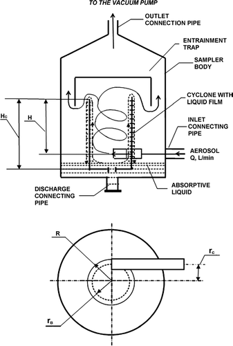
Compared to the prototype sampler used by CitationSigaev et al. (2001), improvements have been made in the present sampler by solving the problems discovered in previous tests. When the vortex cyclone was in operation, a small spray effect resulting from disturbance of the liquid film could affect its laminar behavior at the nozzle-cyclone connection and on the cyclone upper sharp edge. This triggered the requirement of a highly polished cyclone surface during manufacturing. In addition, to avoid the sprayed liquid loss, an entrainment trap (see ) is coaxially installed above the cyclone edge where the drops deposit, enlarge, and flow down to the absorptive liquid reservoir.
The report attempts to provide mathematical description of how this vortex sampler performs. Mathematical equations are used to identify important parameters affecting the sampler performance and possible ways optimizing the design. Experiments on aerosol capturing efficiency in the sampler are carried out and the results are compared with those calculated from mathematical equations.
THEORETICAL DESCRIPTION OF THE CYCLONE: FLOW FIELD AND PARTICLE TRAJECTORY
The solution of the Navier-Stokes equations is needed to calculate the fields of air and liquid velocities in the cyclone (CitationLandau and Lifshits 1986). Considering the axial symmetry of airflow in the swirling cyclone and neglecting the items with derivatives from V r , the equations in cylindrical coordinates (ϕ, r, z) are:
where P is pressure, V is velocity, and ν and ρ are medium (air) viscosity and density. Since the air stream in a swirling cyclone and the resultant liquid film are moving similarly, Equations (Equation1–Equation3) can be considered true for both. The differences in the equations lie in different numerical values of medium viscosity and density and different threshold conditions.
Several mathematically interrelated tasks are required to describe air and liquid flows in a swirling cyclone-type sampler. A precise solution for an air or liquid flow requires setting up complicated initial and boundary conditions by considering flow turbulence, flow-to-wall friction, and complex interaction of air and water flows. It is, however, a practical and sufficient approach to start with simplified process models, in which basic parameters are defined under simple conditions. In this study simplified models are used to provide an approximate description of air vortex formation, liquid-film rise, and particle trajectory and capture in the cyclone, respectively. Theoretical analyses are performed and then compared with experimental data.
Airflow in a Swirling Cyclone
Formation of a Cavity in the Center of the Swirl Flow
Equations (Equation1–Equation3) are partial derivatives and their solutions can be obtained by the numerical method of finite differences using a computer. However, such a solution is laborious and is impractical for the analysis. By accepting some simplifying conditions it is possible to find the analytical solution of Equations (Equation1–Equation3).
If the energy loss due to the medium viscosity is negligible, Equations (Equation2) and (Equation3) can be simplified by using the Bernoulli equation or law of conservation of energy:
and the law of conservation of angular momentum:
Equations (Equation4–Equation6) are used in the cyclone theory and were resolved by CitationStepanov and Zixer (1986).
Taking the differential, Equation (Equation5) can be expressed as ![]() . By substitution, Equation (Equation6) becomes dP = − ρ V
ϕ
dV
ϕ. After integration, the balance of pressure and centrifugal force produced by air flow is given by:
. By substitution, Equation (Equation6) becomes dP = − ρ V
ϕ
dV
ϕ. After integration, the balance of pressure and centrifugal force produced by air flow is given by:
where C is an integration constant.
Using Equation (Equation5), the pressure term can be expressed as:
It follows from Equation (Equation5) that tangential velocity V ϕ, increases as radius r decreases, and from Equation (Equation7a) that there exists a certain value of radius at which static pressure P equals zero, indicating that an area with zero pressure exists inside the cyclone along its axis. This solution analysis reveals that in the center of the swirl flow a cavity is formed in which the pressure difference could either be zero or even negative with respect to the ambient. Rearranging P value in Equations (Equation7) and (Equation4), the following relationship is obtained:
which reveals that vertical velocity V z does not depend on radius and is constant.
Thickness of the Air Vortex Layer
As described above air swirl as a vortex along the cyclone wall and creates a pressure cavity in the center of the cyclone. The vortex radius at which static pressure equals zero is designated as r B [see ]. To calculate r B the following designations are taken:
The relation between A and ψ is determined by the solution of a transcendent equation solved by CitationAbramovich (1944) and it is as follows:
Results of numerical solution of this equation can be approximated with accuracy within 1% by the expression:
where the coefficient and the exponent are determined by fitting this inverse power-law relationship between A and ψ. Note that A represents a dimensionless area parameter relating the cyclone to the nozzle and ψ represents a dimensionless area parameter relating the vortex thickness (R−r B ) to the cyclone, the inverse relationship in this equation does have physical meaning as that, at a given high airflow rate, a smaller nozzle (a larger A value) results in a larger vortex with a thinner thickness (a smaller ψ value).
Comparisons among Equations (Equation9–Equation12) show that vortex radius, r B , is a function of cyclone radius, R, and nozzle cross section, S c , and that a larger R and a smaller S c would result in a thinner vortex layer with a thickness of (R−r B ). As an example, for a sampler with a round-jet nozzle of 4 mm in diameter (or a rectangular nozzle with a dimension of 2 × 6 mm) and a cyclone diameter of 20 mm, the vortex diameter is 18.5 mm, i.e., the vortex layer thickness is only about 0.75 mm. This numerical assessment suggests that the vortex layer is thin and vortex radius makes up approximately 90–95% of the cyclone radius. It should be noted, however, that the assessment is only an estimation based on simplified assumptions and does not take into account that this thickness could vary with cyclone height and nozzle shape.
Estimation of the Maximum Pressure on the Wall of the Swirling Cyclone
If the air viscosity is not taken into account, the Navier-Stokes Equations (Equation1–Equation3) will look as follows:
Considering that the solution of the first equation has an integration constant dependent on z and the solution of the second one has an integration constant dependent on r, by integrating within the vortex layer (radial direction) the complete solution can be expressed as:
The integration between r = 0 and r B is excluded because there is no vortex present and V ϕ = 0 in this region.
According to Equation (Equation5), distribution of tangential velocity in the gap between the vortex boundary and cyclone wall is inversely proportional to the radius:
However, taking into account that the thickness is small and the r value used within the region of integration is practically equal to cyclone radius, the tangential velocity inside the gap can be considered constant.
By assuming that the energy loss due to the medium viscosity is negligible, the solution of Equations (Equation4–Equation6) shows that the vertical velocity in the gap between the vortex boundary and the cyclone wall is constant and equal to:
where Q is the total airflow rate (air consumption) and is equal to V 0 S c (see ).
By taking into account Equations (Equation16) and (Equation17), Equation (Equation15) for airflow pressure on the swirling cyclone wall is integrated and expressed as:
Note that Equation (Equation18) is obtained under an ideal situation without considering the energy loss due to the viscous medium and results in the maximal pressure (P max) on the wall of the swirling cyclone. This pressure is a function of the airflow rate and geometric sizes of the cyclone and the nozzle. However, in a real-life situation with viscous air and liquid, it is evident that airflow velocity decreases as it moves upward in the cyclone and values of a constant vertical speed and a maximum pressure are only applied at the near-bottom area of the swirling cyclone near the nozzle outlet. In this area the airflow pressure is equal to the hydrostatic pressure of the liquid column of water film, and vice versa, in the presence of liquid film along the cyclone wall, liquid-film elevation (H B ) equals airflow pressure (P max) in millimeters of water column. H B is an important parameter in sampler design because it provides information on the maximum height the vortex-created liquid film could reach along the cyclone wall. In reality, a cyclone of a height close to H B would be fabricated to achieve a stable laminar liquid flowing over the cyclone top so that recirculation of liquid between the reservoir and the cyclone chamber could take place prior to sample analysis. Note that if the cyclone height is higher than H B then the liquid film would not flow over the cyclone and recirculation would not occur properly. Considering that the design intent of a swirling sampler is to provide a continuous liquid film for capturing biological agents in the air for subsequent analysis, it is therefore our intention to operate liquid in an overflow mode.
Airflow Field and Particle Trajectory in a Swirling Cyclone
Based on that described above, a maximal height of the liquid rise can be estimated by using Equation (Equation18) with a uniform pressure in mm water. Further reasoning is based on the following assumptions:
| 1. | Static pressure on the cyclone wall decreases linearly with respect to the height; | ||||
| 2. | Tangential airflow velocity amounts to zero when the height is more than the maximal point of liquid-film rise; and | ||||
| 3. | The thickness of the air vortex layer remains the same through the cyclone height and equals the initial value. | ||||
To make expressions meaningful and easy to relate, the position where the central point of the nozzle resides is considered as the starting point (vertically) in the cyclone and thus designated as z = 0 in the cyclone. Considering the first model assumption, static pressure to the swirling cyclone wall equals:
where z is the vertical distance from the nozzle and H B is the maximal point of liquid-film rising from z = 0, calculated by Equation (Equation18). This designation of z is important and will be discussed later in this section.
The relationship between P
0 and initial air tangential speed V ϕ (0) could be approximately correlated as ![]() , in which pressure and velocity are in quadratic interdependence. Considering Equation (Equation19), the tangential velocity is expressed as:
, in which pressure and velocity are in quadratic interdependence. Considering Equation (Equation19), the tangential velocity is expressed as:
where Vφ (0) is the initial air tangential velocity at the central point of the nozzle location (z = 0).
Equation (Equation20) is true for the region where positive pressure P(z) exists, i.e. within the vortex. For the region with a zero or negative value of P(z) air tangential velocity equals zero.
Similarly, on the assumption of the Bernoulli equation (Equation [Equation4]) and Equation (Equation20) the vertical velocity is expressed as follows:
It should be noted that the location of z = 0 is not vertically situated at the same level as the bottom of the cyclone, but rather, it is higher than the bottom by a given distance (= H C −H; see ). This relation is important when discussing z-value with respect to parameters such as the cyclone height, H, or the maximal height of rising liquid film, H B . Although H C is the actual cyclone height in fabrication, H and H B are mainly used in the equations for mathematical simulation. In an actual cyclone, the region between the nozzle exit and cyclone bottom is crucial for forming a stable circulating liquid film. If this distance is too long, neither liquid suction nor liquid-film formation process would take place. On the other hand, as the distance is too short, the liquid film formed would be too thick and unstable. Preliminary results from some prototype designs indicate that this distance, H C −H, should not be more than 5–10 mm so that an unstable liquid film resulting from air turbulization of the near-bottom liquid layer can be avoided, especially under high air velocities at input flow rates of 60–80 l/min.
Airflow Trajectory in the Swirling Cyclone
To calculate the spatial trajectory of the airflow the expression for tangential velocity can be represented as:
where ϕ is the angle in radians.
Integrating the equation results in:
Using the relationship of dt = dz/V z (z), the variable is changed and the expression becomes:
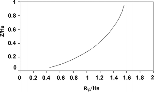
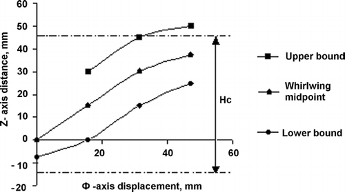
The diagram of airflow lines calculated by Equation (Equation23) is given in .
Since the term Rϕ represents the spatial displacement of spiral airflow along the wall surface, the curve in relates the spiral distance to a given height (in units of H B ) and thus reveals the airflow trajectory. Because V z increases, but V ϕ, decreases with z (Equations [Equation20] and [Equation21]), the slope of airflow trajectory increases with z and the angle of inclination is approximately 45° when z = 0.5H B . Assuming that the cyclone height H is equal to the liquid rise H B , the number of airflow revolutions in the swirling cyclone can be determined by substituting ϕ = 2πN and z/H B = 1 in Equation (Equation23):
where T is the time needed for the airflow to reach the maximal rising point of liquid film. This expression indicates that the number of revolutions in the cyclone is determined only by the geometrical dimensions of the swirling cyclone and does not depend on the geometrical dimensions of the nozzle. In addition, it shows that the airflow trajectory is about one revolution when the cyclone height is approximately twice of cyclone diameter. In this study the ratio of H B /R has kept ∼4–6 as one of the criteria in designing and fabricating compact samplers and, as a result, N is approximately one revolution.
Aerodynamic Resistance of Particles and Particle Capturing Efficiency
With the above description on the formation of the cavity and derivation of air vortex, pressure diagram, and airflow trajectory in a swirling cyclone, we now focus on the aerodynamic behavior of the particles entrained in the airflow of the cyclone. The inertial properties of aerosol particles moving in vortex air stream can be assessed with an initial condition that the particle tangential velocity at the nozzle section is equal to the air velocity and the velocities in radial and vertical directions equal to zero.
Particle Radial Velocity
According to CitationHinds (1999), aerosol particles moving in a curvilinear air flow are influenced mainly by two forces: centrifugal force and aerodynamic resistance (Stokes drag force). For a small particle, gravity can be neglected and aerodynamic resistance, F, depends on particle velocity and surface area:
where C D is the drag coefficient, ρ is the air density, and S p and V p are the cross-sectional area and the velocity of the particle. The aerodynamic coefficient depends on particle Reynolds number, Re p = ρVpdp/μ, where d p is the particle diameter and μ is the air viscosity. For Re p < 1, C D = 24/Re. Assuming a particle has spherical shape and laminar movement in radial direction the following equation can be expressed in cylindrical coordinates:
where m is the particle mass, V p ,r is the particle radial velocity, and V ϕ is the air tangential velocity. The cyclone radius, R, is used for the centrifugal force calculation because the trajectory of initial particle flow in a cyclone is determined by the whirlwind trajectory at r B , the vortex radius, which makes up 90–95% of cyclone radius, R, described above.
The solution of the simple differential equation for radial velocity of particles V p , r is:
where ρ p is the particle density and τ is the particle relaxation time (= m/3πμdp).
The stationary solution of the equation is:
The relaxation time for aerosol particles is small and at t = 3τ particle velocity in a whirlwind is practically equal to its stationary value (CitationHinds 1999). Thus, the stationary value of particle radial velocity (according to Equation [Equation26]) could be used to a high accuracy for particle precipitation calculation.
Particle Capturing Efficiency
To calculate the particle capturing efficiency in the liquid film the following assumptions are made:
| 1. | At t = 0 particles are uniformally distributed through the section between the vortex radius and cyclone wall; | ||||
| 2. | Air flow is laminar; | ||||
| 3. | Particle velocities by ϕ and z axes are equal to corresponding constituents of airflow velocity according to Equations (Equation20) and (Equation21). Particle velocity by r axis is determined by centripetal force impact on a particle and calculated by Equation (Equation26). | ||||
| 4. | Once the particles are in the liquid film they are considered captured. | ||||
Capturing efficiency, η, can be determined by:
where t p is the time of particle staying in the cyclone. Taking into account that tangential velocity of air (particle) depends on z[V p , r (t) = V p , r (z) and dz = V z (z) dt], capturing efficiency can be determined by the following expression:
where V p , r , st (z) and V z (z) are expressed in Equations (Equation26) and (Equation21), respectively.
Dependence of tangential velocity V ϕ, on z in Equation (Equation26) is calculated by Equation (Equation20). Since the height of the swirling cyclone, H, is equal to or slightly less than the maximal point of rising liquid-film, H B , the integral with analytical expressions for radial and tangential velocity amount to:
where B = ![]() .
.
Substituting the relation of ψ and r B /R (Equation [Equation10]) and the equality of V ϕ(0) = V 0 = Q/Sc into Equation (Equation27a), the expression of η (η < 1) becomes:
Taking into account that (1 − (1 − ψ)1/2) can be closely approximated by using analytical expression similar to that shown in Equation (Equation12), it is related to A as follows:
where the coefficient and the exponent in this inverse power-law relationship are obtained by fitting the inverse power-law relationship between A and 1 − (1 − ψ)1/2. The final formula for capturing efficiency is
where μ, Q—air viscosity and flow rate, d p , ρ p —particle diameter and density, R—radius of the swirling cyclone, H B —maximum liquid rising height, r c —radius of the nozzle location, and S c —cross-sectional area of the nozzle. To maximize the particle capturing efficiency of the swirling sampler, the maximal point of the liquid-film rise, H B , is normally close to the height of the cyclone, H (∼ H B) [see ]. Thus, analytical expression connecting capturing efficiency of particles in the swirling cyclone and its geometrical dimensions is obtained and the efficiency is proportional to d p 2, Q, and H B , and inversely proportional to R 2. Because it is assumed that once the particles are drawn into the liquid they are captured, no properties associated with the liquid (e.g., density, viscosity, and surface tension) are shown in the equation.
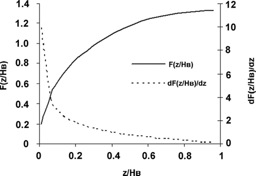
Besides the total particle capturing efficiency, it is also important to have the information on the amount of particles captured in different parts of the swirling cyclone. Without considering the integration in Equation (Equation28), the capturing efficiency on coordinate z is determined by the following expression:
where F(z/H B ) is a simplified function of z/H B ; B is a constant related to the properties of the particle and the medium defined in Equation (Equation28); and (R−r B ) is the vortex layer thickness. The analytical expression for particle settling density in the zdirection is expressed as follows:
Differential dependence of capturing efficiency on z is proportional to the derivative of F(z/H B ) function. Diagrams of these functions are given in . Differential dependence shows that the major part of aerosol particles are captured in the first part of the swirling cyclone independent of particle size and airflow parameters.
Considering that the height of the swirling cyclone H is close to H B , in practice H can be used in the above expressions.
Calculation of Particle Capturing
Total Particle Capturing Efficiency
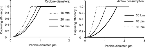
Capturing efficiency of particles in a swirling cyclone is determined using Equation (Equation30). Given a fixed H = 50 mm and different combinations of air flow rate, Q, and cyclone diameter, 2R, capturing efficiencies of particles at various sizes are shown in and , which illustrate curves with a general trend of exponential increase with respect to particle size followed by a plateau. The results show that particles > 2 μm are 100% captured independent of swirling cyclone dimensions and airflow rate, while the efficiency of capturing particles < 2 μm depends on both the cyclone dimensions and flow rate. These are expected since, at a higher flow rate (in (b) with a fixed cyclone diameter) or a smaller cyclone diameter (in (a) with a fixed flow rate), the cyclone would operate at a higher velocity and, consequently, the particles would possess a higher inertia in the swirling chamber and result in ahigher capturing efficiency in the cyclone.
Particle Capturing Efficiency at Different Height of the Swirling Cyclone
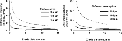
Using Equations (Equation31) and (Equation32) the particle capturing efficiency can also be determined at different heights, z, of the swirling cyclone. and show calculated results for monodisperse aerosols at certain airflow rates and particle sizes. The curves illustrate a general trend similar to that of dF/dz in . The differential efficiency data, in relative values, indicate that particles are mainly captured in the region of the nozzle exit. That is expected since the air velocity and the corresponding centrifugal force are maximal near the nozzle opening at the bottom of the cyclone.
EXPERIMENTAL RESULTS AND DISCUSSION
Experimental Installation
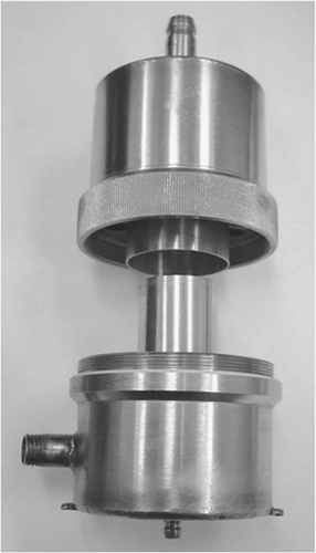
Based on the information from the theoretical predictions and practical considerations described above, prototype sampler used by Sigaev and his coworkers (Citation2001 and Citation2002) is shown in with a schematic similar to that shown in .
illustrates the experimental setup used for investigating the airflow pressure profile, the liquid-film formation, and the particle capturing efficiency in cyclones. The sampler in this setup is different from that shown in as that the upper part of the sampler body and the entrainment trap were excluded. In addition, the liquid was supplied through a pipe connected to an external reservoir rather than from a liquid reservoir inside the sampler body as shown in . In this setup different devices were installed for different experiments, e.g., micromanometers for pressure measurements and paper slides for visualizing the traces of particle deposition profiles, respectively.
FIG. 7 (a) Schematic diagram of the setup for different experiments; (b) Top-view of points for pressure measurements using a mobile sonde connected to mP1.
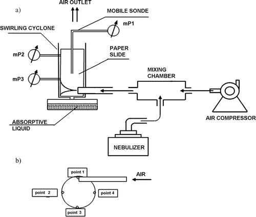
To maintain a consistent parametric study throughout the experiments a set of base values for the sampler was selected as 2R = 20 mm, H C = 55 mm, Q = 60 l/min with a rectangular-jet nozzle dimension of 2 × 6 mm or round-jet nozzle of 4-mm in diameter. To provide a sufficient airflow through the sampler, the inlet nozzle was connected to a mixing chamber where aerosol generated from a nebulizer was diluted with clean air from an air compressor. Such a combination of two airflows was needed because the flow rate from the Collison nebulizer (MRE CN24/25, BGI Inc., USA) was only 8–15 l/min, which required an air compressor to supply diluting air to make up a total airflow of 30–80 l/min under the demand of a vacuum pump, attached to outlet nipple of the sampler.
Airflow Pressure Profile in the Cyclone
A prototype sampler fabricated according to the base values was used to examine the pressure profile in the cyclone. The cyclone height and diameter were 60 mm and 20 mm, respectively, and the inlet nozzle was either a rectangular (2 × 6 mm) or a circular (4 mm) jet which was tangentially introduced into the cyclone with a distance of 15 mm from the cyclone bottom. As the cyclone is rather small, quantitative measurements of whirlwind parameters, i.e., pressure and velocity, at specific locations of the cyclone could have considerable distortion. To resolve this, thin-walled brass or glass tube probes of 0.8-mm diameters were used. To be specific, a movable probe (connected to mP1) was used in one experiment and two stationary probes (for mP2 and mP3) sealed into cyclone wall at different heights were used in the other experiment. Transmitted by means of the probe, air pressure inside the cyclone was measured using micromanometers mP1, mP2, or mP3 (MMA-3 model, “Uralelectropribor,” Yekaterinburg, Russia). Whirlwind parameters in the cyclone were studied either with or without liquid film. When liquid film was needed, the cyclone bottom was connected to an external reservoir with absorptive liquid containing distilled water and 5–10% glycerin. Use of glycerin decreases considerably evaporation of absorptive liquid while it's recirculating in the device.
Airflow impact pressure profile was determined using the mobile sonde connected to mP1. The sonde was placed in the swirling cyclone parallel to the wall and its location was varied at various heights and radiuses. No liquid was used. presents data of airflow pressure evaluation with mobile sonde along cyclone wall from its upper cut to inlet nozzle axis for 45 mm depth. The sonde was moved in 4 sites along the perimeter of cyclone as shown in and the measurements in cyclone crosscuts 1–3 and 2–4 at different heights are presented in .
TABLE 1 Pressure evaluation with mobile sonde near swirling cyclone wall
TABLE 2 Pressure evaluation on 1–3 and 2–4 profiles depending on sonde distance from cyclone wall
Pressure readings taken near the swirling cyclone wall depend on the measuring position with respect to the nozzle (i.e., z-value). Data from and point out that most of the area inside the cyclone has a negative pressure relative to the ambient. In addition, data in suggest that, as the air flow exits from the nozzle at point 1, swirling counterclockwise () and upward along the cyclone wall, there exists an air sheath of positive-pressure, which is located adjacent to the circumference of the wall. This zone originates near the bottom of the cyclone (z = 0) close to the side where point 2 is located and covers a sheath with a 2-mm width and a 10-mm height (z = 0–10 mm). As the airflow swirls upward (z = 15–25 mm), this positive-pressure sheath moves along to point 3. Then, at z = 25–35 mm, it enlarges gradually to include the area where point 4 is located and eventually, near the top of the cyclone (z = 40–45 mm), merges into the side with point 1 and its cross-sectional area becomes a ring with a thickness of 2 mm. These data suggest that the pressure diagram of airflow inside the cyclone has a characteristic of a helical profile with negative pressure in the center along the cyclone axis. Zero-pressure area shows the boundary position of air stream distributing along swirling cyclone wall, which can approximately be mapped from the data in . presents the diagram of positive pressure area along the swirling cyclone wall calculated by data. Displacement in the tangential direction along the wall was calculated by Rϕ, where R is the radius of the cyclone, and ϕ is the angle in radians (e.g., π/2 for point 2 and π for point 3). The data show that airflow is distributed along the swirling cyclone wall with an inclination angle of about 45° at z = H/2 (H ∼ H B ), which corresponds well to the calculated result by Equation (Equation23) (presented in ) even though the curve does not have the exponential feature as presented in . Nevertheless, the vortex trajectory in the cyclone makes up less than one round (i.e., at z = H, L < 2 π R), which is confirmed by calculations in Equation (Equation24).
Note that the pressure measurements listed here are limited by the size (i.e., 0.8 mm) of the sonde used in the study. According to Equations (Equation10–Equation12), for a cyclone with a nozzle diameter of 4 mm (assuming a round-jet nozzle) and a body diameter of 20 mm, the vortex diameter is 18.5 mm and the calculated air vortex layer thickness is only 0.75 mm. Because the size of the moving sonde is 0.8 mm, i.e., more than the vortex thickness, pressure reading presented in and may not be suitable to use for vortex parameters calculation on the basis of earlier obtained expressions for mathematical models. As an example, at the cyclone top (z = 45 mm), data in show that positive pressure area characterizing vortex is less than 2 mm wide at every observation point 1–4. This indicates that r B /R is approximately 0.8, different from the value of 0.9–0.95 based on the numerical assessment described above in Equation (Equation12). This discrepancy could be partly because of a big sonde size as well as modifications required in the theoretical equation. Based on the data from and , the vortex has a helical characteristic and its thickness (R−r B ) is not a constant as assumed in the equation and, in fact, varies with the height z. Nevertheless, theoretical predications provide an understanding of the potential mechanisms involved and guidance to the design parameters required for a desired sampler.
Airflow Static Pressure and Tangential Velocity Measurements on the Cyclone Wall
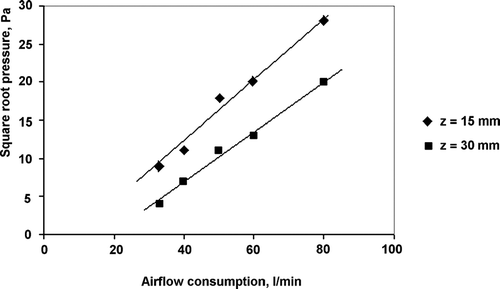
Besides mapping the pressure profile inside the cyclone, static pressure was measured using two micromanometers mP2 and mP3, shown in a. As described before, two manifolds, each with a 0.8-mm diameter, were soldered-in at two heights (z = 15 mm and 30 mm) transverse to the wall of the swirling cyclone. uses the same data to relate the square root of static pressure to the corresponding flow rate in the cyclone. The linear correlation agrees well with the expression of P∞ Q 2 in Equation (Equation18). In addition, the figure shows that, at a given flow rate, the static pressure at z = 15 mm is higher than the pressure at z = 30 mm, indicating that static pressure, as well as tangential velocity, decreases with increasing height on the cyclone wall (Equations [Equation19] and [Equation20]).
Height of Liquid-Film Rise in the Cyclone
The stable formation and optimal rising of the liquid film in the swirling cyclone are essential prior to investigation of particle capturing in the sampler. Experiments were conducted with liquid (distille The stable formation and optimal rising of the liquid film in the swirling cyclone are essential prior to investigation of particle capturing in the sampler. Experiments were conducted with liquid (distilled water containing 5–10% glycerin) to establish stable recirculation of the liquid film and then determine the maximal height of the rising liquid film at different flow rates. For the first part of the study, airflow was introduced through the cyclone to create the air vortex and liquid film. Different flow rates were examined to identify a range of flow rates that provide stable films. For identification purposes, the airflow was controlled so that the liquid film could reach as high as possible but was confined in the swirling cyclone without flowing over the cyclone top. Cyclones of a fixed height (H C = 55 mm), a fixed nozzle diameter (= 4 mm), and various sizes of cyclone diameters (= 16–24 mm) were used. presents the range of flow rates that provided stable liquid film for each cyclone. By substituting mean flow rates and cyclone dimensions into Equation (Equation18), the maximal heights of liquid-film rise (in mm H2O) at different flow rates were calculated and compared with the physical height of the cyclone, namely 55 mm. Results in indicate that the experimental data agree well with theoretical predictions especially for cyclones of 20–24 mm diameters and operated at a flow rate around 50 l/min. The results suggest that, for the cyclones tested, the critical flow rate to establish a stable liquid film and its maximal height seem to relate to the cyclone diameter. For a cyclone with a diameter of 20–24 mm, a flow rate around 50 l/min result in a stable film at a height of ∼55 mm around the cyclone top, meaning that the liquid film could overflow and recirculation would take place. However, for a cyclone with a smaller diameter, its stable film would only occur at a lower flow rate with a larger maximal liquid-film height as compared to the calculations. It could be caused by the fact that centrifugal forces created by circulating liquid film were not considered for calculations, which needs individual research. Generally, the results obtained with use of suggested simple model for liquid-film height calculation are close to experimental data and indicates that some relationship may exist among the cyclone diameter, height, and flow rate to formulate optimal dimensions for samplers with stable swirling operations. This information is important when considering an improvement of the cyclone design.
TABLE 3 Maximal water-film heights for cyclones of various design and operating parameters. Both the cyclone height and the maximal height of the water film were distances from the bottom of the cyclone
The second part of the study was to conduct experiments so that maximal heights of liquid-film rise could be quantitatively measured. Based on the information obtained above, a cyclone with a diameter of 20 mm, a height of 55 mm, and a nozzle of 2 × 6 mm was selected (the advantage of using a thin-plate nozzle is described below). The experimental setup for this study is similar to that shown in a with the bottom of the cyclone placed in a water reservoir except that the micromanometers were detached and there was no paper slide. Manifolds with a diameter of 0.8 mm were soldered-in to the cyclone at two heights (z = 15 and 30 mm), with which thin transparent tubes were connected. The other ends of the tubes were fixed much higher than the cyclone body. When air was drawn through the cyclone, liquid vortex was created along the wall and a little amount of liquid was flowing into the transparent tubes. The height of the liquid rise corresponds to the static pressure of liquid on the cyclone wall, which, in turn, is equal to the airflow static pressure on the liquid-film regardless of the manifold's location. This means the maximal pressure (or maximal height of liquid film) can be experimentally determined by summing up the height of the sonde position (z-value) and the height of liquid-column in the tube connected to the sonde. This applies to conditions under which no liquid can flow over the cyclone top. In a situation when overflow does occur, the maximal height of liquid rise would be close to but slightly higher than the height of the cyclone. shows experimental measurements of liquid-film rise and their comparisons with theoretical predictions calculated from Equation (Equation18) under the conditions with and without liquid overflow. At 40 l/min the measurements of liquid rise depend on the sonde position with a better agreement occurring at a higher position. As the flow rate increases to 50 l/min, the measurements do not depend on the sonde position and are lower than the predicted value by about 3 mm. Considering the assumptions made in the equations and limitation used in the liquid measurements, these are good agreements and imply that it is a good model to use for predicting rising liquid height. also presents a liquid overflow case when the flow rate was operated at 60 l/min. Although the maximal liquid-film rise is predicted to be about 73 mm, the measurement was only 55 mm, slightly above the height of the cyclone.
TABLE 4 Comparison of maximal liquid-film heights between measurements using soldered-in sonde tubes and predictions calculated from Equation (Equation18). Swirling cyclone has the dimension of diameter 20 mm, height 55 mm, nozzle 2 × 6 mm
Experimental Study of Particle Settling in Different Swirling Cyclones by Visualization Method
Having examined the airflow pressure profile and liquid-film formation in the cyclone, the focus was then shifted to investigate the behavior of aerosol particles in the sampler. A special technique was developed for qualitatively studying the spatial particle trajectory in a cyclone by visualizing the imprint showing the deposit of fluorescence-tagged particles. For this, color-stained particles were used, no liquid was applied, and a precut sheet of finely porous paper was pressed to the wall of the dry cyclone throughout its height and perimeter except for the area around the input nozzle. Considering that, in the swirling sampler, aerosol particles would be settled and submerged into the liquid as they touched the liquid film on the cyclone wall, the produced imprint on the paper slide would show qualitative spatial distribution of particle deposits even without liquid film. The experimental scheme is presented in without the three micromanometers and the liquid reservoir. A Collison nebulizer containing 10% aqueous glycerol solution with 2% methylene blue stain was used for aerosol generation. Once the aerosol generator started, a clear imprint was observed on the paper showing the form of the air stream in the cyclone and the resultant particle deposit on different parts of the cyclone.
Although prototype samplers of various dimensions and flow rates were used, general profiles of the imprints look similar qualitatively. and present two typical imprints showing particle traces from two different nozzles. Although the results are only qualitative, the deposition pattern in seems to illustrate a more developed thin air-sheath than that in . This indicates that while the rectangular nozzle (2 × 6 mm) delivered a developed air sheath, the round nozzle (4 mm) yielded a gradually developed point stream, suggesting that the former could provide a more stable particle-entrained air stream.
FIG. 10 The imprint of stained particles settling in the swirling cyclone using a rectangular nozzle. Note that the cut around the nozzle causes the missing sections in the imprints. (Cyclone diameter is 20 mm, height is 55 mm, nozzle dimension is 2 × 6 mm. Air consumption is 80 l/min.).
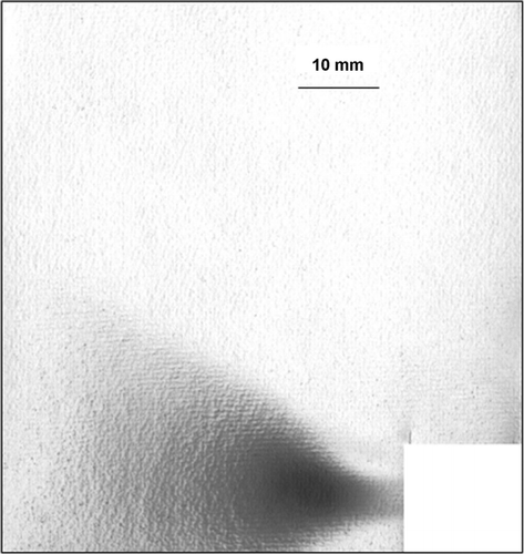
FIG. 11 The imprint of stained particles settling in the swirling cyclone using a circular nozzle. Note that the cut around the nozzle causes the missing sections in the imprints. (Cyclone diameter is 20 mm, cyclone height is 55 mm, nozzle diameter is 4 mm, and air consumption is 80 l/min.).
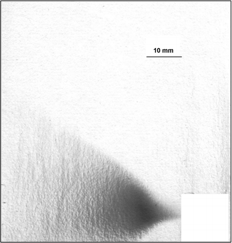
Neither figure reveals a spiral deposit as that when discussing the airflow pressure in the cyclone. Rather, both imprints show a form of a cone-shape deposit originating from the nozzle exit with a big dark spot located opposite to the nozzle. Since polydisperse aerosols were used in the experiments, the dark spot could be the deposit of large methylene blue-tagged glycerol particles as a result of impaction, in concurrence with the high fractional deposition efficiency shown in . Small particles followed the vortex and then deposited by proportionally scattering to the sector boundary. The angle of inclination of the imprint sector is about 45 degrees, which provides similar analysis to that in . Based on this, the most effective precipitation region for particles in the cyclone may be located within an area where cyclone height equals to the diameter. This is different from the theoretical analysis predicted from Equation (Equation23) since the trace of airflow stream would have an exponential increase with the height z. However, to provide a high particle capturing efficiency, it is reasonable to have a cyclone whose height (H) is greater than its diameter (2R). By reviewing the assessment on liquid-film rise (previous section), cyclones having a ratio of H/2R between 2.3–2.8 seem to yield stable liquid films. This would coincide well with the discussion on Equation (Equation24), in which H/R has kept to be ∼4–6 as one of the design criteria.
Experimental Results of Aerosol Particles Collected in Swirling Samplers with Recirculating Water Film
Research was carried out to study the capturing efficiencies of monodisperse fluorescent latex microspheres (Duke Scientific Corporation, Palo Alto, CA) in the swirling sampler. The microspheres have a density of 1.05 g/cm3 and nominal diameters of 0.5, 1.0, 2.2, and 3.0 μ m, respectively. The overall dimensions of the sampler body are 115 mm in height and 64 mm in diameter. The cyclone has a diameter of 20 mm and a height of 55 mm. The tangential inlet is in the form of a 2 × 6 mm planar slot. The flow rate used was 60 l/min. The capturing efficiency was evaluated as the ratio of microspheres captured in the sampler to total microspheres in the device and on the backup filter in its outlet nipple. The amount of microspheres in each sample was indirectly determined by analyzing the fluorescence intensity of the sample using a spectrophotometer (SF-56A, LOMO, St. Petersburg, Russia). The methods are described in detail in CitationFeather and Chen (2003) and CitationChen et al. (2004). Different flow rates were used in the study and only the data obtained at 60 l/min are presented here for comparison purposes.
By plotting in the experimental data of the capturing efficiencies it is clear that this sampler does not have a very sharp cutoff characteristics and its 50% cutoff size is about 1 μ m, different from the cutoff size of 0.5 μ m predicted from the theory. In addition, there exists discrepancy between the empirical data and the theoretical curve (Equation [Equation30]) around the particle separation zone (0.5–2 μ m). Nevertheless, the associations of capturing efficiency and particle size seem to follow the similar trend for both data sets. The possible reasons for the discrepancy could be partly due to simplification of the basic mathematical expressions describing airflow in cyclone and partly resulted from assumptions that all aerosol particles at the nozzle exit possess the same trajectory and are completely captured once they are in the liquid. Although simplified Navier-Stokes equations allow for airflow description in cyclone without considering the interaction of liquid-film swirling stream with cyclone wall and moving swirling airflow, the tradeoff is the discrepancy caused by neither setting complicated initial and boundary conditions, nor considering flow turbulence, flow wall friction and complex interaction of air and water flows. In practice, the radius R used in the calculation could have been smaller depending on the thickness of liquid film. Although there is no mathematical analysis on the thickness, experimental observation shows that the thickness varies along the height (0.8–1.0) mm up to z = 0.5H and reduce to (0.5–0.8) mm at the top, z = H). By taking into account the film thickness it would somewhat diminish the discrepancy in the efficiency. In addition, the air stream in the cyclone as observed in the visualization study was not as steep as that shown based on the model and thus the particles moving along the air stream could have followed the streamlines and not been deposited in the liquid film. As the air stream in the cyclone makes no more than one revolution, some aerosol carry-over could occur especially from the jet border zone. Furthermore, besides the factors mentioned above, particles captured in the liquid film and then in the liquid reservoir were found to be trapped and attached to the surface of the sampler body and never be analyzed. This amount could vary between 5 and 25% of the total depending on the size of the particles and how the liquid was treated and delivered for analysis. This phenomenon of particle loss can be reduced by adding a small amount of surfactant in the liquid, as well as modifying the shape of the bottom plate connected to the discharge pipe.
FIG. 12 Capturing efficiencies of monodisperse latex particles in the swirling sampler. The data points were experimentally obtained and the curve was theoretically calculated using Equation (Equation30).
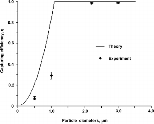
Overall, the mathematical model developed has a realistic estimate of the 50% cutoff size (approximately 0.5–1.0 μ m) and an accurate trend in terms of particle capturing. While the capturing efficiencies for particles ≥ 2 μm and ≤ 0.5 μ m are reasonably well predicted, those for particles between 0.5 and 2.0 μ m are greatly overestimated. These results indicate that the equations in Equation30–Equation32 require revisions (based on empirical data) to have better estimate on the actual capturing efficiency. Since most indoor environments have reported to have bacteria of 0.5 to 30 μ m and fungi spores of 2 to 30 μ m (CitationReponen et al. 2001), this device is suitable for bioaerosol sampling with the feature of maintaining microorganism viability.
SUMMARY
| 1. | A theoretical and experimental study of airflow peculiarities in swirling samplers was conducted. Theory predicts that, in the cyclone, there is a whirlwind vortex and its diameter makes up 90–95% of the cyclone diameter. As a result, a cavity consisting of negative or zero pressure is formed at the center of the cyclone. Within the cavity, there is zero airflow speed. With simple assumptions, the theory reveals that the whirlwind is of helical character with the number of revolutions determined by the cyclone geometry and not depending on inlet airflow parameters. Experimental results agree with predictions very well in that negative pressures were measured inside the cyclone especially along the central axis. The air vortex creates a thin, spiral layer of positive- pressure region adjacent to the walls. The layer thickness varies with the height and, at the top of the cyclone, its value is approximately 80% of the cyclone diameter. | ||||
| 2. | Equations have been formulated to predict the maximal height of liquid rising in a cyclone. For this study, experiments were specially designed to provide stable liquid films and data were obtained using measurements of static pressure of water (in mm H2O) on the cyclone walls at given heights. Results indicate that some relationship may exist among the cyclone diameter, height, and flow rate to provide an optimal set of cyclone dimensions with stable liquid-film formation. With the formation of stable films, there are very good agreements between theoretical predictions and experimental data in determining the maximal liquid-film height. | ||||
| 3. | A technique for visualization of particle settling in swirling cyclones was developed using methylene blue-tagged particles. Experimental data show that the majority of particles were settled near the nozzle. The deposition patterns, although only qualitative, seem to suggest that a rectangular nozzle provide a more stable air stream than a round nozzle. The angle of ascent of the deposited particle trace was about 45 degrees independent of cyclone dimensions and flow rate, indicating that the most effective particle capturing region could be designed with a cyclone height at least equal to the diameter. However, by reviewing the assessment on liquid-film rise, a more conservative approach was selected to have the height to diameter ratio kept to be 4–6 in the prototype design. This coincides with the theoretically proposed value and would result in about one revolution of particle trajectory in the cyclone. | ||||
| 4. | A simple mathematical model was developed to calculate the particle capturing efficiency in the liquid film along the cyclone wall. Although high efficiencies are predicted for particles greater than 1 μ m, experimental data obtained from prototype samplers exhibit lower values for particles smaller than 2 μ m. The discrepancies were partly due to the simple assumptions made in the theory, the particle-trapping hotspots that occurred in the prototype sampler design, and the methods used in sample delivery and analysis. Improvements will be made in all these categories to provide a better particle capturing characteristic in the final device. | ||||
Acknowledgments
The authors give their sincere thanks to the partners from Defense Threat Reduction Agency (DTRA), USA, for the financial and technical support and to the National Institute for Occupational Safety and Health (NIOSH), USA for the technical support of this research. This work was conducted within the framework of Partner Project #1487p under International Science and Technology Center (ISTC), Moscow. The findings and conclusions in this report are those of the authors and do not necessarily represent the views of the DTRA and NIOSH.
Notes
*Pressure readings at − were negative but not determined.
*Only the mean flow-rate value that provides stable water film was used in the calculation.
*Liquid went over the top of the cyclone (overflow mode).
REFERENCES
- Abramovich , G. N. 1944 . Theory: Centrifugal Nozzle , p. 114 Moscow : CAGI .
- Birenzvige , A. , Kiyemi , A. M. and Zaromb , S. 1998 . A Portable High-Throughput Liquid-Absorption Air Sampler for Respirable Aerosol Particles . Aerosol Sci. Technol. , 29 : 133 – 140 . [CSA]
- Chen , B. T. 2004 . Development of a Personal Sampler for Collecting Fungal Spores . Aerosol Sci. Technol. , 38 : 926 – 937 . [CSA] [CROSSREF]
- Feather , G. A. and Chen , B. T. 2003 . Design and Use of a Settling Chamber for Sampler Evaluation under Calm-Air, Conditions . Aerosol Sci. Technol. , 37 : 261 – 270 . [CSA] [CROSSREF]
- Green , H. and Lane , W. 1964 . Particulate Clouds: Dusts, Smokes and Mists , Second Edition , p. 427 London : D. Van, Nostrand .
- Henningson , E. W. and Ahlberg , M. S. 1994 . Evaluation of Microbiological Aerosol Samplers: A Review . J. Aerosol Sci. , 25 : 1459 – 1492 . [CSA] [CROSSREF]
- Hinds . 1999 . Aerosol Technology: Properties, Behavior, and Measurement of Airborne Particles , Second Edition , pp. 111 – 121 . New York : John Wiley & Sons .
- Lacey , J. and Dutkiewicz , J. 1994 . Bioaerosols and Occupational Lung Desease . J. Aerosol Sci. , 25 : 1371 – 1404 . [CSA] [CROSSREF]
- Landau , L. D. and Lifshits , E. M. 1986 . Hydrodynamics. , p. 736 Moscow : IFML .
- Licht , W. 1980 . Air Pollution Control Engineering. , p. 465 New York : Marcel Dekker .
- Olenin , O. D. 1977 . The Device for Control of Aerosol Vaccination. Russian Inventor's Certificate #578600 . The Bulletin of Inventions and Discoveries, #40. , [CSA]
- Omelianets , G. 1997 . Biological Hazards as Risk Factors in Microbial Industry . Pharmacol. Toxicolog Suppl. , 80 : 141 – 145 . [CSA]
- Reponen , T. 2001 . “ Biological Particle Sampling ” . In Aerosol Measurement: Principles, Techniques, and Applications , Edited by: Baron , P. A. and Willeke , K. pp. 627 – 666 . New York : John Wiley & Sons, Inc. . Chapter 21
- Sigaev , V. I. 2001 . Novel Liquid Sampler for Aerosols . Abstracts of the 20th Annual AAAR Conference . 2001 , Portland, Oregon. Abstract 11PG5:406 .
- Sigaev , V. I. 2002 . Sampler for Detection and Express-Identification of Airborne Microorganisms . Abstracts of the 21st Annual AAAR Conference . 2002 , Charlotte, North Carolina. Abstract PJ7-11 .
- Stark , S. B. 1990 . Gas-Purifying Devices and Installations in Metallurgical Industry. , p. 352 Moscow : Metalurgiya .
- Stepanov , G. U. and Zixer , I. M. 1986 . Inertial Air-Purifying Device. , p. 182 Moscow : Mashinostroenie .
- Willeke , K. , Lin , X. and Grinshpun , S. A. 1998 . Improved Aerosol Collection by Combined Impaction and Centrifugal Motion . Aerosol Sci. Technol. , 28 : 439 – 456 . [CSA]
