Particle deposition in the human mouth-throat is an important factor in evaluating efficiency of drug delivered by inhalation devices, such as pMDIs or DPIs. Current USP standard impactor induction ports (which serve as an in vitro representative of the adult mouth-throat) underpredict in vivo mouth-throat deposition. However, preliminary experimental data in the prototype geometry of a highly idealized mouth-throat has indicated that it is a promising replacement for the USP mouth-throat (CitationZhang et al. 2004).
In this study, partial optimization design of the highly idealized mouth-throat was performed using computational fluid dynamics (CFD) simulations. The performance of six candidate highly idealized mouth-throat geometries, each with a straight tube inlet of inner diameter 17.3 mm, was evaluated experimentally by measuring monodisperse particle deposition efficiency. Gravimetry was used to determine particle deposition in these geometries. Monodisperse particles of di-2-ethylhexyl-sebecate (DEHS) oil with mass median diameters of 2.1–7.5 μm (GSD < 1.1) were used at two steady inhalation flow rates of 30 and 90 l/min. The results showed that, at the higher flow rate of 90 l/min, a mouth-throat with a bend region 8.5 mm in diameter and a curvature radius of 50 mm follows the in vivo average summarized by CitationStahlhofen et al. (1989) most closely. In contrast, at the lower flow rate of 30 l/min, the mouth-throat with a bend region 7.5 mm in diameter mimics the above in vivo curve but the in vivo-in vitro match is worse than for 90 l/min case. Enhanced particle deposition caused by a Reynolds number effect was observed in all geometries studied. Overall, an adequately designed highly idealized mouth-throat can largely reproduce in vivo mouth-throat deposition. For different flow rates, different key dimensions are required with the present highly idealized mouth-throats in order to adequately reproduce the in vivo average curve.
1. INTRODUCTION
Nebulizers, pressurized metered dose inhalers (pMDIs) and dry powder inhalers (DPIs) are widely used inhalation devices to generate medicine in the form of aerosol particles for lung delivery (CitationFinlay 2001). In the treatment of respiratory system diseases such as asthma or cystic fibrosis, medication in the form of aerosols is usually delivered through the oral route due to lower loss of drugs than through the nasal route. Although deeper portions of the conducting airways or lungs are the expected targets, significant amounts of the dose may deposit in the extrathoracic region (defined as the region of the respiratory tract from the mouth opening to the upper part of the trachea), which is traditionally also known as the mouth-throat. This region plays an important role in respiratory drug delivery, since it acts as a natural filter proximal to the lung. The loss of drug in the mouth-throat is usually considered wasteful. Since the loss of drug in the mouth-throat accounts for a significant fraction of the total dose delivered by inhalation devices, the mouth-throat is usually recognized as a major hindrance when inhaled pharmaceutical medicine is delivered into the lungs (CitationFinlay et al. 2004).
A number of previous works on mouth-throat deposition have been carried out with in vivo patients using radiolabelled aerosols, such as iron oxide particles, polystyrene particles and oil droplets (CitationFoord et al. 1978; CitationStahlhofen et al. 1980, Citation1981; CitationEmmett et al. 1982; CitationStahlhofen et al. 1983, Citation1984; CitationCass et al. 1999). Usually, the mouthpieces used in these studies were round tubes with diameters ranging from 10 to 25 mm. A comprehensive review of the early work has been accumulated by CitationStahlhofen et al. (1989). However, in vivo measurements are costly, complex to conduct and show considerable experimental variability due to the differences in geometries of individual subjects, inhalation flow rates, breathing patterns and time dependence of respiratory tract geometries. As an alternative, recent researchers have widely adopted in vitro measurements with a physical representative of the mouth-throat to estimate the actual aerosol deposition in the human mouth-throat. These in vitro measurements in physical models are less costly and easier to perform, and allow systematic study of each parameter relevant to aerosol deposition (CitationGrgic et al. 2004).
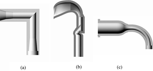
Currently, the pharmaceutical industry mainly uses solid walled models as a representative of the adult mouth-throat to estimate the filtering effect of the actual human mouth-throat. An essential requirement for these physical models of the mouth-throat is that they should mimic the average deposition curve obtained from realistic human mouth-throats during in vitro tests for drug formulations and inhalation device designs. A number of such in vitro mouth-throat models have been developed for this purpose. The United States Pharmacopoeia (USP 2000) defines a 90° elbow consisting of two straight tubes as being representative of the mouth-throat. A schematic of this model is shown in . However, as elucidated by CitationZhang et al. (2004), the USP mouth-throat usually underestimates monodisperse aerosol deposition efficiency in the mouth-throat when compared to the in vivo average curve (CitationStahlhofen et al. 1989). Another model of the human mouth-throat with more complicated geometry following the average dimensions of the extrathoracic region in a group of human subjects has been originally developed by CitationStapleton et al. (2000), and was designed to resemble the shape of an actual human mouth-throat more closely than the USP mouth-throat. It has been referred to as the idealized mouth-throat or the “Alberta geometry.” A schematic of the idealized mouth-throat is shown in . Early experimental work with this idealized mouth-throat model has been done by CitationDeHaan and Finlay (2001). Extensive measurements were provided by CitationGrgic et al. (2004) and CitationDeHaan et al. (2004), which were complemented by PIV fluid flow measurements (CitationHeenan et al. 2003) and numerical modeling work (CitationMatida et al. 2004). The effect of inhaler mouth piece geometry was elucidated by CitationDeHaan and Finlay (2004). These studies showed that the idealized mouth-throat gives good agreement with the in vivo deposition curve. However, the geometry of the idealized mouth-throat used in these previous studies is still rather complex to specify and time consuming to produce. Thus, it is expected that a simpler highly idealized representation of the mouth-throat region is desirable in the pharmaceutical field when drug formulations or inhalation devices are tested. Such a highly idealized mouth-throat should be less expensive, easier to manufacture, and easier to collect drug for chemical assays when compared to more realistic mouth-throats. The drawbacks mentioned above for existing mouth-throat models are the prime motivation for the development of a new geometry for the mouth-throat. A novel model of the mouth-throat, namely the “highly idealized mouth-throat,” has been proposed and developed by CitationZhang et al. (2004), which was designed following previous studies on particle deposition in curved pipes (CitationPui et al. 1987). A schematic of this model is shown in . Preliminary studies by CitationZhang et al. (2004) in this model using monodisperse aerosols indicate that it closely reproduces the average mouth-throat deposition curve obtained from human subjects (CitationStahlhofen et al. 1989).
FIG. 1 Schematic of the mouth-throats (a) the USP mouth-throat, (b) the idealized mouth-throat, (c) the highly idealized mouth-throat.
In light of the complexity of the idealized mouth-throat and the inadequacy of the USP mouth-throat in reproducing deposition efficiency of the human mouth-throat, the highly idealized mouth-throat presents a solution to both shortcomings. The highly idealized mouth-throat with its simple geometrical design is easy to fabricate and allows automated washing procedures. In this present study, a major aim is to extend the preliminary finding of the highly idealized mouth-throat model and propose an optimized geometry based on the additional experimental data obtained. It is expected that the present study will be useful in considering the highly idealized mouth-throat as a possible pharmaceutical industry standard for representing mouth-throat filtering in a flow rate range of 30–90 l/min, which nearly covers the typical average flow rate range of 20–100 l/min for dry powder inhalers (CitationClark and Hollingworth 1993).
2. METHODOLOGY
2.1. Highly Idealized Mouth-Throat Geometries
The prototype design of the highly idealized mouth-throat consisted of a circular “mouth” of 50 mm length and 30 mm diameter followed by a contraction nozzle of 45 mm length, which smoothly connected the mouth model with a 90° curved pipe of 8.5 mm inner diameter and a curvature radius of 47.7 mm (CitationZhang et al. 2004). This design was partially based on the experimental study of particle deposition in curved pipes by CitationPui et al. (1987).
Since deposition characteristics are especially sensitive to the inner diameter of the curved pipe (CitationPui et al. 1987; CitationMcFarland et al. 1997), it is expected that variations in the inner diameters of the bend region of the highly idealized geometry will give different particle deposition characteristic curves. This point is readily understood by realizing that smaller cross sectional areas give rise to increased magnitudes of velocity profiles in the curved pipe, which increase the inertia of aerosol particles, causing more deposition by inertial impaction in the bend. In this study, we will attempt to propose an optimized geometry for the highly idealized mouth-throat by experimentally measuring monodisperse particle deposition in six highly idealized mouth-throats with different diameters of the bends.
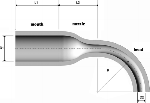
A detailed schematic of the highly idealized mouth-throat is shown in , where D1 = 30 mm is the inlet diameter of the “mouth,” D2 is the outlet diameter of the curved pipe, L1 = 50 mm is the length of the “mouth,” L2 = 45 mm is the length of the nozzle connecting the mouth and the bend, and R = 50 mm is the radius of curvature of the bend. The only difference among these models is the diameters D2 of the bends; hence, the models will be intuitively referred to by their bend diameters D2 (10.0 mm, 9.0 mm, 8.5mm, 8.0 mm, 7.5 mm, and 7.0 mm). The choice of the curved pipe diameters of the six mouth-throat models is based on theoretical calculations using an empirical correlation proposed by CitationPui et al. (1987), which is based on inertial particle deposition studies in curved pipes.
Manufacturing of the mouth-throat models was done using Stereo-Lithography (Model FDM 8000, Stratasys, Eden Prairie, MN, USA) with Acrylonitrile-Butadiene-Styrene (ABS) plastic. Each set of the highly idealized mouth-throat models included two components: the mouth and bend. An additional filter adapter was used to connect both the bend and filter. Each bend consisted of two halves, which could be connected along the sagittal plane and then wrapped by parafilm (Pechiney Plastic Packaging, Inc. Menasha, WI, USA) to create an airtight seal. The model outer surfaces were coated with an airtight epoxy layer to obtain high chemical and physical resistance (CitationDeHaan and Finlay 2004). In addition, the inside walls of the models were painted with fluorocarbon coating EGC1700 (3M, St. Paul, MN, USA) to increase liquid-surface contact angle, thus preventing the surface from wetting and increasing the maximum mass per unit wall area that the geometry can hold (CitationGrgic et al. 2004).
2.2. Experimental Procedure
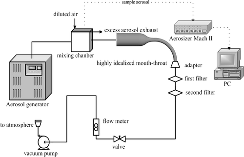
A schematic of the experimental setup is shown in . Monodisperse aerosol of di-2-ethylhexylsebacate (DEHS) oil was generated using a Condensation Monodisperse Aerosol Generator (CMAG, Model 3457, Topas, Germany). The aerosol stream from the exit of the generator was diluted with extra ambient air to decrease the concentration of the aerosol. Aerosol particle sizes and monodispersity were monitored using an Aerosizer Mach II (TSI Inc., Amherst, MA, USA). Monodisperse particles with mass median diameters of 2.1–7.5 μ m (GSD < 1.1) were selected for this study. Test aerosol was driven by a vacuum pump (Model 0523-101Q-G588DX, Gast manufacturing Inc., Benton Harbour, MI, USA). Aerosol flowed into the test models through a straight tube of 17.3 mm in diameter and 800 mm in length, which was aligned along the symmetric central line of the inlet of the model mouth. Two Marquest Respirguard filters (Marquest Medical Products, Inc., Boulder, CO., USA) were connected in series at the outlet of the model. Two steady inhalation flow rates of 30 and 90 l/min were used in the experiments. Specific flow rates were regulated using a needle valve downstream of the filters. Extra aerosol was exhausted to the atmosphere by an exhausting hose plugged into the main mixing chamber. Typical running periods varied from 20 s to 10 min, and optimum time was determined by particle deposition rate and net mass of oil that the model surface could “hold” before flooding the inner wall.
Gravimetry was used to determine particle deposition in the models. Each component was weighed using an analytical balance (Sartorius, 1207MP2, Germany) before and after each test. The total deposition efficiency (η t ) is given by:
2.3. CFD Simulations
2.3.1. Primary Flow Solution
Geometries of the highly idealized mouth-throat models were created using Pro/Engineer (PTC, Needham, MA, USA), then the surfaces were exported as a standard data interface (IGES) file. The unstructured meshes were created using CFX Builder mesh generator (Version 5.6 and 5.7, ANSYS Inc., Canonsburg, PA, USA), which implements Advancing Front and Inflation (AFI) volume. In near wall regions, inflated volume was used to resolve velocity gradients caused by boundary layer effects.
In this CFD study, the governing equations of fluid flow were solved using a commercial finite volume based CFX5 software package (Version 5.6 and Version 5.7, ANSYS Inc., Canonsburg, PA, USA). Because flows in the mouth-throat can be turbulent, a standard version of k − ω turbulent closure model developed by CitationWilcox (1988) was used. A wall function approach was adopted to treat wall boundary layer effects.
In the present calculation, the 10.0 mm, 8.5 mm, and 7.0 mm mouth-throats were chosen as the testing models for grid convergence. A number of grid sizes (403,642, 734,206, 1,180,400, and 1,739,688 elements for the 10.0 mm model, 836,185, 1,178,515, and 1,761,119 elements for the 8.5 mm model, and 1,257,933, 1,569,848, and 2,157,727 elements for the 7.0 mm model) generated from the three mouth-throat models mentioned above were used to determine grid convergence errors. The total particle deposition efficiency, pressure drop through the mouth-throat and the magnitudes of mean velocities at two specific cross-sections were chosen to examine grid convergence. The calculation results showed that grid convergence was achieved since the above parameters for the different grid sizes indicated differences less than 5% in the above selected parameters when refining the grid sizes. The grid properties for all six highly idealized mouth-throats are listed in .
TABLE 1 Grid properties for CFD simulation of the six highly idealized mouth-throats
For boundary conditions, steady flow rates of 30 and 90 l/min were prescribed as inlet conditions. A turbulence intensity of 5% of the mean velocity was set at the inlet and increasing (to 10%) or decreasing (to 1%) this turbulence inlet parameter caused deposition results to vary by < 3%. A Dirichlet zero gauge pressure condition at the outlet was applied.
The computations were performed on a Desktop Computer with a 1.8 GHz P4 processor and 1.0 GB RAM. Typical run time for the fluid flow was approximately 12–18 hours.
2.3.2. Particle Tracking
The particle tracking algorithm available in CFX (Version 5.7, ANSYS Inc., PA, USA), the “mean flow” particle tracking model, was used here. It has been demonstrated that this model gives particle deposition predictions superior to the “turbulence” particle tracking model (CitationMatida et al. 2004; CitationZhang et al. 2004). The basic assumptions in the Lagrangian tracking model include: no particle-particle interactions, no particle source terms to the turbulence equations, and spherical particles. In our experiments, volume fractions of particles were usually maintained on the order of 10−6 or below. The mean distance between the particles was almost an order of magnitude larger than the diameter of individual particles. Therefore, particle motion can be treated as having negligible effect on the fluid motion (CitationFinlay 2001). Furthermore, the material of aerosol particles (DEHS oil) is inert and has low vapor pressure, and thus, the effect of evaporation on the particle size is minor. Therefore, the above assumptions are reasonable. Mono-sized particles of 1, 2, 3, 4, 6, 7, 8, 9, and 10 μ m and density ρ = 0.912 g/cm3 were used for simulations of particle deposition. Initial particle velocities were set equal to those of the fluid and one-way momentum coupling was assumed between the air and particle phase. In each simulation, 10,000 particles were released from the inlet of the mouth-throat. A uniform distribution of particles over the entire cross-sectional area of the inlet was assumed. Increasing the number of particles released was examined, but found to have minor effect on the results.
Particle deposition in the mouth-throat can be quantified in terms of the deposition efficiency (η DE ), which is defined as:
3. RESULTS AND DISCUSSION
3.1. CFD Simulation Results
3.1.1. Air Flow Structure in the Mouth-Throats
Typical magnitudes of air flow velocities and turbulence kinetic energy at the symmetry mid-plane of the six highly idealized mouth-throats are displayed in and . As shown in , at a flow rate of Q = 30 l/min, the flow patterns in the mouth-throats indicate a similar structure. The near wall region of the mouth is dominated by low velocities. When air enters into the nozzle, it accelerates due to the decreased cross-sectional areas. A skewed velocity profile toward the outer wall can be seen in the bend. The closer to the outer wall, the higher the magnitude of the velocities. This flow structure is the result of interactions of the boundary layer, secondary flow and centrifugal effects caused by the curvature of the bend. Magnitudes of the velocities also increase with decreasing diameter of the bends. Significantly higher turbulence kinetic energy levels can be seen in the bends, especially in the shear layer near to the wall. Higher velocities combined with turbulence kinetic energy intensity could play an important role in determining particle deposition within the mouth-throat models.
FIG. 4 Magnitudes of the velocities and turbulent kinetic energy at the symmetric plane of the six highly idealized mouth-throat models (Q = 30 l/min).
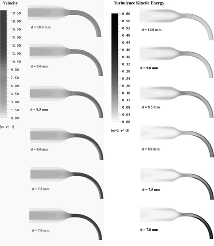
FIG. 5 Magnitudes of the velocities and turbulent kinetic energy at the symmetric plane of the six highly idealized mouth-throat models (Q = 90 l/min).
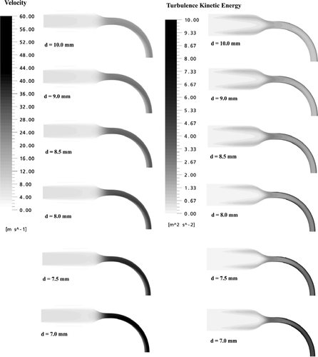
As indicated in , at a flow rate of Q = 90 l/min, the flow structure and turbulence kinetic energy distribution are similar to the case of Q = 30 l/min. However, since the velocity magnitude is enhanced, the inlet jet caused by the mouth piece extends a farther distance and even enters the nozzle.
3.1.2. Particle Deposition Efficiency in the Mouth-Throats
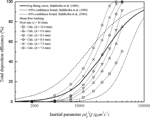
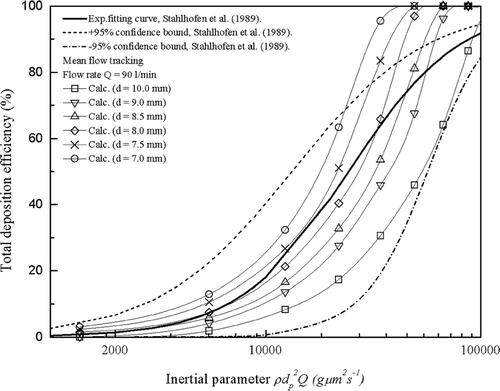
Prediction results of particle deposition from the CFD simulations excluding turbulence dispersion are shown in and . Total deposition efficiencies in the mouth-throats are plotted as a function of the inertial parameter ρ d p 2 Q (gμm2s−1), where ρ (g/cm3) is the particle density, d p (μm) is the particle diameter and Q (cm3/s) is the inhalation flow rate. For the two flow rates of 30 and 90 l/min, the deposition curves lie within the ±95% confidence bounds of the in vivo data and follow the in vivo curves over a large domain, and thus provide theoretical evidence supporting one of these mouth-throats as a surrogate optimized geometry. However, at high inertial parameter, the CFD predictions indicate significantly higher deposition efficiency than seen in vivo. An important point derived from the CFD simulations is that the deposition curve can be manipulated by changing bend diameter. Although the CFD results indicate that selecting a highly idealized geometry from the range of bend region diameter explored here may allow a reasonable in vitro-in vivo correlation to be obtained, a previous publication (CitationZhang et al. 2004) indicated that CFD simulation may be somewhat inaccurate in duplicating particle deposition in the present geometry. In particular, particle tracking models including turbulence dispersion usually over-predict particle deposition, while particle tracking models excluding turbulence dispersion typically underpredict deposition. A complex correction of the effect of turbulence fluctuations on particle deposition is needed, but it is beyond the scope of this study. For this reason, we turn to experiment to further examine deposition in these highly idealized geometries.
3.2. Experimental Results
3.2.1. Particle Deposition in the Highly Idealized Mouth-Throat Models
The experimental particle deposition efficiencies of the six highly idealized mouth-throat models at a flow rate of 90 l/min are compared against average in vivo data collected by CitationStahlhofen et al. (1989) in . As the flow rate is constant, differences in inertial parameter are due only to differences in the particle size. Larger particle sizes give higher deposition efficiencies across all models, while within models smaller bend diameters give higher deposition efficiencies for identical particle sizes. The two results are consistent with what is expected based on the knowledge of inertial deposition and also agree with previous observations that particle deposition in curved pipes is dominated by inertial impaction (CitationPui et al. 1987; CitationMcFarland et al. 1997).
FIG. 8 Total deposition efficiency as a function of inertial parameter in the six mouth-throat models at the flow rate of 90 l/min. Each point represents the average of three repeats and error bars refer to standard deviation.
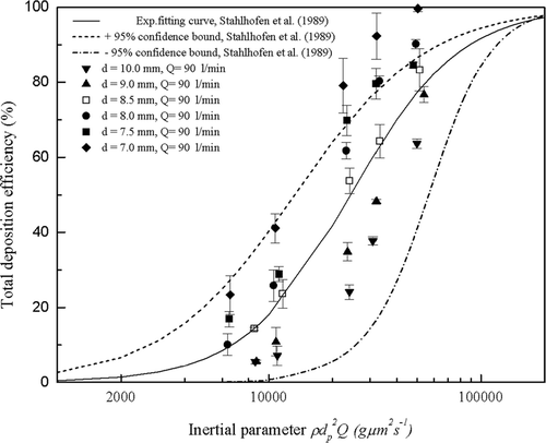
The six highly idealized mouth-throat models are seen to duplicate the trend of the in vivo data and have been well chosen to span the average in vivo curve and the ± 95% confidence bounds and provide a basis for proposing an optimized geometry. The 8.5 mm model is seen to agree within error with the average in vivo data (CitationStahlhofen et al. 1989), while the 10.0 mm and 9.0 mm models underestimate the average in vivo data, and the 7.0 mm, 7.5 mm, and 8.0 mm models overestimate the average in vivo data.
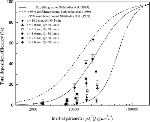
In contrast, the experimental total deposition efficiencies of the six highly idealized mouth-throat models at a flow rate of 30 l/min are compared against in vivo data in . As shown, at a lower flow rate of 30 l/min, we no longer see the data following the in vivo curve for each model. However, it is still apparent that smaller cross sections and higher inertial parameters give rise to higher deposition efficiencies, which is expected for inertial deposition in curved pipes. The deposition efficiencies are lower than average in vivo values for all six models except the 7.0 mm model. With the exception of the 7.0 mm model, all other models exhibit deposition efficiencies much lower than the average in vivo curve, but still lying within the ±95% confidence bounds of the in vivo data. This unexpected result limits the versatility of the proposed 8.5 mm optimized geometry which reproduces the in vivo data at high flow rates, but not at low flow rates such as 30 l/min. This suggests that a different optimized geometry exists for low flow rates.
3.3. Discussion
As seen in , the present experimental results suggest that a highly idealized mouth-throat model with a bend diameter of 8.5 mm is the optimized geometry which most closely reproduces the average in vivo data at 90 l/min, and also presumably at other high flow rates close to 90 l/min. It should be noted that the data for the 10.0 and 9.0 mm models also lie entirely within the ± 95% confidence bounds of the in vivo data and, along with the 8.5 mm model, reproduce the in vivo data better than the current USP standard mouth-throat (CitationZhang et al. 2004).
However, data in suggests that a different optimized geometry exists for a lower flow rate of 30l/min. This point seems to be consistent with the characteristics of actual human mouth-throat geometries since the dimensions of a real human airway tract are time dependent and adjust according to variations in flow rate. Therefore, a physical model of the mouth-throat might be expected to also observe this nature. With the current experimental data, it is speculated that, at a flow rate of 30 l/min, an optimized geometry of the present shape will have a bend diameter between 7.0 and 7.5 mm. The need to have different highly idealized geometries at different flow rates detracts from the use of these geometries as a standard geometry for inhaler testing. It should be noted that the idealized mouth-throat (“Alberta geometry”) (CitationGrgic et al. 2004) does not suffer from this drawback and despite its more complex shape is more desirable in this regard. It should also be noted that the curve for each mouth-throat model seems not to follow the in vivo curve over the entire range of the inertial parameter. Therefore, it appears that these highly idealized mouth-throat models can be employed accurately in a limited particle size and flow rate range.
The present work also confirms that inertial impaction is the dominant deposition mechanism in the present mouth-throat geometries for large size particles. However, the inertial parameter ρ d p 2 Q does not take into account the geometry of the employed mouth-throat model, thus neglecting the variation of cross-sectional areas within the models. Instead, the Stokes number (Stk), which takes into account the flow velocity and geometry of the model tested, can be used. For our purposes, the Stokes number is calculated as
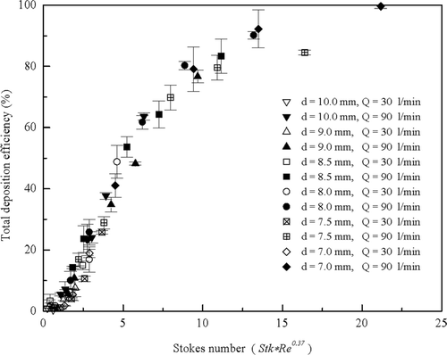
Because in vivo geometric data is unavailable for calculating Stokes number, average in vivo data could not be plotted as a function of the Stokes number. Total deposition efficiencies as a function of the Stokes number for all highly idealized mouth-throats collected at both flow rates of 30 and 90 l/min are presented in . The data from the two flow rates appear to lie on two different curves, with the lower flow rate displaying lower deposition efficiencies for the same Stokes number. This discrepancy suggests that there is another factor besides the Stokes number affecting deposition efficiencies. A similar discrepancy was observed in the idealized mouth-throat model studied by CitationGrgic et al. (2004) and was speculated to be due to a Reynolds number effect. Following the empirical correlation suggested by CitationGrgic et al. (2004), Stokes number is multiplied by Reynolds number to the power of 0.37. is replotted in with this Reynolds number correction. It is found that particle deposition in the mouth-throats collapse closely onto a single curve.
FIG. 10 Total deposition efficiency as a function of the Stokes number of the six highly idealized mouth-throat models at flow rates of 30 and 90 l/min.
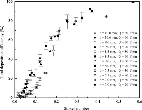
FIG. 11 Total deposition efficiency as a function of the Stokes number is replotted with x-axis including a Reynolds number correction.
The major reason for this Reynolds number effect may be attributed to the effects of the shape of velocity profiles. While the Reynolds number characterizes flow pattern through straight tubes, the Dean number is the equivalent for characterizing flow through bends of circular tubing (CitationMcFarland et al. 1997). Low flow rates correspond to low Reynolds and Dean numbers, which indicate laminar flow, and high flow rates correspond to high Reynolds and Dean numbers, which indicate turbulent flow (CitationMcFarland et al. 1997).
The Reynolds number (Re) is given by
For the 8.5 mm model, the Dean number (De) is determined to be 1412 at a flow rate of 30 l/min and 4240 at a flow rate of 90 l/min. However, the critical Dean number that determines the flow transition from laminar to turbulent flow in curved tubes
is difficult to determine since it depends on many factors, including oncoming flow state, surface roughness and secondary flows. Previous studies have quoted critical Dean numbers as low as 370 and as high as 2948 (CitationMcFarland et al. 1997). It is also known that turbulent flow is more difficult to initialize and maintain in smaller diameter curved tubes due to the effect of secondary flow (CitationMcFarland et al. 1997). Therefore, the critical Dean number of the curved pipe in a geometry such as the highly idealized mouth-throat model is expected to be relatively higher. As elucidated by CitationGrgic et al. (2004), in the idealized mouth-throat, when the flow Reynolds number varies, the flow boundary layer thickness varies as well. With increasing flow rate, the velocity profile changes shape from parabola to top hat (plug flow). As a result, decreasing Reynolds number results in an increasing thickness of the boundary layer. Although actual velocity profiles are complicated in the highly idealized mouth-throat due to its curved shape and the presence of secondary flows, this effect should be similar. However, determination of the actual velocity profile in the highly idealized mouth-throat model involves measurements using Particle Image Velocimetry (PIV) or hot wire anemometer, which is beyond the scope of this study.
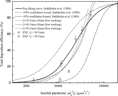
A comparison of experimental data and CFD results in the 8.5 mm mouth-throat model is plotted in . As shown, the CFD simulation result captures the main trend of particle deposition varying with the inertial parameter and gives a prediction of particle deposition that is relatively close to the experimental data. However, due to weaknesses of the mean flow particle tracking model used, as elucidated in a study by CitationMatida et al. (2004), the effects of turbulence on particle deposition are not captured adequately, and no Reynolds number effect is seen in the results of the CFD simulation.
4. SUMMARY
In this study, monodisperse particle deposition was measured in six highly idealized mouth-throats with different bend diameters. At both high (90 l/min) and low (30 l/min) flow rates, deposition efficiencies were observed to be higher for larger particles and for smaller cross sections of the curved pipe in the highly idealized mouth-throats. These two observations agree with previous findings that inertial impaction deposition is the dominant process in curved pipes and may be useful for modeling deposition in the human mouth-throat.
At a high flow rate of 90 l/min, all six models were seen to span and follow the trend of in vivo data obtained from human subjects. A highly idealized mouth-throat model with a bend diameter of 8.5 mm was proposed as the optimized geometry for high flow rates. However, at a low flow rate of 30 l/min, all models, except the 7.0 mm model, revealed deposition efficiencies that were lower than expected and it was found that the geometry optimized for high flow rates did not replicate in vivo data at low flow rates. With the experimental data obtained, it was speculated that the optimized geometry for low flow rates would have a bend diameter between 7.0 and 7.5 mm. This partially limits the versatility of the highly idealized mouth-throat, particularly compared to the Alberta geometry of CitationStapleton et al. (2000) which does not suffer from this drawback (CitationGrgic et al. 2004).
Using the Stokes number (Stk), which takes into account the flow velocities and the geometry of the models tested, it was seen that a discrepancy existed between the deposition characteristics at high and low flow rates, which could not be explained by inertial impaction deposition alone. This suggested that a Reynolds number effect was present, which has been observed in previous work (CitationGrgic et al. 2004). It was thus hypothesized that the shape of velocity profile is responsible for this Reynolds effect. However, a determination of the actual velocity profiles and flow pattern regime were beyond the scope of this study.
Although limited versatility between high and low flow rates does not convincingly establish the unique highly idealized mouth-throat model as a potential industry standard, the remarkable agreement of the optimized, but still very simple geometry for high flow rates suggests that a different optimized geometry for low flow rates can be determined. Therefore, it may be possible that two optimized highly idealized geometries will be able to estimate extrathoracic deposition for the flow rate range of 30–90 l/min.
In summary, an adequately designed highly idealized mouth-throat can closely mimic in vivo mouth-throat deposition. For different flow rates between 30–90 l/min, highly idealized mouth-throats with different key dimensions are required to accurately reproduce the in vivo average curve.
Acknowledgments
The financial support of Alberta Ingenuity Fund and NSERC is gratefully acknowledged.
REFERENCES
- Cass , M. R. L. , Brown , J. , Ickford , P. , Fayinka , S. , Newman , P. S. , Johansson , J. C. and Bye , A. 1999 . Pharmacoscintigraphic Evaluation of Lung Deposition of Inhaled Zanamivir in Healthy Volunteers . Clin. Pharmacokinetics , 36 ( Suppl.1 ) : 21 – 31 . [CSA]
- Clark , A. R. and Hollingworth , A. M. 1993 . The Relationship Between Powder Inhaler Resistance and Peak Inspiratory Conditions in Healthy Volunteers Implications for In Vivo Testing . J. Aerosol Med. , 6 : 99 – 110 . [PUBMED] [INFOTRIEVE] [CSA]
- DeHaan , W. H. and Finlay , W. H. 2001 . In Vitro Monodisperse Aerosol Deposition in a Mouth and Throat with Six Different Inhalation Devices . J. Aerosol Med. , 14 ( 3 ) : 361 – 367 . [PUBMED] [INFOTRIEVE] [CROSSREF] [CSA]
- DeHaan , W. H. and Finlay , W. H. 2004 . Predicting Extrathoracic Deposition from Dry Powder Inhalers . J. Aerosol Sci. , 35 : 309 – 331 . [CROSSREF] [CSA]
- Emmett , P. C. , Aitken , R. J. and Hannan , W. J. 1982 . Measurements of the Total and Regional Deposition of Inhaled Particles in the Human Respiratory Tract . J. Aerosol Sci. , 13 : 549 – 560 . [CROSSREF] [CSA]
- Finlay , W. H. 2001 . The Mechanics of Inhaled Pharmaceutical Aerosols: An Introduction. , London : Academic Press .
- Finlay , W. H. , Zhang , Y. , Grgic , B. , Heenan , A. , Burnell , P. , Matida , E. A. , Pollard , A. and Lange , C. F. 2004 . “ Solving a Major In Vitro-In Vivo Correlation Problem: Impactor Induction Ports ” . In Respiratory Drug Delivery IX , Edited by: Dallby , R. N. , Byron , P. R. , Peart , J. , Suman , J. D. and Farr , S. J. volume I , pages 203 – 210 . River Grove, Illinois, USA : Palm Desert, Califonia. Respiratory Drug Delivery, Davis Healthcare Intnational Publishing, LLC .
- Foord , N. , Black , A. and Walsh , M. 1978 . Regional Deposition of 2.5–7.5 μ m Diameter Inhaled Particles in Healthy Male Non-Smokers . J. Aerosol Sci. , 9 : 343 – 357 . [CROSSREF] [CSA]
- Grgic , B. , Finlay , W. H. and Heenan , A. F. 2004 . Regional Aerosol Deposition and Flow Measurements in an Idealized Mouth and Throat . J. Aerosol Sci. , 35 : 21 – 32 . [CROSSREF] [CSA]
- Heenan , A. F. , Matida , E. A. , Pollard , A. and Finlay , W. H. 2003 . Experimental Measurements and Computational Modeling of the Flow in an Idealized Extrathoracic Airway . Exp. Fluids. , 35 : 70 – 84 . [CROSSREF] [CSA]
- Matida , E. A. , Finlay , W. H. , Lange , C. F. and Grgic , B. 2004 . Improved Numerical Simulation of Aerosol Deposition in an Idealized Mouth-Throat . J. Aerosol Sci. , 35 : 1 – 19 . [CROSSREF] [CSA]
- McFarland , A. R. , Gong , H. , Muyshond , A. , Wente , W. B. and Anand , N. K. 1997 . Aerosol Deposition in Bends with Turbulent Flow . Environ. Sci. Technol. , 31 ( 12 ) : 3371 – 3377 . [CROSSREF] [CSA]
- Pui , D. Y. H. , Novas , F. R. and Liu , B. Y. H. 1987 . Experimental Study of Particle Deposition in Bends of Circular Cross Section . Aerosol Sci. Technol. , 7 : 301 – 315 . [CSA]
- Stahlhofen , W. , Gebhart , J. and Heyder , J. 1980 . Experimental Determination of the Regional Deposition of Aerosol Particles in the Human Respiratory Tract . Am. Ind. Hyg. Assoc. J. , 41 ( 6 ) : 385 – 398a . [PUBMED] [INFOTRIEVE] [CSA]
- Stahlhofen , W. , Gebhard , J. and Heyder , J. 1981 . Biological Variability of Regional Deposition of Aerosol Particles in the Human Respiratory Tract . Am. Ind. Hyg. Assoc. J. , 42 : 348 – 352 . [PUBMED] [INFOTRIEVE] [CSA]
- Stahlhofen , W. , Gebhard , J. , Heyder , J. and Scheuch , G. 1983 . New Regional Deposition Data of the Human Respiratory Tract . J. Aerosol Sci. , 14 : 186 – 188 . [CROSSREF] [CSA]
- Stahlhofen , W. , Gebhard , J. , Heyder , J. , Scheuch , G. and Juraske , P. 1984 . Particle Deposition in Extrathoracic Airways of Healthy Subjects and of Patients with Early Stages of Laryngeal Carcinoma . J. Aerosol Sci. , 15 : 115 – 117 . [CSA]
- Stahlhofen , W. , Rudolf , G. and James , A. C. 1989 . Intercomparison of Experimental Regional Aerosol Deposition Data . J. Aerosol Med. , 2 ( 3 ) : 285 – 308 . [CSA]
- Stapleton , K. W. , Guentsch , E. , Hoskinson , M. K. and Finlay , W. H. 2000 . On the Suitability of k-ϵ Turbulence Modeling for Aerosol Deposition in the Mouth and Throat: A Comparison with Experiment . J. Aerosol Sci. , 31 ( 6 ) : 739 – 749 . [CROSSREF] [CSA]
- Wilcox , D. C. 1988 . Reassessment of the Scale Determining Equation for Advanced Turbulence Models . AIAA J. , 26 ( 11 ) : 1299 – 1310 . [CSA]
- Zhang , Y. , Finlay , W. H. and Matida , E. A. 2004 . Particle Deposition Measurements and Numerical Simulation in a Highly Idealized Mouth-Throat . J. Aerosol Sci. , 35 : 789 – 803 . [CROSSREF] [CSA]
