Nanoparticle penetration efficiencies through five different coils of circular cross-sections were measured as a function of particle size, Dean number, and curvature ratio of coil. Silver particles with diameters ranging from 3 to 50 nm were used, and the Dean number was varied from 21 to 1779. According to the equation of critical Reynolds number for the coil (CitationIto 1959), all the flows in this study were laminar. The penetration efficiency through coils was found to increase with increasing particle size and also with increasing Dean number. The influence of curvature ratio on penetration efficiency seemed to be negligible when the Dean number was greater than approximately 200. Secondary flow developed due to centrifugal force in the coil is known to increase diffusional particle loss. Boundary layer thickness (δ) of the secondary flow can affect the particle loss in coils, because the average flow velocity of secondary flow within the boundary layer is related to δ. The particle loss in coils is assumed to be a byproduct of secondary flow and Brownian diffusion. As a result, a non-dimensional parameter (ζ) to explain the particle loss in coils was defined as ζ = δ × ξ, where ξ is the dimensionless parameter proposed by CitationGormley and Kennedy (1949) for describing the particle loss due to Brownian diffusion in a straight cylindrical tube. An empirical equation of the nanoparticle penetration efficiency through coils in laminar flow regime was suggested as a function of the new coil parameter, ζ.
1. INTRODUCTION
In many practical applications, aerosol transportation lines are composed of curved pipes, such as bends and coils. For the flows through straight cylindrical tubes, convection occurs only in axial direction. In addition to this, radial and tangential velocities do exist for the flows through curved pipes, because the fluid experiences a centrifugal force when it flows along the curvature of the curved pipe. As a result, a secondary flow develops in any cross-sectional plane perpendicular to the axis, and the axial velocity profile is no longer symmetric and is skewed to the outer wall. The secondary flow is known to increase the diffusional particle loss by bringing the particles from cross-sectional center area to tube wall.
It is well known that the dimensionless Dean number can be used to characterize the flows through the curved pipes (CitationMori and Nakayama 1965; CitationPui et al. 1987; CitationTsai and Pui 1990; CitationSato et al. 2003). The Dean number is the ratio of the square root of the product of inertial and centrifugal forces to the viscous force, and plays a role of Reynolds number for the flows through curved pipes. The Dean number is defined as
CitationPui et al. (1990) developed a compact coiled denuder to separate reactive gases from the particles and evaluated its performance. They defined a new parameter that contains the mean mass-transfer Sherwood number, and derived a semi-empirical equation from their experimental measurements using this parameter. Their Dean number was ranged approximately from 330 to 550. CitationWang et al. (2002) measured the penetration efficiencies of nanoparticles through 90° bends and Swagelok elbows which are commonly used in aerosol sampling instruments. They used very fine particles ranging from 5 to 15 nm, and showed that the penetration efficiencies through the smooth 90° bends were slightly higher than those through the Swagelok elbows. This implies that the nanoparticle penetration efficiency through curved pipes may be affected by the curvature ratio (R 0) or the Dean number.
After CitationGormley and Kennedy (1949) had first derived an analytic solution for diffusional particle loss in a straight cylindrical tube, many researchers found formulae of penetration efficiencies of fine particles through different shapes of airways, such as rectangular channels, parallel circular plates, and annular tubes (CitationMercer and Mercer 1970; CitationTan and Thomas 1972; CitationPossanzini et al. 1983). The penetration efficiencies through the various types of tubes were derived using dimensionless parameters which are similar to that of CitationGormley and Kennedy (1949),
In the present work, efforts are made to investigate wider ranges of the Dean number and the particle size than those in the previous studies. It is assumed that the secondary flow and Brownian diffusion are the main mechanisms for particle loss in coils. The objectives of this study is firstly to find a dimensionless parameter to describe particle loss in coils by modifying the Gormley and Kennedy's parameter (ξ), and secondly to suggest an empirical equation of the nanoparticle penetration efficiency through coils of circular cross-sections in laminar flow regime.
2. EXPERIMENTAL
2.1 Description of the System
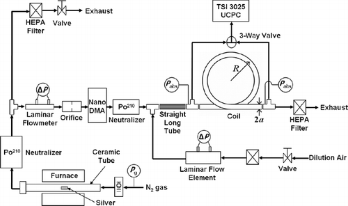
The experimental setup is shown in . The evaporation/condensation method was used to produce nanometer sized particles as described by CitationScheibel and Porstendörfer (1983) and CitationBartz et al. (1987). An electric tube furnace (Model HTF55322A, Lindberg/Blue M) was used to control the temperature inside a ceramic tube (Al2O3, OD 0.750″, ID 0.562″, 35″ long). Nitrogen (N2) was introduced into the tube as carrier gas at the gauge pressure of 69 kPa, and its flow rate was controlled by a rotameter (Cole-Parmer). A ceramic boat was filled with silver powder (purity 99.999%, Johnson Matthey Electronics) and placed in a ceramic tube inside the furnace. Two Swagelok Ultra-Torr Vacuum Fittings were used to seal the ends of the ceramic tube. Both fittings were approximately 6 inches away from the furnace heating zone in order to prevent rubber sealing rings from melting at high temperatures.
The particle size distribution is affected by the vapor concentration and the coagulation rate in the furnace heating zone. By varying the furnace temperature, the concentration of the silver vapor can be controlled. If the vapor concentration is constant at a fixed furnace temperature, the coagulation rate is affected by the residence time of the vapor in the cooling zone and also by the cooling rate with a quenching gas. Since the flow rate going into the ceramic tube was fixed at 3 L/min in this experiment, the furnace temperature was the only one parameter for controlling the particle size distribution. The quenching process was omitted in order to obtain a particle concentration as high as possible, because the room temperature was kept at 20°C and the aerosol was effectively cooled down before it reached the first neutralizer.
The aerosol was neutralized using a Po210 radioactive source, and the flow was bisected. A needle valve at the exhaust line was used to control the aerosol flow rate going into a Nano-DMA. An orifice was used as a flow restrictor at the upstream of the Nano-DMA. The airborne particles were classified using the Nano-DMA system as described by CitationChen et al. (1998). The test particle sizes were ranged from 3 to 50 nm. The monodisperse aerosol from the Nano-DMA was neutralized again with another Po210 radioactive source and diluted with clean air. The total flow rates of the monodisperse aerosol plus the dilution air were 1.0, 5.0, 10.0, 15.0, and 20.0 L/min. The diluted monodisperse aerosol flowed through a straight long stainless steel tube of the same inner radius as the coil to be tested, so the flow was assumed to be fully developed before being introduced into the coil. An Ultrafine Condensation Particle Counter (UCPC Model 3025A, TSI) was used to measure the particle concentration. Sampling flow rate of the UCPC was 0.3 L/min only when the aerosol flow rate through the coil was 1.0 L/min, otherwise it was 1.5 L/min. A 3-way valve was used to guide the upstream or the downstream aerosol to the UCPC. Transportation lines from both ends of the coil to the 3-way valve were identical, so the particle losses in measuring the upstream and the downstream concentrations were assumed to be same. When measuring the downstream particle concentration, no flow could go through the upstream sampling line because of the 3-way valve. Therefore, the T-junction at the upstream of the coil would not affect the flow in the coil during the measurement of downstream particle concentration. All conductive tubes, including the coil were grounded to eliminate the effect of electrostatic charges.
2.2 Coil Dimensions and Flow Conditions
According to CitationIto (1959), a flow through a coil can be considered as being laminar, if the flow Reynolds number is smaller than a critical value which is expressed as follows.
TABLE 1 Dimensions and flow conditions for single-turn coils
2.3 Particle Size Distribution
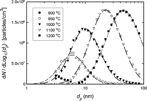
A nanometer aerosol size analyzer (nASA) developed by CitationHan et al. (2000) was used to measure particle size distributions right after the first neutralizer. The nASA is basically composed of a bipolar charger (Po210), an extended-length Nano-DMA and an electrometer (Model 3068A, TSI). The nASA has the ability to scan 30 size channels between 3 and 100 nm in 3 seconds. Because all particles classified by the Nano-DMA are charged, particle number concentration can be calculated from the measured current, carried by the particles, with the electrometer by considering the charge fraction at the bipolar charger according to particle size. Since the noise current of the electrometer was less than 2 fA, the minimum detectable number concentration of singly charged particles was about 500 cm− 3 when sampling flow rate for the electrometer was 1.5 L/min. Several particle size distributions measured by the nASA at different furnace temperatures are shown in , where the lines represent log-normal distribution fitting curves.
It was assumed that all the particles smaller than 50 nm are singly charged in the view of CitationFuchs' charging theory (1963). This assumption is valid due to the fact that the fraction of singly charged particles is approximately 20 times higher than that of doubly charged ones, for a particle size of 50 nm (CitationWiedensohler 1988). The problem, however, is that the aerosol downstream of the Nano-DMA could also contain multiply charged particles which are larger than primary particle size. It is well known that the monodispersity can be greatly enhanced by choosing the primary particles larger than the peak size of a given particle size distribution. So, several particle size distributions were measured at different furnace temperatures as shown in , and every test particle size was chosen from the right half of each size distribution. For example, in order to generate 20 nm particles with the current experimental setup, the furnace temperature was set to be 1000°C. One thing to note is that the particle size of 3 nm seems to be on the right tail of the distribution at the furnace temperature of 900°C.
3. RESULTS
3.1 Measured Nanoparticle Penetration Efficiency Through Coils
The penetration efficiency through a coil, ηC, was defined as the ratio of downstream number concentration to upstream concentration. The number concentrations were measured with the UCPC and averaged over the sampling time of 2 minutes.
Even though every coil was grounded, a charged particle flowing very near the tube wall might be deposited due to the influence of image forces. In order to eliminate all the charged particles and generate zero-charged particles, an electrostatic condenser was used right after the second neutralizer which was directly connected to the outlet of the Nano-DMA. lists the measured penetration efficiencies through a coil (R = 28.3 cm, a = 0.395 cm) for neutralized and zero-charged particles. Since the largest among the five coils was used and the flow rate was lowest (1.0 L/min), the residence time of the flow was longest and the effect of image force on the penetration efficiency was assumed to be greatest. Since the differences between the average values of two experimental data groups were very small for all test particle sizes, the effect of the image force on the penetration efficiency was assumed to be negligible. In the following experimental results, in order to obtain good statistical values by having the particle number concentration as high as possible, the electrostatic condenser was not used and the neutralized particles from the second neutralizer were introduced into the coil to be tested.
TABLE 2 Measured penetration efficiencies through a coil (R = 28.3 cm, a = 0.395 cm) for neutralized and zero-charged particles
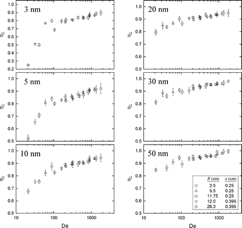
The measured penetration efficiencies of monodisperse particles through different coils are shown in as a function of the Dean number. The penetration efficiency through the coil was found to increase with increasing Dean number, namely, with increasing flow Reynolds number and decreasing curvature ratio of coil (R 0) from the definition of Dean number. The influence of R 0, however, was assumed to be negligible when the Dean number was larger than approximately 200, because the penetration efficiencies through the coils of different R and a seemed to overlap for all tested particle sizes. also shows that the penetration efficiency through the coil increased with increasing particle size, because larger particles had less diffusivity.
FIG. 3 Experimental results of penetration efficiencies through different coils according to particle size.
For the investigated particle sizes, ranging from 3 to 50 nm, Brownian diffusion was assumed to be one of the main mechanisms for the particle loss to tube wall. The penetration efficiencies of the test particles through straight cylindrical tubes can be predicted by a well-known equation derived by CitationGormley and Kennedy (1949),
A comparison of the penetration efficiencies through coils and straight tubes is shown as a function of the particle diameter in , for a flow rate of 1.0 L/min. In this graph, the data points with error bars are the measured penetration efficiencies through coils, while the lines represent the penetration efficiencies through straight tubes predicted by Equation (Equation6). The lengths (L = 2π R) and inner radii (a) of the straight tubes were assumed to be the same as those of the coils. The closed circles represent the penetration efficiencies through a coil of R = 2.5 cm and a = 0.25 cm, and the solid line illustrates the penetration efficiency through a 15.7 cm long straight tube of a = 0.25 cm. The same way of comparison was performed between the open square symbols (coil, R = 28.3 cm, a = 0.395 cm) and the dashed line (straight tube, L = 177.8 cm, a = 0.395 cm). The penetration efficiencies through the coils were lower than those through the straight tubes. This is because fine particles can easily follow the secondary flow and deviate from cross-sectional center to tube wall, as can be conjectured from . In other words, the possibility for the nanoparticles to diffuse to tube wall is increased by the secondary flow.
FIG. 4 Comparison of penetration efficiencies between coils and straight tubes for a flow rate of 1.0 L/min.
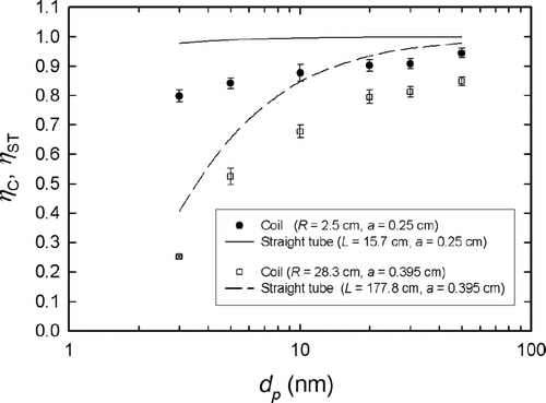
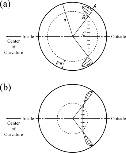
FIG. 5 Schematic diagram of the cross-sectional view of secondary flow for (a) higher Dean number (b) lower Dean number, based on the core-and-boundary-layer concept proposed by CitationMori and Nakayama (1965).
3.2 Empirical Nanoparticle Penetration Efficiency Curve for Coils in Laminar Flow Regime
CitationMori and Nakayama (1965) defined two regions of the secondary flow, i.e., core and boundary layer, as sectioned by a dotted circle in . In the core region (inside the dotted circle) viscous stress might be neglected, while it cannot be ignored in the boundary layer near the tube wall. The boundary layer thickness (δ) of secondary flow, normalized by tube inner radius (a), is a function of the Dean number and can be predicted as follows for a fully developed laminar flow in the coil (CitationMori and Nakayama 1965; CitationCheng and Wang 1981),
A schematic comparison of the secondary flow between higher and lower Dean numbers is shown in and , for a fixed tube inner radius. The flow rate of the secondary flow passing through the A-B plane has to be equal to that through the B-C plane, due to the continuity of secondary flow. According to Equation (Equation7), δ increases as the Dean number decreases. If the Dean number is higher (see ), larger amount of fluid in core region has to pass through thinner boundary layer and average flow velocity in the boundary layer is faster. To the contrary, the average flow velocity gets relatively slower when the Dean number is lower (see ), because smaller volume in core region flows through thicker boundary layer. Since the particles with lower speed may have higher possibility to diffuse to tube wall, the average flow velocity within δ can play an important role in affecting the particle loss to tube wall. In other words, the thicker the boundary layer of secondary flow is, the greater the particles loss can be. A non-dimensional parameter to describe the particle loss in coils was defined as follows by assuming that the particle loss in coils is a byproduct of secondary flow and Brownian diffusion,
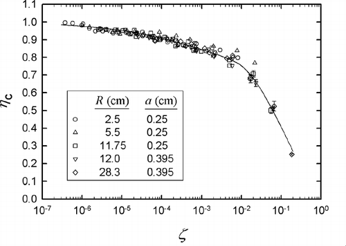
The penetration efficiencies through different coils, namely all data points in , are re-plotted as a function of this new parameter, ζ, in . Here, the diffusion coefficient (D) was calculated at the NTP condition, namely, T = 293.15 K and P = 101.325 kPa. Since the pressure drop across the coil was less than 1.31 kPa as listed in , D was assumed to be constant throughout the coil for a particle size. The solid line shown in this graph is the best fitting curve with a format similar to the Gormley and Kennedy's equation,
3.3 Prediction of Nanoparticle Penetration Efficiency Through a Coil of Three Turns
As soon as a flow enters a coil, the secondary flow begins to develop (CitationSoh and Berger 1984). Once the secondary flow becomes fully developed, the velocity profile of secondary flow does not change until the flow exits the coil. When the flow passes through a multi-turn coil, it can be assumed that the velocity profile of secondary flow at the entry of the second turn, the third, and so forth, is fully developed while it is not at the inlet of the first turn. In other words, the multi-turn coil cannot be considered as a series of the single-turn coils with the secondary flow developing at the inlet of each turn, but should be treated as an entity with the secondary flow developing only at the entry of the first turn.
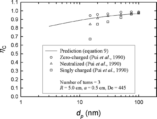
shows a comparison of nanoparticle penetration efficiency through a three-turn coil between the prediction by Equation (Equation9) and the experimental data of CitationPui et al. (1990), who generated submicron particles by spraying NaCl solution of 0.05, 0.5, or 10% volume concentration using a Collison atomizer and classified polydisperse aerosol with a differential mobility analyzer (DMA, TSI Model 3702). They measured the penetration efficiencies of zero-charged, neutralized, and singly charged particles through a three-turn coil made of glass. The dimensions of three-turn coil were R = 5.0 cm and a = 0.5 cm. The aerosol flow rate was 10.0 L/min. The resulting Dean number was approximately 445. For the prediction of penetration efficiency through the three-turn coil, the flow residence time (t) was calculated based on total length, or L = 3 × (2 π R). As shown in , Equation (Equation9) underestimates the penetration efficiencies of zero-charged particles, but with a reasonably small difference. In the case of neutralized particles, the predicted penetration efficiencies agree very well with CitationPui et al. (1990) for d p > 15 nm. This might be because the Equation (Equation9), in the present study, was derived from the penetration efficiencies of neutralized particles with equilibrium charge distribution. The data points of singly charged particles deviate relatively much from the predicted penetration efficiency curve.
FIG. 7 Comparison of nanoparticle penetration efficiency through a three-turn coil between the prediction by Equation (Equation9) and the experimental data of CitationPui et al. (1990).
4. CONCLUSIONS AND DISCUSSION
It is assumed that the nanoparticle loss in coils is mainly caused by the Brownian diffusion and can be enhanced by the secondary flow. The non-dimensional parameter of Gormley and Kennedy, ξ, can describe the diffusional particle loss to tube wall when the flow proceeds only in axial direction. For the flows in coils, there exist radial and tangential velocities due to the pressure gradient caused by centrifugal force, which results in the development of secondary flow. The particle loss by secondary flow can be described with the introduction of boundary layer thickness (δ). According to the core-and-boundary-layer concept of CitationMori and Nakayama (1965), average velocity of secondary flow within the boundary layer is dependent upon δ. The average velocity is related to the possibility for the particles to diffuse to tube wall, and then can affect the enhancement of diffusional particle loss by the secondary flow. As a result, a new dimensionless parameter for explaining the particle loss in coils, ζ, was defined as the product of the boundary layer thickness of secondary flow and the Gormley and Kennedy's parameter of diffusivity, namely, ζ = δ × ξ. It was successful to obtain an empirical equation of the nanoparticle penetration efficiency through coils in laminar flow regime, as a function of this new coil parameter, ζ.
In order for the boundary layer theory to be valid, the flow Reynolds number should be much larger than 1. According to Equation (Equation7), the boundary layer thickness of the secondary flow, δ, is approximately 1, when the Dean number is 20. It is physically not possible for the boundary layer thickness to be equal to or greater than 1. The prediction of penetration efficiency through coils using Equations (Equation8) and (Equation9) can therefore be applicable for the flow Reynolds number much larger than 1 and the Dean number larger than 20, and might deviate much from the real penetration efficiency as the Dean number approaches 20.
Once a flow passing through a coil is fully developed, the velocity profile of the secondary flow remains unchanged unless the curvature ratio of coil is varied. For a multi-turn coil, the secondary flow is developing only at the entry of the first turn and fully developed afterwards. Moreover, the particle loss in coils is determined only by t for how long the particles undergo the secondary flow, if δ, D, and a are fixed, from the definition of ζ in Equation (Equation8). It is therefore valid to think of the multi-turn coil as a single transportation line instead of a series of single-turn coils.
For the prediction of nanoparticle penetration efficiencies through the three-turn coil in , a constant diffusion coefficient (D) and a relatively small pressure drop across the coil were assumed. The problem, however, is that D is pressure-dependent due to the slip correction as can be checked by Equation (Equation3). It is therefore questionable if Equation (Equation9) can be applied for a coil of, say, ten or twenty turns, because the pressure at the entry of the coil has to be much higher than the outlet pressure, where the assumption of constant D throughout the multi-turn coil may fail. The secondary flow is developing at the most part of a bend, while the importance of the length of secondary flow development can be reduced and/or ignored for the single- and multi-turn coils. It is therefore needed to investigate how well Equation (Equation9) works to predict the nanoparticle penetration efficiency through a 90° bend.
The authors wish to thank Dr. Christof Asbach and Dr. Jing Wang for their helpful comments and discussion.
REFERENCES
- Bartz , H. , Fissan , H. and Liu , B. Y. H. 1987 . A New Generator for Ultrafine Aerosols Below 10 nm . Aerosol Sci. Technol. , 6 : 163 – 171 . [CSA]
- Chen , D. -R. , Pui , D. Y. H. , Hummes , D. , Fissan , H. , Quant , F. R. and Sem , G. J. 1998 . Design and Evaluation of a Nanometer Aerosol Differential Mobility Analyzer (Nano-DMA) . J. Aerosol Sci. , 29 : 497 – 509 . [CROSSREF] [CSA]
- Cheng , Y. S. and Wang , C. S. 1981 . Motion of Particles in Bends of Circular Pipes . Atmos. Environ. , 15 : 301 – 306 . [CROSSREF] [CSA]
- Fuchs , N. A. 1963 . On the Stationary Charge Distribution on Aerosol Particles in a Bipolar Ionic Atmosphere . Geofis. Pura Appl. , 56 : 185 – 193 . [CROSSREF] [CSA]
- Gormley , P. G. and Kennedy , M. 1949 . Diffusion from a Stream Flowing Through a Cylindrical Tube . Proc. Royal Irish Acad. , 52 : 163 – 169 . [CSA]
- Han , H. -S. , Chen , D. -R. , Pui , D. Y. H. and Anderson , B. E. 2000 . A Nanometer Aerosol Size Analyzer (nASA) for Rapid Measurement of High-Concentration Size Distributions . J. Nanopart. Res. , 2 : 43 – 52 . [CROSSREF] [CSA]
- Hinds , W. C. 1999 . Aerosol Technology-Properties, Behavior, and Measurement of Airborne Particles., , 2nd edition , New York : John Wiley & Sons, Inc. .
- Ito , H. 1959 . Friction Factors for Turbulent Flow in Curved Pipes . J. Basic Eng. , 81 : 123 – 134 . [CSA]
- Mercer , T. T. and Mercer , R. L. 1970 . Diffusional Deposition from a Fluid Flowing Radially Between Concentric, Parallel, Circular Plates . J. Aerosol Sci. , 1 : 279 – 285 . [CROSSREF] [CSA]
- Mori , Y. and Nakayama , W. 1965 . Study on Forced Convective Heat Transfer in Curved Pipes (1st Report, Laminar Region) . Int. J. Heat Mass Transfer , 8 : 67 – 82 . [CROSSREF] [CSA]
- Possanzini , M. , Febo , A. and Liberti , A. 1983 . New Design of a High-Performance Denuder for the Sampling of Atmospheric Pollutants . Atmos. Environ. , 17 : 2605 – 2610 . [CROSSREF] [CSA]
- Pui , D. Y. H. , Romay-Novas , F. and Liu , B. Y. H. 1987 . Experimental Study of Particle Deposition in Bends of Circular Cross Section . Aerosol Sci. Technol. , 7 : 301 – 315 . [CSA]
- Pui , D. Y. H. , Lewis , C. W. , Tsai , C. -J. and Liu , B. Y. H. 1990 . A Compact Coiled Denuder for Atmospheric Sampling . Environ. Sci. Technol. , 24 : 307 – 312 . [CROSSREF] [CSA]
- Sato , S. , Chen , D. -R. and Pui , D. Y. H. 2003 . Particle Transport at Low Pressure: Deposition in Bends of a Circular Cross-Section . Aerosol Sci. Technol. , 37 : 770 – 779 . [CROSSREF] [CSA]
- Scheibel , H. G. and Porstendörfer , J. 1983 . Generation of Monodisperse Ag- and NaCl-Aerosols with Particle Diameters between 2 and 300 nm . J. Aerosol Sci. , 14 : 113 – 126 . [CROSSREF] [CSA]
- Soh , W. Y. and Berger , S. A. 1984 . Laminar Entrance Flow in a Curved Pipe . J. Fluid Mech. , 148 : 109 – 135 . [CSA]
- Tan , C. W. and Thomas , J. W. 1972 . Aerosol Penetration Through a Parallel-Plate Diffusion Battery . J. Aerosol Sci. , 3 : 39 – 43 . [CROSSREF] [CSA]
- Tsai , C. -J. and Pui , D. Y. H. 1990 . Numerical Study of Particle Deposition in Bends of a Circular Cross-Section—Laminar Flow Regime . Aerosol Sci. Technol. , 12 : 813 – 831 . [CSA]
- Wang , J. , Flagan , R. C. and Seinfeld , J. H. 2002 . Diffusional Losses in Particle Sampling Systems Containing Bends and Elbows . J. Aerosol Sci. , 33 : 843 – 857 . [CROSSREF] [CSA]
- Wiedensohler , A. 1988 . An Approximation of the Bipolar Charge Distribution for Particles in the Submicron Size Range . J. Aerosol Sci. , 19 : 387 – 389 . [CROSSREF] [CSA]
