Historically, obtaining quantitative chemical information using laser desorption ionization mass spectrometry for analyzing individual aerosol particles has been quite challenging. This is due in large part to fluctuations in the absolute ion signals resulting from inhomogeneities in the laser beam profile, as well as chemical matrix effects. Progress has been made in quantifying atomic species using high laser powers, but very few studies have been performed quantifying molecular species. In this study, promising results are obtained using a new approach to measure the fraction of organic carbon (OC) associated with elemental carbon (EC) in aerosol particles using single particle laser desorption ionization. A tandem differential mobility analyzer (TDMA) is used to generate OC/EC particles by size selecting EC particles of a given mobility diameter and then coating them with known thicknesses of OC measured using a second DMA. The mass spectra of the OC/EC particles exiting the second DMA are measured using an ultrafine aerosol time-of-flight mass spectrometer (UF-ATOFMS). A calibration curve is produced with a linear correlation (R2 = 0.98) over the range of OC/EC ion intensity ratios observed in source and ambient studies. Importantly, the OC/EC values measured in ambient field tests with the UF-ATOFMS show a linear correlation (R2 = 0.69) with OC/EC mass ratios obtained using semi-continuous filter based thermo-optical measurements. The calibration procedure established herein represents a significant step toward quantification of OC and EC in sub-micron ambient particles using laser desorption ionization mass spectrometry.
INTRODUCTION
Carbonaceous species contribute up to as much as 90% of the total PM2.5 particulate mass (CitationHerner et al. 2005; CitationLim and Turpin 2002; CitationZheng et al. 2002). Carbonaceous aerosols are traditionally sub-divided into two major fractions: elemental carbon (EC) and organic carbon (OC). Ambient carbonaceous aerosols range from pure OC and EC to a mixture of the two (CitationBurtscher et al. 1998; CitationKatrinak et al. 1992; CitationKwon et al. 2003; CitationMader and Pankow 2002). EC is formed from the incomplete combustion of organic species and originates from sources such as vehicle emissions, industrial emissions, and biomass burning. The EC fraction is often referred to as soot or black carbon due to the absorbing properties in the atmosphere (CitationHorvath 1993). OC is also released from vehicles, biomass burning, as well as biogenic sources. OC can be directly emitted into the atmosphere in the particle (primary organic aerosol) or the gas phase. OC species in the gas phase often undergo oxidation reactions that lead to the formation of secondary organic aerosol (SOA) (CitationOdum et al. 1997). SOA will form by homogeneous or heterogeneous nucleation on preexisting seed aerosols. Homogeneous nucleation is less common in urban environments due to the presence of significant numbers of “seed” aerosols. The relative fraction of EC and OC in particles vary as a function of the particle source (CitationKleeman et al. 2000) and change as particles age (CitationLiousse et al. 1995).
EC particles absorb incoming solar radiation leading to an increase in radiative forcing (direct effect) (CitationPenner et al. 1998). The mixing state of EC strongly influences the overall absorbing properties of EC particles (CitationJacobson 2001). The addition of an organic coating to an EC core has been shown to increase the absorption coefficient of the aerosol by up to 35% (CitationSchnaiter et al. 2003). Furthermore, EC, which is normally considered a hydrophobic aerosol species, often undergoes aging processes that result in increased hydrophilic properties via direct oxidation or coating with polar organic species (CitationZuberi et al. 2005). This change in the surface properties of EC particles increases their ability to act as cloud condensation nuclei (CCN), enhancing their indirect effect on climate (CitationNovakov and Penner 1993; CitationSaxena et al. 1995; CitationWeingartner et al. 1997). A better understanding of the level of mixing between EC and OC in ambient particles is needed to quantitatively assess the overall impact carbonaceous aerosols have on climate change.
Single particle mass spectrometry is a tool that can be used to directly probe the particle mixing state of laboratory generated soot and ambient particles (CitationGuazzotti et al. 2001b; CitationKirchner et al. 2003; CitationWhiteaker et al. 2002). The ATOFMS measures the aerodynamic diameter of individual particles and then uses laser desorption/ionization coupled with a dual polarity time-of-flight mass spectrometer to obtain positive and negative ion information on individual particles (CitationGard et al. 1997; CitationPrather et al. 1994). ATOFMS has been used in a number of atmospheric measurement campaigns and provides complementary information on aerosol chemistry and particle variability in the environment (CitationBeddows et al. 2004; CitationGuazzotti et al. 2001a). Single particle mass spectrometers such as ATOFMS provide information on the number concentrations of chemically distinct particle types, showing how these concentrations change over time (CitationLiu et al. 2003; CitationPastor et al. 2003).
It has been questioned as to whether laser desorption ionization (LDI) analysis of aerosols can be used to quantitatively assess the amounts of specific chemical species such as OC and EC in ambient particles. Achieving quantitative chemical information on aerosols using ion intensities produced by LDI has had limited success to date (CitationBhave et al. 2002; CitationFergenson et al. 2001; CitationGross et al. 2000; CitationLee et al. 2005; CitationSmith et al. 2002; CitationWoods et al. 2001). The most promising quantitative results have been obtained for LDI processes producing atomic ions (CitationLee et al. 2005; CitationReents and Ge 2000). However, more detailed information on the organic species or the source producing the species contained within a particle is lost when the particle is ablated and ionized to the atomic level. Indeed, determining the relative fractions of chemical species within a single particle is quite challenging due to differences in the laser pulse energy encountered by each particle during the ionization process. Absolute ion area has been shown to fluctuate by as much as 59% from monodisperse aerosol particles with the same composition (CitationGross et al. 2000). These differences in ionization between chemically similar particles have been attributed to an inhomogeneous laser beam profile (CitationWenzel and Prather 2004). Furthermore, matrix effects between dissimilar particles can also produce differences in the ion abundances. However, as shown herein, averaging the mass spectra of an ensemble of particles of the same size with similar chemical composition reduces the effects of the shot-to-shot single particle ion signal fluctuations.
This article describes an initial effort to use the ratios of mass spectral ion signal intensities to establish OC/EC mass fractions in ambient carbonaceous aerosols using an ultrafine aerosol time-of-flight mass spectrometer (UF-ATOFMS). A key component of this study involves creating and characterizing the ion response to laboratory generated OC/EC particles using a tandem differential mobility analyzer (TDMA) (CitationRader and McMurry 1986) coupled with an ATOFMS. The resulting OC/EC values measured with an ATOFMS are compared to those obtained with a standard OC/EC thermo-optical method for carbonaceous particles sampled during vehicle source tests. Establishing correlations between ion signals and OC/EC mass fractions in particles represents a significant step in our ability to quantitatively assess the different chemical components in ambient aerosols using single particle mass spectrometry.
EXPERIMENTAL
A description of the UF-ATOFMS is given in detail elsewhere (CitationSu et al. 2004). Briefly, the UF-ATOFMS measures the vacuum aerodynamic diameter (dae) of particles between 50–1000 nm and a dual polarity mass spectrum for each individual particle.
Particle Generation
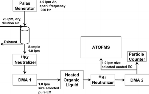
A schematic of the experimental set-up used for these experiments is shown in . Elemental carbon (EC) particles were generated using a spark discharge across graphite rods with a commercially available instrument (GfG 1000, Palas generator) (CitationHelsper et al. 1993; CitationRoth et al. 2004). A spark frequency of 200 Hz was used. Argon was used as a purge gas at a flow rate of 5.0 L min− 1. EC particles were further diluted downstream in a 1 L dilution chamber with approximately 25 L min− 1 of dry, purified (using activated carbon and Purafil adsorbents), and HEPA-filtered air. One L min− 1 of the diluted EC particle stream was pulled through a differential mobility analyzer (DMA-1) (TSI 3080), to select particles with a desired electrical mobility equivalent diameter (dme). The sheath flow for DMA-1 was set at 10 L min− 1. These size selected particles then passed through a 1.5 L cylindrical flask containing ∼200 mL 85-octane (regular) unleaded fuel at the bottom. Aerosols entered this flask approximately 3 inches above the liquid (within the headspace). The temperature of unleaded fuel was regulated using a heated water bath. Fresh unleaded fuel was used for each temperature run. Each experiment lasted approximately 15 minutes and no changes in the particle mass spectra occurred from beginning to end of any experiment. For analysis of EC particles with no organic coating, the particles passed through the same flask containing no unleaded fuel. Depending on the experiment, OC coated or uncoated EC particles were pulled through a second DMA (DMA-2), with a condensation particle counter attached to it. DMA-2 coupled to a CPC was used to obtain the electrical mobility size distribution of uncoated and coated EC particles. Sample flow through DMA-2 was 1 L min− 1 and the sheath flow was set at 10 L min− 1. Uncoated monodisperse EC particles could also be sent directly to the UF-ATOFMS for aerodynamic sizing and chemical analysis, bypassing DMA-2. DMA-2 was also used to size select EC particles coated with organic material at size of 100, 150, and 250 nm. These size selected OC coated aerosols were then sampled by the UF-ATOFMS for aerodynamic size and chemical analysis.
Figure 1 General measurement set-up. Pure EC aerosol flows from the Palas generator to a dilution chamber, a charge neutralizer, and then DMA-1 where they are size selected. Aerosols can be measured with UF-ATOFMS as pure EC or OC coating EC in a temperature regulated flask containing gasoline. Uncoated and coated aerosol size distributions are measured with DMA-2 and a condensation particle counter. For coated aerosols, DMA-2 size selects coated aerosols, which are sent to the UF-ATOFMS for size (vacuum aerodynamic diameter) and composition analysis.
Data Analysis
Approximately 500 dual ion mass spectra were obtained for each experiment. UF-ATOFMS data were imported into Matlab Version 6.1.0.450 Release 12.1 (The MathWorks, Inc.) and analyzed using YAADA version 1.2 [http://www.yaada.org]. For each experiment, the set of mass spectra were converted into a relative area matrix. The relative area matrix represents the average of all mass spectra generated for each experiment. To create a relative area matrix, all ion peaks in each individual mass spectrum are first normalized to the most intense peak within the spectrum and then all of the normalized individual mass spectra are averaged.
Ambient Data Collection
UF-ATOFMS ambient field data were collected during field studies conducted at three locations: the I-5 Freeway (CitationToner et al. 2006a) in San Diego in 2004, as well as the cities of Boston in 2003, and Atlanta (CitationSu 2002) in 2002. Three vehicle source characterization data sets are also used in this study: diesel powered truck data (CitationShields et al. 2006) acquired in 2001, gasoline powered vehicle particle data (CitationSodeman et al. 2005) acquired in 2002, and diesel powered truck particle data (CitationToner et al. 2006b) acquired in 2003.
UF-ATOFMS and thermal-optical OC/EC comparison measurements were made during the Secondary Organic Aerosols in Riverside (SOAR) field campaign in Riverside, California, during July and August of 2005. A Sunset Labs OC EC monitor, which uses the National Institute for Occupational Safety and Health (NIOSH) method, was used for thermal-optical OC and EC mass analysis. The Sunset Labs instrument was operated to give one hour time resolution. The UF-ATOFMS was operated down stream of a multiple orifice uniform deposit impactor (MOUDI) which removed over 50% of particles greater then 450 nm (aerodynamic diameter). For UF-ATOFMS data analysis, only particles between 50 and 400 nm were analyzed.
RESULTS AND DISCUSSION
Uncoated and OC-Coated Electrical Mobility Size Distributions
To explore the feasibility of using EC and OC ion markers from an UF-ATOFMS to quantify the relative OC/EC mass fraction in particles, we begin by discussing the electrical mobility size distributions of uncoated EC and OC coated EC particles. This provides information on particle size and shape that is needed for accurate determination of particle mass as described below. A TDMA arrangement coupled with a flow tube where an organic liquid (gasoline) could be heated to different temperatures was used to add OC coatings to EC cores.
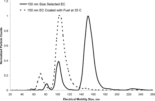
shows three different scans taken with a scanning mobility particle sizer (SMPS) for OC coated and uncoated EC particles. Each size distribution in has been normalized to the size bin with the largest number of particle counts to show how the relative size distribution of each curve changes during the coating process. shows the electrical mobility size distribution of 100 nm EC particles size selected from DMA-1 without an OC coating. The total particle concentration for uncoated EC particles was 80,000 particles/cm3. Uncoated EC particles showed a major peak at 106 nm. Other peaks at 71 nm and 57 nm are attributed to doubly and triply charged 106 nm EC particles respectively. A small peak at 157 nm is also observed. This peak at 157 nm is due to particles that were emitted from the first DMA at a mobility diameter of 100 nm that contained two charges (larger particles, with two charges), and became singly charged in the second neutralizer. A slight positive deviation in the expected SMPS size distribution was also observed for 110 nm polystyrene latex spheres which showed a major peak at 113 nm. The peak at 106 nm in occurs at 106 nm instead of 100 nm most likely due to miscalibration of the DMA. shows the distribution of 100 nm size selected EC particles sent through a flask containing unleaded fuel heated to 75°C. The total particle concentration for EC particles coated with fuel vapor at 75°C was 11,000 particles/cm3. Note that the major peak observed for the uncoated particles at 106 nm is shifted down to 76 nm upon coating, suggesting the 100 nm EC particles have collapsed. Using Scanning Electron Microscopy (SEM) and SMPS, spark discharge EC and diesel generated EC has been observed to collapse (rearrange) into a more spherical particle when coated with OC (CitationSaathoff et al. 2003; CitationSchnaiter et al. 2003; CitationWeingartner et al. 1997). Because these particles went through a aerosol neutralizer prior to the SMPS the peak observed at 76 nm is mostly singly charged (CitationWiedensohler 1988). The plots show a broad distribution of particle sizes. This wide distribution corresponds to EC particles coated with varying amounts of OC, as well as EC particles with a distribution of shapes. It should be noted that particles were not observed during blank (no EC particles) runs with fuel heated to 75°C. This indicates that self nucleation of the fuel vapor is not occurring and there is no outside contamination from other particles. Finally, the size distribution of particles coated with unleaded fuel heated to 55°C is shown. The total particle concentration for EC particles coated with fuel vapor at 55°C was 55,000 particles/cm3. At 55°C, the relative concentration of coated particles (electrical mobility diameter larger then 76 nm) was lower than at 75°C because less organic vapor is available to condense on the EC particles. To explore EC particle collapse further, a coating experiment was performed to lightly coat 150 nm EC particles with fuel vapor at 35°C. shows the SMPS scan of uncoated 150 nm size selected spark discharge EC particles and 150 nm size selected spark discharge EC particles sent through unleaded fuel vapor (at 35°C). shows that 150 nm EC particles collapsed to an electrical mobility diameter of 100 nm and very few particles grew to larger sizes. OC-coated EC particles in maintained a very monodisperse size profile after collapse. Again, because an aerosol neutralizer was used, the major peak should not be from doubly charged particles (CitationWiedensohler 1988). It should be noted that the fuel-coated particles in entered a flow tube downstream of the flask containing the unleaded fuel and were diluted 5-fold with nitrogen. The lack of heavily coated particles for the 35°C experiment is attributed to dilution of the coated particles with nitrogen and a lower amount of OC vapor due to a lower (35°C) bath temperature. Diluting the particle stream after coating shifts the OC gas-particle equilibrium, producing more OC in the gas phase.
Figure 2 Scanning mobility particle size distributions for 100 nm size selected uncoated EC (solid curve), 100nm size selected EC coated with OC from a 75°C unleaded fuel sample (dotted curve), and 100 nm size selected EC coated with OC using a 55°C unleaded fuel sample (dashed curve). Each curve has been normalized to the size bin with the greatest number of particles to allow a better visual comparison of the size distribution profile between each curve.
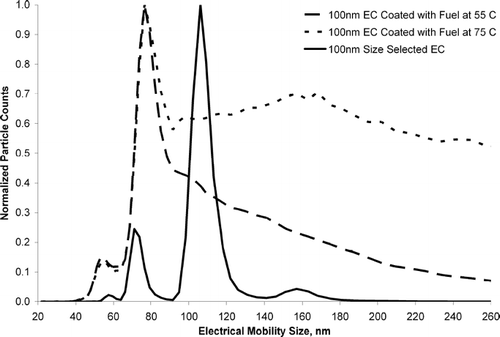
Figure 3 SMPS scan of uncoated pure spark discharge soot, size selected at 150 nm (solid curve), and 150 nm EC passed through a cylinder of fuel at 35°C (dotted curve). Each curve has been normalized to the size bin with the largest number of particles to allow a better visual comparison of the size distribution profile between each curve.
Calculation of EC and OC Mass
Using the UF-ATOFMS, the average vacuum aerodynamic diameter (dae) was determined for each experiment by averaging all diameters for a given experiment together. A 95% confidence interval was used to obtain high and low values for the average aerodynamic size. Using a 5% range in the electrical mobility size and the 95% confidence interval range of aerodynamic size, the mass of EC and OC on uncoated and coated particles are calculated two different ways as described below.
Because pure spark discharge EC particles have very irregular shapes, using dme or dae as the true physical diameter for uncoated EC is not entirely accurate. However, the volume equivalent diameter (dve), which is the volume of a sphere that has the same volume as the irregular shaped particle, can be calculated using the equation for the electrical mobility, Z, of irregularly shaped particles (CitationKasper 1982). This is given as
where n is the number of elementary charges on each particle, e is the charge of an electron, Cme and Cve are the Cunningham slip correction factors for dme and dve, respectively, μ is the absolute viscosity of air and χ is the dynamic shape factor. Non-spherical particles will have an electrical mobility that is related to a volume equivalent particle diameter through the dynamic shape factor, χ. Dynamic shape factors have been calculated for EC particles (CitationPark et al. 2004; CitationSlowik et al. 2004). Shape factors for 150 nm (dme) propane generated EC particles from Slowik et al. ranged between 1.5 and 2.4. CitationPark et al. (2004) found shape factors vary between 1.1 and 2.1 for diesel EC as a function of electrical mobility size between 50 and 200 nm, respectively. To calculate dve here, we assume a dynamic shape factor of 1.8, which is a reasonable assumption based upon published values for EC agglomerates. gives the experiment type, electrical mobility diameter before entering the UF-ATOFMS, the average vacuum aerodynamic diameter for each experiment and a calculated range of volume equivalent diameters. The range of estimated volume equivalent diameters shown in is based on using a 5% error in the DMA resolution. shows pure spark discharge EC particles with electrical mobility diameters between 95–105, 114–126, and 142–158 nm have volume equivalent diameters between 68–75, 81–89, and 100–110 nm, respectively. It should be noted the estimated volume equivalent diameters are similar to the collapsed particle diameter observed in and . As discussed by CitationDeCarlo (2004), particles in a compact aggregate state, such as OC coated EC, have more spherical morphologies and shape factors closer to 1. Therefore we assume a shape factor for collapsed OC coated EC particles of 1.0. When one assumes a shape factor of 1, then mobility diameter will be equal to the volume equivalent diameter. The values for dve are therefore reported as dme (+/−5%) in for coated particles.
TABLE 1 Average aerodynamic equivalent diameter for each mobility equivalent diameter selected for each experiment
An OC-coated EC particle can be thought of as a collapsed EC sphere surrounded by an OC shell. Using dve, the volume of both the pure EC core and the total particle volume for a coated particle can be calculated. Subtracting the EC core volume from the total coated particle volume leaves the volume of the shell, which is attributed to OC. By assuming bulk material densities for EC and OC, the masses of the EC core and the OC shell can be determined. Values for the total particle mass, OC mass, and OC mass fraction for each of the experiments are given in . Column 1 lists the experiment name and the electrical mobility diameter before entering the ATOFMS. Column 2 gives the range of particle masses calculated using a range of possible material densities and a 5% range in the electrical mobility diameter for each experiment. The EC mass given in was calculated using a density range for EC between 1.6–2.0 g/cm3, which encompasses the material density range reported for flame generated soot (CitationChoi et al. 1995). We assume the material density of spark discharge EC is within the range for flame soot. OC mass given in was obtained using values of 0.65–0.85 g/cm3 for the density of gasoline based on the value provided by the National Institute of Standards and Technology (NIST) (0.7–0.8 g/cm3). Columns 3 and 4 show the calculated ranges for the mass of OC and mass fraction of OC, respectively.
TABLE 2 Calculated particle mass and OC mass from assumed material density
A second method for estimating the mass of the different uncoated and coated particles involves determining the effective density using the vacuum aerodynamic diameter and electrical mobility diameter. By multiplying the effective density and the volume (volume based on mobility diameter), particle mass is obtained. Using dme and dae the effective density for the particles can be calculated using the equation
where dae is the vacuum aerodynamic diameter, dme is the electrical mobility diameter, ρ eff is the effective density, and ρo is the unit density (1.0 g/cm3) (CitationDeCarlo et al. 2004; CitationJimenez et al. 2003). shows a plot of the calculated effective densities for uncoated EC particles versus dme compared with values reported by CitationPark et al. (2003) for diesel soot particles of the same electrical mobility size. The vertical error bars in were generated from effective densities calculated using a 5% range in the electrical mobility diameter and a 95% confidence interval of the mean vacuum aerodynamic diameter. It is clear from that the effective densities calculated here are systematically higher but in good agreement with those reported by Park et al. This density difference likely reflects the difference in soot structure that has been observed for spark discharge and diesel engine EC (CitationKirchner et al. 2003; CitationSaathoff et al. 2003; CitationSchnaiter et al. 2003). Using the effective density and the electrical mobility diameter, the OC/EC mass fractions for the particles were determined. shows the total mass per particle, the mass of OC associated with coated particles, and the OC mass fraction. Column 1 lists the experiment name and the electrical mobility diameter measured before entering the ATOFMS. Column 2 gives the total particle mass for each experiment. The mass of OC given in Column 3 was calculated by subtracting the mass of the EC core from the total particle mass. A comparison of the results presented in and shows the mass fractions of OC calculated using the two different approaches agree to within 10%.
Figure 4 Spark discharge soot effective densities calculated from DMA and UF-ATOFMS data plotted versus particle mobility equivalent diameter. Vertical error bars represent the standard deviation in the effective density generated from using aerodynamic diameters within a 95% confidence interval and a 5% range in the chosen mobility diameter. For comparison, values reported for diesel soot by CitationPark et al. (2003) are also shown.
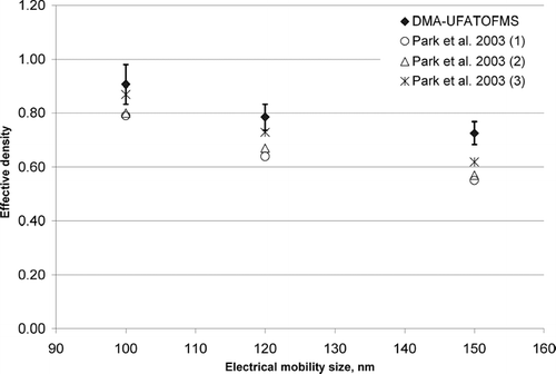
TABLE 3 Calculated particle mass and OC mass from effective density
Determining OC and EC Mass Fractions from Mass Spectral Ion Intensities
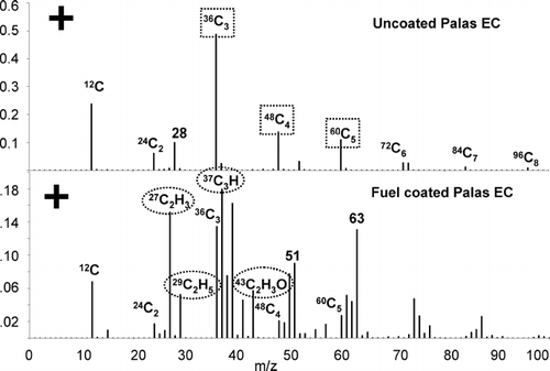
As stated earlier, the major goal of this work is to establish a correlation between the intensities of EC and OC ions in single particle mass spectra with the actual OC/EC mass fractions for a collection of carbonaceous particles. This correlation results in a calibration curve that quantitatively relates ion intensities in source and ambient studies with OC/EC mass fractions. shows the average positive ion relative area matrix for 140 uncoated spark discharge EC particles and 98 OC coated spark discharge EC particles. A description of how an area matrix is created is given in the Methods section. The two particle types shown in are readily distinguishable. The uncoated EC area matrix is dominated by positive ion carbon cluster peaks 12C1 to 96C8 attributed to EC. A peak at m/z +28 is also observed which is attributed to silicon (CitationWentzel et al. 2003). The OC coated spark discharge EC in shows many peaks attributed to EC, however, it also contains OC peaks at m/z 27 (CNH+, C2H3 +), 29 (C2H5 +), 37 (C3H+), 39 (C3H3 +), 43 (C3H7 +, C2H3O+), 51 (C4H3 +), and 63 (C5H3 +). The ions listed in parentheses are possible ion peak assignments based on previous lab studies by our group and electron impact spectra of organic compounds compiled by others (CitationMcLafferty 1980). In general, as a particle grows in size, the OC peak intensities increase while the EC peaks are reduced in intensity, suggesting the addition of OC to EC changes the matrix and the overall response of the instrument to EC ion signals. The ATOFMS shows a higher sensitivity to fresh EC particles with higher absolute signal intensities measured for fresh uncoated EC particles. To establish a correlation between OC/EC intensity ratios and the mass of OC and EC in particles, the ion markers shown in attributed to OC (m/z 27+, 29+, 37+, 43+) and EC (m/z 36+, 48+, 60+) are used as they are commonly observed in ambient particles. Other ions for OC such as m/z 39+, 41+, and 51+ were not chosen because ions from potassium and vanadium are also observed at these m/z in ambient particles. More then one ion was chosen because individual ion areas fluctuate much more than the sum of multiple ions. As mentioned, large shot-to-shot ion intensity variations are observed in most single particle mass spectrometers. However, the signals tend to increase and decrease in the same proportion (CitationGross et al. 2000), and thus by using the ratio of OC to EC ion intensities to calculate the OC/EC mass fractions, the effect of the ion signal fluctuations on quantification is minimized.
Figure 5 Average area matrix from approximately 140 uncoated spark discharge soot particles and 98 fuel coated spark discharge soot particles. Squares indicate ion markers used for EC, and ovals for OC.
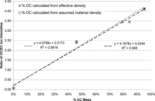
shows a graph of the mass percentage of OC using material densities (open circles) as well as those obtained from a calculation of effective density (asterisks) versus the OC/EC mass spectral ion intensity ratios. The OC mass percentages and error bar values correspond to data from the last column of and . A linear correlation exists between the OC/EC ion ratio and mass percentage of OC calculated from assumed material densities with an R2 value of 0.98. shows a point for an uncoated 100 nm (dme) spark discharge generated EC particle, which falls almost at zero (OC/EC ratio) as expected. A linear correlation with an R2 value of 0.99 is shown in for the percent of OC mass calculated from effective densities and the OC/EC ratios. It should be noted these linear correlations do not imply the response of the UF-ATOFMS is linear with respect to OC and EC concentration; we are plotting a ratio versus a percentage which would diverge if there was a linear instrument response. These correlations show it is possible to calibrate the ATOFMS using ion intensity ratios and obtain quantitative chemical information for particles with similar chemical matrices. It is important to note that a break at 1 μ m separates particles composed of predominately organic versus inorganic matrices (CitationNoble and Prather 1996; CitationPastor et al. 2003). Thus this calibration curve will most likely be most effective for sub-μ m particles since these will have similar carbonaceous matrices and thus similar ion signal responses.
Figure 6 Calculated faction of OC contained in each particle is plotted versus the OC/EC ratio from specific ion signals. Open circles represent OC mass calculated from an estimation of material densities. Error bars for the open circles were generated using a range of assumed material densities and a 5% range in the electrical mobility diameter. Asterisks represent OC mass calculated from the measurement of effective density. Vertical error bars for the asterisks indicate the standard deviation in the %OC mass generated from using the mean aerodynamic diameters within a 95% confidence interval and a 5% range in the mobility diameter. The points at 0% OC mass represent uncoated pure EC.
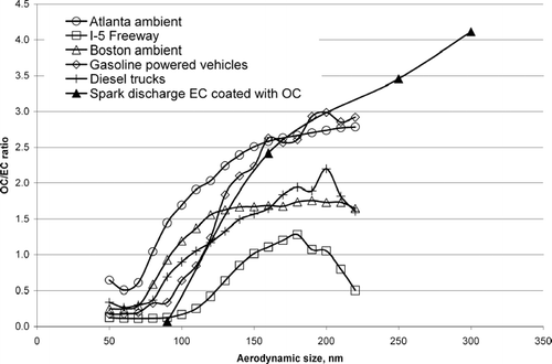
To determine whether laboratory generated OC-EC particles produce OC/EC ion intensity ratios that fall in the range of those measured for ambient particles in the same size range, the OC/EC ion intensity ratios for a number of source and ambient study particles were calculated. shows a plot of the OC/EC ion intensity ratio versus the vacuum aerodynamic size for the laboratory generated OC-EC particles, three ambient locations (San Diego-Freeway, Boston, Atlanta) and two vehicle dynamometer studies (gasoline powered vehicles, diesel powered trucks). As shown, the OC/EC ratios for the ambient and vehicle data sets lie within the range of OC/EC ion intensity ratios observed for the laboratory generated OC-EC particles presented here. This suggests the OC/EC ratios calculated using laboratory generated OC-EC particle standards indeed have atmospheric relevance and can be used to estimate the fractions of OC and EC in ambient particles with similar chemical composition and size.
Figure 7 The OC/EC ratio is plotted versus vacuum aerodynamic size for particles analyzed at three ambient locations (I-5 Freeway, Boston, Atlanta) and two vehicle dynamometer studies (gasoline powered vehicles, diesel powered trucks). For comparison, the OC/EC ratio for spark discharge EC coated with different amounts of OC is also plotted versus its average aerodynamic size.
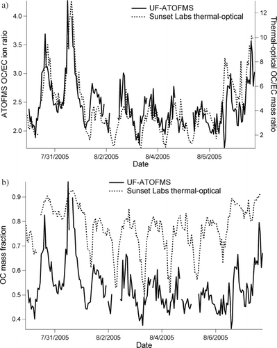
To further explore the significance of using OC/EC ion intensity ratios to estimate the OC/EC mass fraction in ambient particles, a comparison of the UF-ATOFMS OC/EC ion intensity ratios was made to the OC/EC mass ratios measured with a Sunset Lab semi-continuous thermal/optical method. exhibits eight days of ambient data taken from July 30–August 7, 2005 in Riverside, California. The UF-ATOFMS data contains all particles analyzed between 50–400 nm and the thermal-optical data is for all particles < 2.5 μ m. In , the left y-axis is UF-ATOFMS OC/EC ion ratio and the right y-axis thermal-optical OC/EC mass ratio with date given along the x-axis. Both the UF-ATOFMS and thermal-optical instrument show daily fluctuations in their respective OC/EC ratio with very comparable relative intensity between each method. The correlation between the UF-ATOFMS and thermal-optical data in yields an R2 = 0.69. This shows that a change in the UF-ATOFMS OC/EC ion ratio for ambient particles reflects changes in the OC/EC mass ratio measured with the thermal-optical method. shows UF-ATOFMS ambient data from Riverside calibrated using the curve from to estimate the OC mass fraction. Also shown in is the thermal-optical OC mass fraction. Overall, shows daily fluctuations in the OC mass fraction are captured by both techniques and there is approximately a 20% difference between them. It should be pointed out that comparisons between similar thermal-optical techniques differing in temperature protocol or optical correction technique (thermal optical reflectance [TOR] versus thermal optical transmission [TOT]) have shown errors for estimating amount of EC or OC of more then 40% (CitationArhami et al. 2006; CitationChow et al. 2001, Citation2004, Citation2005a, Citation2005b; CitationSchauer et al. 2003). The NIOSH thermal-optical TOT protocol used here has been shown to measure half the amount of EC as measured using the IMPROVE method (CitationChow et al. 2001). Therefore, this comparison of the ATOFMS data with thermal-optical data, two techniques which rely on very different operating principles, is quite good. One other reason the ATOFMS underestimates the amount of OC relative to EC could be the UF-ATOFMS used for this study only sampled particles up to 400 nm, whereas the thermal-optical instrument measured particles up to 2.5μm. Particles in Riverside grow in size throughout the day from condensation of semi-volatile organics; therefore the larger size particles sampled by the thermal-optical method likely have a larger OC mass fraction. It is important to remember here that the thermal-optical method produces operationally defined values of EC and OC, whereas the ATOFMS is based on actual structural differences of EC and OC leading to different ion patterns in the mass spectra. In future studies, examining periods where the ATOFMS agrees or disagrees with the EC/OC mass concentration values may yield insight into the most appropriate operating conditions and protocols to be used by these thermal-optical instruments.
Figure 8 Ambient particle measurements taken during SOAR field campaign in Riverside, California, July–August of 2005. (a) The UF-ATOFMS OC/EC ion intensity ratio is plotted on the left y-axis and semi-continuous thermal optical OC/EC mass ratio on the right y-axis, with date given along the x-axis. (b) The OC mass fraction estimated using UF-ATOFMS (using calibration curve given in ) and OC mass fraction measured using thermal optical OC EC instrument is given on the y-axis with date given along x-axis.
CONCLUSIONS
In these experiments, EC particles of known size were coated with OC species from unleaded fuel vapor to create standard particles with different OC/EC mass fractions. The OC/EC mass fractions were determined using two separate approaches; first, assumptions were made about the shape and density of the particles based on literature values, and second, by calculating the effective densities of particles using the measured vacuum aerodynamic (UF-ATOFMS) and electrical mobility diameters (SMPS). Effective densities of pure spark discharge EC determined in these experiments are within 20% of values reported for diesel EC with the same mobility diameters. Using the two estimation methods for EC and OC mass, the OC/EC mass fraction as a function of particle size was determined. A calibration curve was created by plotting OC/EC ion intensity ratios against the calculated mass fractions of OC estimated from the two different methods. Strong linear correlations exist between the OC/EC ion ratio and the mass percentage of OC, estimated from assumed material densities (R2 = 0.98) and the measured effective density (R2 = 0.99). Both OC/EC mass correlations are within the range of uncertainties of each other.
The OC/EC ion intensity ratios derived from laboratory generated OC-EC standard particles compared well with particles in the same size range measured in multiple ambient and source data sets. Furthermore, the OC/EC values measured with the UF-ATOFMS showed a strong correlation with OC/EC values simultaneously measured for ambient data using traditional thermal-optical methods. Ambient OC mass fractions measured here were within ∼ 20% of those measured using a traditional thermal-optical technique and showed similar daily fluctuations. Using UF-ATOFMS, obtaining quantitative information regarding the OC/EC mass fractions in ambient particles with similar size and chemical composition appears to be quite feasible for carbonaceous particles.
With the recent interest in moving beyond mass measurements of atmospheric aerosols, there is a major need for methods which can generate particles that can be used for instrument calibration. The method used herein to generate OC/EC particles could be used for characterizing other instruments besides ATOFMS. For example, laboratory studies could be performed using these particles with known OC and EC mass concentrations to better understand observed differences in responses between similar methodologies such as the IMPROVE or NIOSH thermo-optical methods (CitationSchauer et al. 2003). This study shows it is possible to generate particles with similar composition to ambient particles that can be used to perform laboratory calibrations. A calibration curve can be used to relate the measured relative ion intensities in the mass spectra of unknown ambient particles to the relative amounts of specific species in/on ambient particles. The next step will be to perform further lab studies comparing calibration curves generated with EC coated with different classes of organic species. The response of such calibration curves to different organic material will yield information on the uncertainties of this approach. Furthermore, ATOFMS data will be compared with traditional thermal-optical methods, as well as other methods for measuring EC and OC, in future ambient field and source studies to further test the robustness of this procedure. Information regarding the relative amount of OC on EC particles will be critical to assessing the roles of these species in climate change and human health.
We would like to thank Professor Günter Oberdörster from University of Rochester for allowing us to use his EC spark discharge generator. James Schauer and Dave Snyder from University of Wisconsin-Madison generously collected, processed and made available the SOAR thermal-optical OC EC data. Ambient and vehicle emissions ATOFMS data was collected and made available from the generosity of the following people: Steve Toner, David Sodeman, Laura Shields, Yongxuan Su, Michelle Sipin, and Xueying Qin. This work was carried out with the support of the Environmental Protection Agency PM center under grant # R827354.
Notes
a Calculated based on an assumed shape factor of 1.8.
b OC coated EC particles are assumed to be spherical, so shape factor = 1 and dve = dme.
c Volume equivalent diameter was calculated based on a 5% range in the given mobility diameter.
a Assumed a density of 1.6–2.0 g/cm3, and a shape factor of 1.8.
b Assumed a density for OC of 0.65–0.85 g/cm3, and a shape factor of 1.0.
Related Research Data
REFERENCES
- Arhami , M. , Kuhn , T. , Fine , P. M. , Delfino , R. J. and Sioutas , C. 2006 . Effects of Sampling Artifacts and Operating Parameters on the Performance of a Semicontinuous Particulate Elemental Carbon/Organic Carbon Monitor . Environ. Sci. Technol. , 40 : 945 – 954 . [INFOTRIEVE] [CSA]
- Beddows , D. C. S. , Donovan , R. J. , Harrison , R. M. , Heal , M. R. , Kinnersley , R. P. , King , M. D. , Nicholson , D. H. and Thompson , K. C. 2004 . Correlations in the Chemical Composition of Rural Background atmospheric aerosol in the UK Determined in Real Time Using Time-of-Flight Mass Spectrometry . J. Environ. Monitor. , 6 : 124 – 133 . [CSA] [CROSSREF]
- Bhave , P. V. , Allen , J. O. , Morrical , B. D. , Fergenson , D. P. , Cass , G. R. and Prather , K. A. 2002 . A Field-Based Approach for Determining ATOFMS Instrument Sensitivities to Ammonium and Nitrate . Environ. Sci. Technol. , 36 : 4868 – 4879 . [INFOTRIEVE] [CSA] [CROSSREF]
- Burtscher , H. , Kunzel , S. and Huglin , C. 1998 . Characterization of Particles in Combustion Engine Exhaust . J. Aerosol Sci. , 29 : 389 – 396 . [CSA] [CROSSREF]
- Choi , M. Y. , Mulholland , G. W. , Hamins , A. and Kashiwagi , T. 1995 . Comparisons of The Soot Volume Fraction Using Gravimetric and Light Extinction Techniques . Combustion and Flame , 102 : 161 – 169 . [CSA] [CROSSREF]
- Chow , J. C. , Watson , J. G. , Chen , L. W. A. , Arnott , W. P. and Moosmuller , H. 2004 . Equivalence of Elemental Carbon by Thermal/Optical Reflectance and Transmittance with Different Temperature Protocols . Environ. Sci. Technol. , 38 : 4414 – 4422 . [INFOTRIEVE] [CSA] [CROSSREF]
- Chow , J. C. , Watson , J. G. , Chen , L. W. A. , Paredes-Miranda , G. , Chang , M. C. O. , Trimble , D. , Fung , K. K. , Zhang , H. and Yu , J. Z. 2005a . Refining Temperature Measures in Thermal/Optical Carbon Analysis . Atmos. Chem. Phys. , 5 : 2961 – 2972 . [CSA]
- Chow , J. C. , Watson , J. G. , Crow , D. , Lowenthal , D. H. and Merrifield , T. 2001 . Comparison of IMPROVE and NIOSH Carbon Measurements . Aerosol Sci. Technol. , 34 : 23 – 34 . [CSA]
- Chow , J. C. , Watson , J. G. , Louie , P. K. K. , Chen , L. W. A. and Sin , D. 2005b . Comparison of PM2.5 Carbon Measurement Methods in Hong Kong, China . Environ. Pollut. , 137 : 334 – 344 . [INFOTRIEVE] [CSA] [CROSSREF]
- DeCarlo , P. , Slowik , J. , Worsnop , D. , Davidovits , P. and Jimenez , J. 2004 . Particle Morphology and Density Characterization by Combined Mobility and Aerodynamic Diameter Measurements. Part 1: Theory . Aerosol Sci. Technol. , 38 : 1185 – 1205 . [CSA] [CROSSREF]
- Fergenson , D. P. , Song , X. H. , Ramadan , Z. , Allen , J. O. , Hughes , L. S. , Cass , G. R. , Hopke , P. K. and Prather , K. A. 2001 . Quantification of ATOFMS Data by Multivariate Methods . Anal. Chem. , 73 : 3535 – 3541 . [INFOTRIEVE] [CSA] [CROSSREF]
- Gard , E. , Mayer , J. E. , Morrical , B. D. , Dienes , T. , Fergenson , D. P. and Prather , K. A. 1997 . Real-Time Analysis of Individual Atmospheric Aerosol Particles: Design and Performance of a Portable ATOFMS . Anal. Chem. , 69 : 4083 – 4091 . [CSA] [CROSSREF]
- Gross , D. S. , Gaelli , M. E. , Silva , P. J. and Prather , K. A. 2000 . Relative Sensitivity Factors for Alkali Metal and Ammonium Cations in Single-Particle Aerosol Time-of-Flight Mass Spectra . Anal. Chem. , 72 : 416 – 422 . [INFOTRIEVE] [CSA] [CROSSREF]
- Guazzotti , S. A. , Coffee , K. R. and Prather , K. A. 2001a . Continuous Measurements of Size-Resolved Particle Chemistry during INDOEX-Intensive Field Phase 99 . J. Geophys. Res. [Atmospheres] , 106 : 28607 – 28627 . [CSA] [CROSSREF]
- Guazzotti , S. A. , Whiteaker , J. R. , Suess , D. , Coffee , K. R. and Prather , K. A. 2001b . Real-Time Measurements of the Chemical Composition of Size-Resolved Particles during a Santa Ana Wind Episode, California USA . Atmos. Environ. , 35 : 3229 – 3240 . [CSA] [CROSSREF]
- Helsper , C. , Moelter , W. , Loeffler , F. , Wadenpohl , C. , Kaufmann , S. and Wenninger , G. 1993 . Investigations of A New Aerosol Generator for the Production of Carbon Aggregate Particles . Atmos. Environ. Part A: General Topics , 27A : 1271 – 1275 . [CSA] [CROSSREF]
- Herner , J. D. , Aw , J. , Gao , O. , Chang , D. P. and Kleeman , M. J. 2005 . Size and Composition Distribution of Airborne Particulate Matter in Northern California: I—Particulates Mass, Carbon, and Water-Soluble Ions . J. Air & Waste Manag. Assoc. , 55 : 30 – 51 . [INFOTRIEVE] [CSA]
- Horvath , H. 1993 . Atmospheric Light-Absorption—A Review . Atmos. Environ. Part A-General Topics , 27 : 293 – 317 . [CSA] [CROSSREF]
- Jacobson , M. Z. 2001 . Strong Radiative Heating Due to the Mixing State of Black Carbon in Atmospheric Aerosols . Nature (London) , 409 : 695 – 697 . [CSA] [CROSSREF]
- Jimenez , J. L. , Bahreini , R. , Cocker , D. R. , Zhuang , H. , Varutbangkul , V. , Flagan , R. C. , Seinfeld , J. H. , O'Dowd , C. D. and Hoffmann , T. 2003 . New Particle Formation from Photooxidation of Diiodomethane (CH2I2) (Art no 4318, 2003) . J. Geophys. Res. Atmospheres , vol 108 : 108 [CSA]
- Kasper , G. 1982 . Dynamics and Measurement of Smokes.1. Size Characterization of Non-Spherical Particles . Aerosol Sci. Technol. , 1 : 187 – 199 . [CSA]
- Katrinak , K. A. , Rez , P. and Buseck , P. R. 1992 . Structural Variations in Individual Carbonaceous Particles from an Urban Aerosol . Environ. Sci. Technol. , 26 : 1967 – 1976 . [CSA] [CROSSREF]
- Kirchner , U. , Vogt , R. , Natzeck , C. and Goschnick , J. 2003 . Single Particle MS, SNMS, SIMS, XPS, and FTIR Spectroscopic Analysis of Soot Particles during the AIDA Campaign . J. Aerosol Sci. , 34 : 1323 – 1346 . [CSA] [CROSSREF]
- Kleeman , M. J. , Schauer , J. J. and Cass , G. R. 2000 . Size and Composition Distribution of Fine Particulate Matter Emitted from Motor Vehicles . Environ. Sci. Technol. , 34 : 1132 – 1142 . [CSA] [CROSSREF]
- Kwon , S.-B. , Lee , K. W. , Saito , K. , Shinozaki , O. and Seto , T. 2003 . Size-Dependent Volatility of Diesel Nanoparticles: Chassis Dynamometer Experiments . Environ. Sci. Technol. , 37 : 1794 – 1802 . [INFOTRIEVE] [CSA] [CROSSREF]
- Lee , D. , Park , K. and Zachariah , M. R. 2005 . Determination of the Size Distribution of Polydisperse Nanoparticles with Single-Particle Mass Spectrometry: The Role of Ion Kinetic Energy . Aerosol Sci. Technol. , 39 : 162 – 169 . [CSA] [CROSSREF]
- Lim , H.-J. and Turpin , B. J. 2002 . Origins of Primary and Secondary Organic Aerosol in Atlanta: Results of Time-Resolved Measurements during the Atlanta Supersite Experiment . Environ. Sci. Technol. , 36 : 4489 – 4496 . [INFOTRIEVE] [CSA] [CROSSREF]
- Liousse , C. , Devaux , C. , Dulac , F. and Cachier , H. 1995 . Aging of Savanna Biomass Burning Aerosols: Consequences on their Optical Properties . J. Atmos. Chem. , 22 : 1 – 17 . [CSA] [CROSSREF]
- Liu , D. Y. , Wenzel , R. J. and Prather , K. A. 2003 . Aerosol Time-of-Flight Mass Spectrometry during the Atlanta Supersite Experiment: 1. Measurements . J. Geophys. Res. Atmospheres , : 108 [CSA]
- Mader , B. T. and Pankow , J. F. 2002 . Study of the Effects of Particle-Phase Carbon on the Gas/Particle Partitioning of Semivolatile Organic Compounds in the Atmosphere Using Controlled Field Experiments . Environ. Sci. Technol. , 36 : 5218 – 5228 . [INFOTRIEVE] [CSA] [CROSSREF]
- McLafferty , F. W. 1980 . Interpretation of Mass Spectra , 3rd ed. , Sausalito, CA : University Science Books .
- Noble , C. A. and Prather , K. A. 1996 . Real-Time Measurement of Correlated Size and Composition Profiles of Individual Atmospheric Aerosol Particles . Environ. Sci. Technol. , 30 : 2667 – 2680 . [CSA] [CROSSREF]
- Novakov , T. and Penner , J. E. 1993 . Large Contribution of Organic Aerosols to Cloud-Condensation-Nuclei Concentrations . Nature , 365 : 823 – 826 . [CSA] [CROSSREF]
- Odum , J. R. , Jungkamp , T. P. W. , Griffin , R. J. , Flagan , R. C. and Seinfeld , J. H. 1997 . The Atmospheric Aerosol-Forming Potential of Whole Gasoline Vapor . Science , 276 : 96 – 99 . [PUBMED] [INFOTRIEVE] [CSA] [CROSSREF]
- Park , K. , Cao , F. , Kittelson , D. B. and McMurry , P. H. 2003 . Relationship between Particle Mass and Mobility for Diesel Exhaust Particles . Environmental Science and Technology , 37 : 577 – 583 . [INFOTRIEVE] [CSA] [CROSSREF]
- Park , K. , Kittelson , D. and McMurry , P. 2004 . Structural Properties of Diesel Exhaust Particles Measured by Transmission Electron Microscopy (TEM): Relationships to Particle Mass and Mobility . Aerosol Sci. Technol. , 38 : 881 – 889 . [CSA] [CROSSREF]
- Pastor , S. H. , Allen , J. O. , Hughes , L. S. , Bhave , P. , Cass , G. R. and Prather , K. A. 2003 . Ambient Single Particle Analysis in Riverside, California by Aerosol Time-of-Flight Mass Spectrometry during the SCOS97-NARSTO . Atmos. Environ. , 37 : S239 – S258 . [CSA] [CROSSREF]
- Penner , J. E. , Chuang , C. C. and Grant , K. 1998 . Climate Forcing by Carbonaceous and Sulfate Aerosols . Climate Dynamics , 14 : 839 – 851 . [CSA] [CROSSREF]
- Prather , K. A. , Nordmeyer , T. and Salt , K. 1994 . Real-Time Characterization of Individual Aerosol Particles Using Time-of-Flight Mass Spectrometry . Anal. Chem. , 66 : 1403 – 1407 . [CSA] [CROSSREF]
- Rader , D. J. and McMurry , P. H. 1986 . Application of the Tandem Differential Mobility Analyzer to Studies of Droplet Growth or Evaporation . J. Aerosol Sci. , 17 : 771 – 787 . [CSA] [CROSSREF]
- Reents , W. D. and Ge , Z. 2000 . Simultaneous Elemental Composition and Size Distributions of Submicron Particles in Real Time Using Laser Atomization/Ionization Mass Spectrometry . Aerosol Sci. Technol. , 33 : 122 – 134 . [CSA] [CROSSREF]
- Roth , C. , Ferron , G. A. , Karg , E. , Lentner , B. , Schumann , G. , Takenaka , S. and Heyder , J. 2004 . Generation of Ultrafine Particles by Spark Discharging . Aerosol Sci. Technol. , 38 : 228 – 235 . [CSA] [CROSSREF]
- Saathoff , H. , Naumann , K. H. , Schnaiter , M. , Schock , W. , Mohler , O. , Schurath , U. , Weingartner , E. , Gysel , M. and Baltensperger , U. 2003 . Coating of Soot and (NH4)2SO4 Particles by Ozonolysis Products of a-Pinene . J. Aerosol Sci. , 34 : 1297 – 1321 . [CSA] [CROSSREF]
- Saxena , P. , Hildemann , L. M. , McMurry , P. H. and Seinfeld , J. H. 1995 . Organics Alter Hygroscopic Behavior of Atmospheric Particles . J. Geophys. Res. Atmospheres , 100 : 18755 – 18770 . [CSA] [CROSSREF]
- Schauer , J. J. , Mader , B. T. , Deminter , J. T. , Heidemann , G. , Bae , M. S. , Seinfeld , J. H. , Flagan , R. C. , Cary , R. A. , Smith , D. , Huebert , B. J. , Bertram , T. , Howell , S. , Kline , J. T. , Quinn , P. , Bates , T. , Turpin , B. , Lim , H. J. , Yu , J. Z. , Yang , H. and Keywood , M. D. 2003 . ACE-Asia Intercomparison of a Thermal-Optical Method for the Determination of Particle-Phase Organic and Elemental Carbon . Environ. Sci. Technol. , 37 : 993 – 1001 . [INFOTRIEVE] [CSA] [CROSSREF]
- Schnaiter , M. , Horvath , H. , Mohler , O. , Naumann , K. H. , Saathoff , H. and Schock , O. W. 2003 . UV-VIS-NIR Spectral Optical Properties of Soot and Soot-Containing Aerosols . J. Aerosol Sci. , 34 : 1421 – 1444 . [CSA] [CROSSREF]
- Shields , L. G. , Suess , D. T. and Prather , K. A. 2006 . Determination of Single Particle Mass Spectral Signatures from Heavy Duty Vehicle Emissions for PM 2.5 Source Apportionment . Environ. Sci. Technol. , Submitted[CSA]
- Slowik , J. , Stainken , K. , Davidovits , P. , Williams , L. , Jayne , J. , Kolb , C. , Worsnop , D. , Rudich , Y. , DeCarlo , P. and Jimenez , J. 2004 . Particle Morphology and Density Characterization by Combined Mobility and Aerodynamic Diameter Measurements. Part 2: Application to Combustion-Generated Soot Aerosols as a Function of Fuel Equivalence Ratio . Aerosol Sci. Technol. , 38 : 1206 – 1222 . [CSA] [CROSSREF]
- Smith , G. D. , Woods , E. III , DeForest , C. L. , Baer , T. and Miller , R. E. 2002 . Reactive Uptake of Ozone by Oleic Acid Aerosol Particles: Application of Single-Particle Mass Spectrometry to Heterogeneous Reaction Kinetics . J. Phys. Chem. A , 106 : 8085 – 8095 . [CSA] [CROSSREF]
- Sodeman , D. A. , Toner , S. M. and Prather , K. A. 2005 . Determination of Single Particle Mass Spectral Signatures from Light-Duty Vehicle Emissions . Environ. Sci. Technol. , 39 : 4569 – 4580 . [INFOTRIEVE] [CSA] [CROSSREF]
- Su , Y. , Sipin , M. and Prather , K. A. 2002 . Aerosol Nucleation and Real time Characterization Experiment (ANARChE): Atlanta Georgia field measurements . manuscript in preparation , [CSA]
- Su , Y. , Sipin , M. F. , Furutani , H. and Prather , K. A. 2004 . Development and Characterization of an Aerosol Time-of-Flight Mass Spectrometer with Increased Detection Efficiency . Anal. Chem. , 76 : 712 – 719 . [INFOTRIEVE] [CSA]
- Toner , S. M. , Shields , L. G. , Sodeman , D. A. and Prather , K. A. 2006a . Using Mass Spectral Source Signatures to Apportion Exhaust Particles from Gasoline and Diesel Powered Vehicles in a Freeway Study using ATOFMS . manuscript in preparation , [CSA]
- Toner , S. M. , Sodeman , D. A. and Prather , K. A. 2006b . Single Particle Characterization of Ultrafine- and Fine-Mode Particles from Heavy Duty Diesel Vehicles Using Aerosol Time-of-Flight Mass Spectrometry . Environ. Sci. Technol. , in press[CSA]
- Weingartner , E. , Burtscher , H. and Baltensperger , U. 1997 . Hygroscopic Properties of Carbon and Diesel Soot Particles . Atmos. Environ. , 31 : 2311 – 2327 . [CSA] [CROSSREF]
- Wentzel , M. , Gorzawski , H. , Naumann , K. H. , Saathoff , H. and Weinbruch , S. 2003 . Transmission Electron Microscopical and Aerosol Dynamical Characterization of Soot Aerosols . J. Aerosol Sci. , 34 : 1347 – 1370 . [CSA] [CROSSREF]
- Wenzel , R. J. and Prather , K. A. 2004 . Improvements in Ion Signal Reproducibility Obtained Using a Homogeneous Laser Beam for On-Line Laser Desorption/Ionization of Single Particles . Rapid Comm. Mass Spectrom. , 18 : 1525 – 1533 . [CSA] [CROSSREF]
- Whiteaker , J. R. , Suess , D. T. and Prather , K. A. 2002 . Effects of Meteorological Conditions on Aerosol Composition and Mixing State in Bakersfield, CA . Environ. Sci. Technol. , 36 : 2345 – 2353 . [INFOTRIEVE] [CSA] [CROSSREF]
- Wiedensohler , A. 1988 . An Approximation of The Bipolar Charge-Distribution For Particles In The Sub-Micron Size Range . J. Aerosol Sci. , 19 : 387 – 389 . [CSA] [CROSSREF]
- Woods , E. III , Smith , G. D. , Dessiaterik , Y. , Baer , T. and Miller , R. E. 2001 . Quantitative Detection of Aromatic Compounds in Single Aerosol Particle Mass Spectrometry . Anal. Chem. , 73 : 2317 – 2322 . [INFOTRIEVE] [CSA] [CROSSREF]
- Zheng , M. , Cass , G. R. , Schauer , J. J. and Edgerton , E. S. 2002 . Source Apportionment of PM2.5 in the Southeastern United States Using Solvent-Extractable Organic Compounds as Tracers . Environ. Sci. Technol. , 36 : 2361 – 2371 . [INFOTRIEVE] [CSA] [CROSSREF]
- Zuberi , B. , Johnson , K. S. , Aleks , G. K. , Molina , L. T. and Laskin , A. 2005 . Hydrophilic Properties of Aged Soot . Geophys. Res. Lett. , : 32 [CSA]