Certain measurement techniques (such as the asbestos method using phase contrast microscopy) require uniform deposits of the sample on a filter. The asbestos fiber analytical methods require such uniform deposition because the analysis only observes small, randomly chosen locations on the filter. In this study, a vibrating orifice monodisperse aerosol generator was used to generate methylene blue particles. The aerosols were dried by filtered compressed air and then neutralized by inducing a charge on the droplet stream that emerged from the vibrating orifice. An Aerodynamic Particle Sizer was used to measure the number concentration and size distribution of the generated aerosol particles. Meanwhile, the filter deposits were examined via image processing, combined with statistical methods for defining uniformity. In order to better define uniformity and make the indicator more universal, the uniformity was defined as the exponential of the negative CV (coefficient of variation) value which was a transformation for easily understanding the uniformity of the filter deposits. The experimental results demonstrated that, when aerosol counting was performed, the equal area approach was superior to the equivalent distance approach.
INTRODUCTION
Current environmental and occupational regulations are mostly based on mass, because particle mass concentration remains the most likely metric for some other fractions and health effects. However, evidence shows that the aerosol number concentration might be a more sensitive indicator than aerosol mass concentration because aerosol number concentration can present a better correlation between exposure and disease (CitationPeters et al. 1997; CitationOberdörster 2001), in particular for particles composed of low-toxicity and low solubility materials (CitationDonaldson et al. 2000). Fibrous aerosols are extremely important to industrial hygienists due to the severe potential health risks associated with inhaling such aerosols (CitationNIOSH 1976). Sampling of fibrous aerosols is currently conducted with a 25 mm diameter filter cassette and a 50 mm conductive cowl. The conductive cowl was employed to prevent the wearer of the sampler from easily touching the filter surface, disturbing the collected fibers, and reducing electrostatic effects. All visible sampled fibers are counted by the NIOSH 7400 method, using a phase contrast microscope (PCM).
Typically, fiber counting is performed at 400 magnification (with 10× eyepieces, 40× objective) under conditions that satisfy OSHA requirements, including correctly adjusting the Köhler illumination using a phase contrast test slide and a Walton-Beckett graticule. The counting fields are selected randomly without looking into the eyepieces. Counting began from either end of the wedge and progressed along a radial to the other end. Meanwhile, the “A” or “B” rules were followed for counting and determining the concentration of fibers (CitationNIOSH 1994). Nevertheless, these complex and lengthy procedures for counting fibers are time-consuming and require experienced microscopists.
In the analytical method, fiber counting is permitted in any area of the filter and a small portion of the membrane filter is also selected for counting. However, knowledge of the count field locations may inadvertently affect counts (CitationNIOSH 1994). Moreover, the random errors associated with counting fibers may limit the statistical power to detect deposition trends. Further studies are still required after considering the statistical representation of the selected area (one-fourth of the filter) and randomly chosen counting fields. CitationHunsaker et al. (1988) suggested that counting protocols should specify that counting be conducted along radial or nearly radial counting lines. Additionally, the selection of counting fields along a given counting line must not be predominantly in either the inner, middle, or outer regions of the filter. According to their study, nine counting fields in the 25 mm filters and twenty counting fields in the 37 mm filters were selected along each of six (60°) radial sectors in the middle of the rings of equal area, ensuring that no region of the filter was under- or over-sampled relative to another region on a per unit area basis.
CitationJenkins et al. (1992) used a fluorescent test aerosol to compare the deposition trends of five different commercially available cassette membrane filters. Comparative results revealed that in all the cassettes, deposition decreased with increasing radial distance from the filter center. The observed radial effect can contribute to both bias and random error in the membrane-filter method for analyzing airborne fibers, depending on the reason for the observed radial trends and the protocol for counting field selection. However, on-trench and off-trench positions did not significantly differ in any of the cassettes tested.
CitationBaron and Deye (1990) recommend selecting counting fields near the filter center, because of the lower aerosol deposition density near the filter circumference compared to the center. This approach produces accurate results if the radial deposition trend is caused by reduction of fibers from air passing near the cowl walls. Moreover, their study assumes that the concentration of fibers near the center of the cowl is unaffected and is representative of the ambient concentration. However, if the radial trend results primarily from non-uniform air flow through the filter, then selecting fields to obtain a representative sample of the filter surface would be more accurate. Such an approach assumes that a very large fraction of the fibers originally present in the air sample reach the filter, although their distribution is non-uniform. However, the above studies did not compare how many counting fields are adequate or suggested other counting protocols.
The NIOSH 7400 method requires uniformly depositing fibers on the filter surface (CitationNIOSH 1994). However, uniform filter deposits are rare in most workplace settings. The mechanisms of particle diffusion, impaction, interception, settling, and electrostatic interaction could increase the sampling biases of the sampler inlet, and furthermore the air velocity, direction, and flow pattern in a sampler inlet can produce various degrees of sampling biases. These phenomena may cause the samplings to have different aerosol deposition patterns. For instance, while the airflow enters and passes through the cassette to the filter, the anisokinetic, anisoaxial sampling conditions always lead the air streamlines to become turbulent or to have vortices (CitationVincent 1989; CitationBaron et al. 1994). Consequently, aerosols could exhibit non-uniform deposition on the filter, and this occurrence also tends to influence even more the overall precision and accuracy of the analytical process. Despite this, regardless of how many errors or potential sources of variability past studies contain, the classification and characterization of the uniformity or non-uniformity of filter deposits remains poorly defined.
CitationBaron and Shulman (1987) compared the Magiscan 2 Image Analysis System (M-2) with the manual counting method. The M-2 operated two or three times faster, and required less skill and training to use than conventional manual counting technique. However, it could not count the thinnest fibers visible by light microscopy or the fibers out of the operator-selected focal plane. Also, it sometimes counted non-fibrous particles, and overcounted by breaking fibers into segments. Furthermore, the M-2 method cost approximately 5 times conventional NIOSH 7400 method at that time. CitationChen and Baron (1996) showed that fibers may exhibit somewhat different aerodynamic behavior from compact particles, and that the aerodynamic diameter of a fiber depends on its orientation. When fibers settle in still air, even when oriented vertically (parallel to the motion) or horizontally, the fiber aerodynamic diameter is approximately three times its physical diameter. Furthermore, CitationBaron et al. (1994) noted that although their experiment had been performed with spherical or compact particles, fibers might become aligned in shear flow fields or in electrostatic fields and their behavior under gravitational, inertial, or electrostatic forces will resemble that of compact particles with the same aerodynamic diameter and charge level. Consequently, the results of using compact particles could be applied to the counting of fibers or other airborne particles, provided they were evaluated carefully before implementation.
This investigation aimed to determine the adequate number of total counting fields and statistically compare three counting protocols (equal distance, equal area, NIOSH 7400 method). The characteristics of uniform or non-uniform filter deposits were also calculated and defined via convenient statistical analysis. Additionally, to overcome the time-consuming work of fiber counting, image-processing techniques were employed in place of traditional counting methods.
EXPERIMENTAL METHODS
System Setup
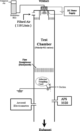
To investigate the uniformity of the aerosol deposit on the filter, a vibrating orifice monodisperse aerosol generator (VOMAG; model 3450, TSI Inc., St. Paul, MN) was used to generate Methylene blue (MB) particles with a count median diameter (CMD) of 3 μ m and geometric standard deviation (GSD) of about 1.05 which was measured by an Aerodynamic Particle Sizer (APS, model 3320, TSI, Inc.). To facilitate continuous operation of the generator for more than a few days consecutively, a pressure supply system for the liquid and a large solution reservoir was added to the VOMAG. The volumetric concentration of the solution being generated was selected to produce the desired CMD after the solvent evaporated from the droplets. MB was chosen as the challenge aerosol, because, in addition to stronger contrast to the background filter, the MB deposit can be examined visually for uniformity after exposure to water vapor. The aerosols were dried by filtered compressed air and then neutralized by inducing a charge equal and opposite to that of the spray charge, whereby a voltage applied to the dispersion-air-orifice plate induced a charge on the droplet stream emerging from the vibrating orifice (CitationReischl et al. 1977) as presented in. After that, the aerosols were passed through an aluminum honeycomb flow straightener. The MB particle number concentration in the testing chamber was about 30 particles/cm3. An aerosol electrometer (model 3068, TSI Inc.) was used to confirm the neutralization of particle charges in the testing chamber.
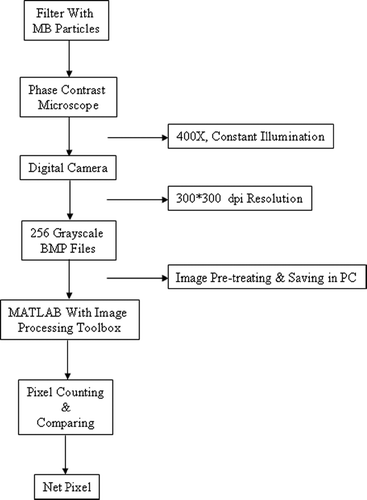
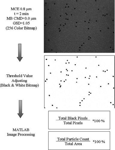
An asbestos filter sampler with a conductive cowl (Millipore Corp., Bedford, Mass.) and a 25 mm, 0.8 μ m pore size mixed cellulose ester (MCE) filter were used in the sampling. The MB particles were sampled on the surface of the filter, after being generated from the VOMAG. The filter with MB particle deposits were then examined under 400× of phase contrast microscope. Three counting protocols: equal distance (along the radial line), equal area (of the annular ring), and NIOSH Method 7400 were adopted and 10∼ 200 counting fields were selected manually. The counting results of three methods were then compared correspondingly using the same filter. Meanwhile, a digital camera (Flexcam®, model 999 0006-NPSCTA, VideoLab, Inc. Minneapolis, MN) with resolution set at 300 * 300 dpi (dots per inch) captured each selected field (as shown in the flow chart of). The captured image files were decolorized and converted into 256-grayscale bitmap (BMP) files, and then changed into two extremes (black and white) after the threshold value was manually set, as shown in. The MATLAB® language and image processing toolbox were programmed to count the fraction of black pixels (particles) compared to the total number of pixels in each counting field.
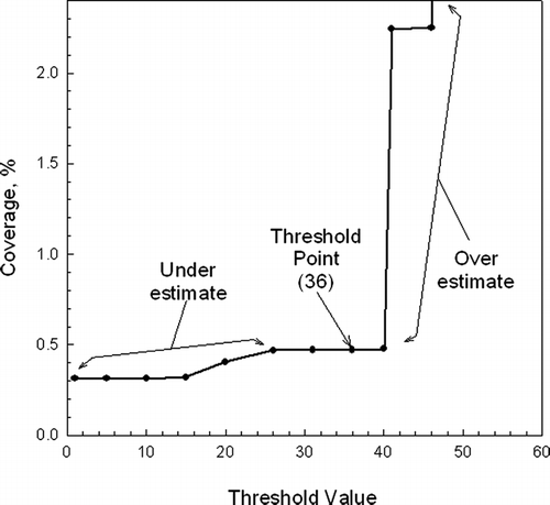
In the image-processing step, the procedure of changing the grayscale BMP files into black and white, a threshold value should be properly set. Here, the black pixels increased with increasing threshold value, and could cause the coverage of particles to be overestimated. However, the coverage of particles was underestimated when the threshold value was set too low. The accuracy of coverage depends on the pixels of each particle on a filter. Consequently, the proper threshold value was determined by trial and error, and was verified by comparing the coverage with the area calculated by particle number, since monodisperse aerosols were used in the present study. From, the coverage percentage remained about the same for threshold from 26 to 40. As the figure showed, when the value was below 26, the particle coverage was underestimated, as the total black pixels gradually decreased with decreasing threshold value. The decreasing threshold value resembles the edging area of an aerosol fading away. On the other hand, when the value was above 40, the particle coverage was apparently overestimated, as shown by the sharp increase in the total black pixels. The threshold value was set at 36 for all the image analyzing processes.
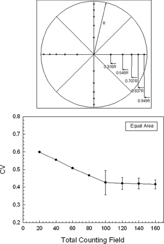
The counting method of equal distance was along each of the radial lines, and each counting field was selected at 0.5∼ 5 mm intervals. The maximum number of radial lines was four, and maximum counting fields were 200 with minimum intervals of 0.5 mm. The equal area counting was similar to that using the equal distance method. Along each of the four (90°) radial sectors, twenty counting fields from the 25 mm filters were selected in the middle of rings of equal area. The maximum number of radial sectors was 32 (11.25°), and the maximum number of counting fields was 160. Compared to the above equal distance and equal area methods, the NIOSH Method 7400 randomly select any sample of one-fourth of the filter and any counting fields of the filter quarter.
To avoid heavy overlapping of aerosol deposits, the sampling time was set at two minutes and the sampling flow rate was set at 5 L/min. In addition, to avoid unnecessary interference from electrostatic attraction, the sampler was electrically grounded during testing. The final step of the image analysis used the statistical methods, as discussed below.
Statistical Analysis
Following the image processing, all the data of the filter deposits can be separated into two: the black pixels (particles) and the whole pixels in each field. The “coverage” could be used to indicate the ratio of the field area occupied by the particles, and define as:
-
C: coverage (fraction of total viewing area occupied by particles).
-
P: pixels of all particles in a counting field.
-
F: total pixels in a counting field.
Notice that the particle number in a counting field can be used to replace the coverage, if the deposited particles are monodisperse, and vice versa.
With the coverage of each counting field calculated, the coefficient of variation (CV) could be used to indicate the variation of coverage among counting fields. The CV was given as follows:
-
CV: coefficient of variation.
-
σ: standard deviation of coverage of the particle area.
-
μ: the mean coverage of the particle area.
When the value of CV decreased, the variation of coverage among counting fields was small, indicating that each counting field had a similar particle deposition rate. However, the variation in coverage among counting fields increased with the value of CV. So it would be difficult to determine whether a deposition patterns was uniform or not by using the value of CV alone. In order to better define uniformity and make the indicator more universal, the uniformity was defined as the following equation.
-
U: uniformity of filter deposits.
The exponential of the negative CV value was a transformation to easily understand the uniformity of the filter deposits. According to Equation (Equation3), the U value has limited the variation in a small range from 0 to 1. Therefore, the more uniform is the filter deposits, the closer the uniformity value approaches 1.0. Meanwhile, the uniformity value approaching 0 is the case of least uniform.
The image processing method is a tedious and time consuming procedure since there are still many occasions in need of human decision. Therefore, the standard error (SE) of CV was evaluated by the Bootstrap re-sampling method (CitationMooney and Duval 1993; CitationHall 1992; CitationEfron and Tibshirani 1993). The Bootstrap method requires renumbering all the selected counting fields and randomly re-sampling the counting fields. For every re-sampling the CV of the coverage (of the re-sampled counting fields) is recalculated. The bootstrap method can then be expressed as follows.
-
SE
 : standard error of the CV.
 -
 : mean of CV.
 -
 : a random sample from the population of k particle coverage.
 -
b: bootstrap sample size (in the study was 100).
Using the macro function of Microsoft® Excel, the random selection of the counting fields was accomplished. Following the same technique, the uniformity could be evaluated for its standard error using the bootstrap method.
-
SE
 : standard error of U.
 -
 : mean of U.
RESULTS AND DISCUSSIONS
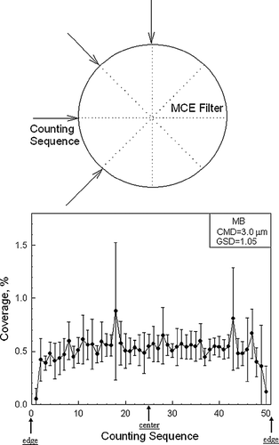
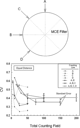
As illustrated in the upper plot of, the four random radial lines that separated the 25 mm filter into eight (45°) radial sectors were selected as the counting lines. Since the minimum counting interval with the equal distance method was set at 0.5 mm along a random radial line, the maximum number of counting fields along a random radial line was 50. Pooling the counting data from all of the observation fields on the four random radial lines (following the counting sequence), the particle coverage pattern was shown in the lower portion of. It can be seen that the particle coverage was lower near the edge of the filter, possibly because of the boundary effect of the airflow passing through the straight tubular cowl. Except for at the edge, particle coverage was relatively constant throughout the filter. However, some counting field had a higher standard deviation around the mean coverage, probably due to non-uniform filter deposits, or formation of the multiplets during aerosol generation and sampling. Particle overlapping may occur but was minimized to less than 5% according to the calculated cross-sectional area of the deposited particles.
The equal distance method was designed to representatively evaluate the whole filter for aerosol deposits, since the four random radial lines separate the entire filter into eight equal sectors. However, the equal distance method apparently placed too much emphasis on the central portion of the filter because all the counting radial lines pass through the center of the filter, as shown in. If not all four diameters (i.e., A, B, C, and D lines) were counted, the CV value might vary from 0.25 (B line) to 0.65 (A + B lines), depending on the total number of the counting field. In general, the CV decreased with increasing total counting field, as expected. The CV value approached 0.4 and tended to be constant when the counting fields exceeded 100. The standard error was calculated using Equation (Equation4). The CV value of three diameters (A, B, and C), represented by the shadow square connected by solid line, was lower than that of the total 200 counting field (A, B, C, and D), indicating that the D line must have a higher degree of non-uniformity, as shown in.
FIG. 6 The CV versus various counting lines and total counting fields using equal distance counting method.
The equal area counting method, as used in this study, should provide more representative results in evaluating the whole filter than the equal distance method, because same weighting was given to all the rings of identical surface area. However, as indicated in the lower portion of, the CV value was still dependent on the number of counting fields. It decreased with increased total counting fields and approached a constant of 0.4 when the counting fields exceeded 100. Furthermore, the standard error decreased with increasing counting fields. The extreme standard errors were found only when the total counting fields were smaller than 100. However, in order to better present and maintain an appropriate scale of the CV variation of equal area method in the graph, error bars for total counting fields smaller than 100 were not displayed in the plot.
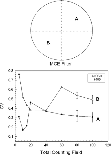
Since the conventional NIOSH Method 7400 was designed to randomly select any quarter of the filter for fiber counting, the CV values of counting fields on two filter quarters (A and B) are presented and compared in as a function of total counting field. As indicated by the fluctuation of the CV curves, the different parts of the filter apparently had different CV trends. The CV curves became more constant while the counting fields exceeded 100. Nevertheless, more counting fields need to be counted to prove that this behavior is typical. The NIOSH 7400 method seemed to be less statistically representative than the other two methods, based on the uniformity of filter deposits produced in the present study.
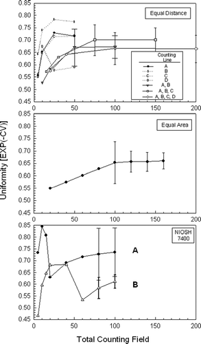
The uniformity (U) was used to describe the distribution of aerosol deposits on the filter, as shown in. The uniformity curves of the three methods were synchronous to their CV curves. As stated above, the more uniform are the filter deposits, the closer the uniformity value approached 1.0. In the equal distance method (the upper plot of), a few radial lines had good uniformity in a particular set of counting fields. However, these could be purely coincidental. In all three plots, the standard errors decreased with increasing counting fields, because of higher number counts.
CONCLUSIONS
In this work, uniformity (U) of filter deposits was studied and determined by using convenient statistical methods. In order to make the indicator more universal, the uniformity was further defined as the exponential of the negative CV (coefficient of variation) value which was a transformation for easily understanding the uniformity of the filter deposits. Three different methods (equal distance, equal area, and random on quarter) of counting aerosol deposits on the filter were performed and compared. The consistency of these counting protocols was examined using the CV, which could also be converted to uniformity through an exponential transformation. The advantage of adopting U is that it has a clear lower limit of 0 (least uniform) and upper boundary of 1.0 (most uniform). Using a MATLAB package and its image processing toolbox facilitated the determination of the CVs of the counting results. The variation of the counting results decreased with increasing number of counting fields, and this was true for all three counting protocols. Generally speaking, the value of uniformity approached a constant (0.65 in this work) when the counting fields exceeded 100 for the equal distance and equal area methods, although NIOSH Method 7400 did not provide a reliable statistical values.
In theory, the equal area method should be the most accurate (representative or non-biased) and precise counting protocol, because it treats all surface area equally. The equal distance method has the tendency to over-emphasize the central portion of the filter, because all counting lines cut through the center. The random on quarter method might lead to less representative results if the distribution of aerosol deposits is extremely distorted. There are other ways to obtain representative results, such as the randomly ordered method, which is also unbiased. However, it might require more counting fields to yield accurate results (CitationLeith and First 1976).
Factors that might contribute to the non-uniformity of aerosol deposition on filter such as sampling orientation, sampling flow, aerosol size distribution, particle charge and polarity, sampler charge and polarity, and the configuration of the samplers, are all likely to affect the aerosol deposition patterns on the filter, and therefore, change the variation of the counting results. The dynamic behaviors of compact particles, including transport and deposition is resemble those of fiber particles. However, there might be other factors, not considered in this work, causing errors when counting fibrous particles. Nevertheless, the development of uniformity (U) may provide a sound base and lead to a better fiber count method.
This study was supported by the National Science Council of Taiwan, through grant NSC 93-2211-E-002-034.
REFERENCES
- Baron , P. A. and Deye , G. J. 1990 . Electrostatic Effects in Asbestos Sampling I: Experimental Measurements . Am. Ind. Hyg. Assoc. J. , 51 ( 2 ) : 63 – 69 . [INFOTRIEVE] [CSA]
- Baron , P. A. , Chen , C. C. , Hemenway , D. R. and O'Shaughnessy , P. 1994 . Nonuniform Air Flow in Inlets: The Effect on Filter Deposits in the Fiber Sampling Cassette . Am. Ind. Hyg. Assoc. J. , 55 ( 8 ) : 722 – 732 . [INFOTRIEVE] [CSA]
- Baron , P. A. and Shulman , S. A. 1987 . Evaluation of the Magicscan Image Analyzer for Asbestos Fiber Counting . Am. Ind. Hyg. Assoc. J. , 48 ( 1 ) : 39 – 46 . [CSA]
- Chen , C. C. and Baron , P. A. 1996 . Aspiration Efficiency and Inlet Wall Deposition in the Fiber Sampling Cassette . Am. Ind. Hyg. Assoc. J. , 57 : 142 – 152 . [CSA]
- Donaldson , K. , Stone , V. , Gilmour , P. S. , Brown , D. M. and Macnee , W. 2000 . Ultrafine Particles: Mechanisms of Lung Injury . Philosophical Transactions: Mathematical, Physical & Engineering Sciences , 358 ( 1775 ) : 2741 – 2749 . [INFOTRIEVE] [CSA] [CROSSREF]
- Efron , B. and Tibshirani , R. J. 1993 . An Introduction to the Bootstrap , 45 – 59 . New York : Chapman & Hall .
- Hall , P. 1992 . The Bootstrap and Edgeworth Expansion , 1 – 35 . New York : Springer-Verlag .
- Hunsaker , H. A. , Buchan , R. M. , Keefe , T. J. and Marlatt , W. E. 1988 . Characterization of Asbestos Fiber Distribution on Membrane Filters from 25- and 37- Sampling Cassettes . Appl. Ind. Hyg. , 3 ( 10 ) : 284 – 290 . [CSA]
- Jenkins , S. L. , Feigley , C. E. and Jackson , K. L. 1992 . Fluorometric Analysis of the Uniformity of Deposition on Cassette Membrane Filters . Appl. Occup. Environ. Hyg. , 7 ( 10 ) : 665 – 671 . [CSA]
- Leith , D. and First , M. W. 1976 . Uncertainty in Particle Counting and Sizing Procedures . Am. Ind. Hyg. Assoc. J. , 37 ( 2 ) : 103 – 108 . [INFOTRIEVE] [CSA]
- Mooney , C. Z. and Duval , R. D. 1993 . Bootstrapping—A Nonparametric Approach to Statistical Inference , pp. 1 – 42 . London : SAGE Publications Ltd. .
- National Institute for Occupational Safety and Health . 1976 . Washington, D.C. : U.S. Department of Health Education and Welfare . Revised Recommended Asbestos Standard.
- National Institute for Occupational Safety and Health . 1994 . “ NIOSH Manual of Analytical Methods ” . In Fibers, Method 7400 Issue #2 (8/15/94) , Cincinnati, OH : DHHS (NIOSH) .
- Oberdörster , G. 2001 . Pulmonary Effects of Inhaled Ultrafine Particles, Int. Arch. . Occup. Environ. Health. , 74 : 1 – 8 . [CSA] [CROSSREF]
- Peters , A. , Wichmann , A. Tuch , T. 1997 . Respiratory Effects are Associated with the Number of Ultrafine Particles . Am. J. Respir. Care Med. , 155 : 1376 – 1383 . [CSA]
- Reischl , G. , John , W. and Devor , W. 1977 . Uniform Electrical Charging of Monodisperse Aerosols . J. Aerosol Sci. , 8 : 55 – 65 . [CSA] [CROSSREF]
- Vincent , J. H. 1989 . Aerosol Sampling: Science and Practice , New York : John Wiley & Sons .
