Abstract
A new deconvolution scheme is proposed to retrieve the true transfer function of differential mobility analyzers (DMAs) from tandem DMA (TDMA) experimental data. Apart from the existing methods in which the transfer function is represented as either a triangular or a Gaussian shape, the true DMA transfer function in the new scheme is represented by a piecewise linear function. The conjugate gradient optimization method is used to find the best fit between the calculated and experimental TDMA data. It is shown that the scheme is insensitive to experimental error and able to differentiate the shapes of DMA transfer functions for different particle sizes. The scheme is further applied to obtain the true transfer function of Nano-DMA (CitationChen et al. 1998).
INTRODUCTION
Differential mobility analyzers (DMAs) are powerful tools for studying particles in the submicron and nanometer diameter ranges. The tandem DMA (TDMA) experiment is commonly performed to calibrate the performance of a DMA, which is characterized by the transfer function (CitationKnutson et al. 1975). The experiment consists of two identical DMA columns and a particle number counter. In the experiment, a fixed voltage is applied on the first DMA to classify particles of a desired size. The voltage on the second DMA is varied over the entire applicable voltage range, and the particle concentration at the second DMA exit is measured with a particle counter and recorded at each varied voltage. The so-called TDMA data is obtained by normalizing the recorded particle concentration at the second DMA exit with that at the second DMA inlet at each varied voltage. The number concentrations of particles at the exits of the first and second DMAs, N 1 and N 2, can be expressed as:
A deconvolution scheme is thus needed to retrieve the DMA transfer function. All the existing deconvolution schemes, however, include presumed functional shapes for the DMA transfer function. The shape of the transfer function is often assumed to be either a triangle or a Gaussian shape (CitationHummes et al. 1996; CitationStratmann et al. 1997). From fundamental studies of DMAs (CitationStratmann et al. 1995; Stolzenberg 1988), the triangular-shaped transfer function is best suited for nondiffusive particles, and the Gaussian-shaped one is better for highly diffusive particles. These functional shapes can be characterized with two parameters, such as height and half-width (or standard deviation for the Gaussian-shaped function). During the deconvolution process, the parameters are iteratively adjusted so that the calculated convoluted data closely match with the experimental data. The presumption of the transfer function shape precludes the possibility of retrieving the real shape of transfer function from TDMA data. Other deconvolution schemes, providing the flexibility of adjusting the shape of DMA transfer function, are based on the theoretical diffusion transfer function (Stolzenberg 1988) the schemes take into the consideration particle loss and nonideal flow condition in DMAs by the inclusion of particle loss function (one unknown constant included in the given function) and a constant for the modification of theoretical particle broadening parameter in theoretical transfer function (Stolzenberg 1988). The scheme requires the scientific knowledge of DMA theory. Further, the implicit assumption in the schemes is that the DMA under the calibration is functioning properly, which may not always be the case during the new DMA development and DMA calibration phases. The objective of this study is, therefore, to develop a new deconvolution scheme, free from the limitation discussed and/or assumptions in existing schemes.
NEW DECONVOLUTION SCHEME FOR THE RETRIEVAL OF THE TRUE DMA TRANSFER FUNCTION
A new deconvolution scheme has been developed to retrieve the DMA true transfer function, without prior knowledge of the functional shape of the DMA transfer function. In the scheme, the entire electrical mobility window of the true transfer function is divided into N subsections, and a linear function is assumed in each subsection. The entire transfer function is thus represented with a piecewise linear function. Polynomials of high order or other functions can be assumed for each subsection if high accuracy and/or smoothness of the transfer function were desired. We selected the piecewise linear function because of its simplicity. The function in the i−th subsection with the electrical mobility window [Z p(i),Z p(i + 1)] was then defined as
The convoluted TDMA data can be numerically calculated from this representative transfer function, Ω, using Equation (Equation4) with initial guesses at the H i parameters. The optimal values of H i parameters in the representative transfer function can be obtained by matching the calculated TDMA data to the experimental data. In this study, 12 evenly spaced subsections were used in the deconvolution process (N = 12). Note that the number of subsections could be greater or less than 12 and the spacing in each subsection need not be even in this new scheme.
The scheme was implemented in MathCAD (MathSoft, Inc). The experimental data was input into MathCAD. The initial guess values for the unknown H i parameters were estimated using the nondiffusive transfer function. In this study, the optimization solver based on the conjugate gradient method (built in MathCAD) was used to adjust the H i parameters for the optimal solution (CitationPolak 1997). The least-square error was used as the criterion for the convergence of the iteration procedure:
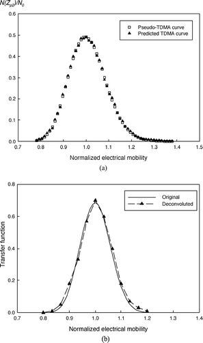
To test the scheme, pseudo-TDMA data were first numerically generated using Equation (Equation3) with the ideal triangular or diffusive transfer function (Stolzenburg 1988). The pseudo-TDMA data were then used as the experimental TDMA data and input into the new deconvolution scheme. The piecewise linear function was assumed in the scheme to represent the true DMA transfer function. shows the comparison between the pseudo-TDMA and predicted TDMA data after the optimization process was completed. The calculated data agree well with the pseudo-TDMA ones. shows the comparison between the DMA transfer function obtained by the new scheme and the triangular transfer function used to generate pseudo-TDMA data. As shown in the figure, the deconvoluted transfer function obtained by the new scheme reproduces the original DMA transfer function. The transfer function given by Stolzenburg (1988) was also used in this study to generate the pseudo-TDMA data. Particles of 11 nm diameter were assumed in the transfer function calculation. The generated pseudo-TDMA data were then introduced into the new scheme to test its ability to recover the original DMA transfer function. shows the comparison of the predicted TDMA data (output of the deconvolution scheme) with the pseudo-TDMA ones, such as the input of the deconvolution procedure. The two sets of TDMA data match well. shows the comparison between the deconvoluted piecewise linear transfer function and the original diffusive transfer function. The good agreement in this test demonstrates the ability of the new scheme to differentiate the shapes of transfer functions for different particle sizes.
FIG. 1 (a) Comparison of the pseudo-TDMA curve using the ideal triangular DMA transfer function and the predicted TDMA curve from the new deconvolution scheme; (b) comparison of the deconvoluted piecewise linear transfer function and the ideal triangular transfer function used to produce the pseudo-TDMA curve.
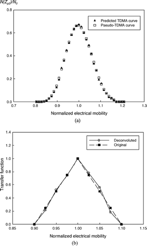
FIG. 2 (a) Comparison of the pseudo-TDMA curve produced using the diffusive transfer function given by Stolzenburg (1988) and the predicted TDMA curve from the new deconvolution scheme; (b) comparison of the deconvoluted piecewise linear transfer function and the diffusive transfer function used to produce the pseudo-TDMA data. The test particle size was 11 nm.
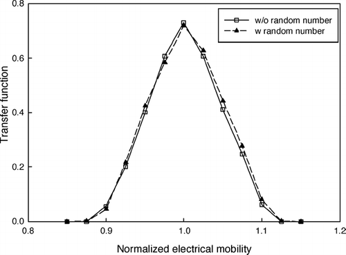
A sensitivity test was also performed to check the stability of the new scheme. Random errors were superimposed on the pseudo-TDMA data generated. To create artificial experimental errors, a random error percentage between –5% and 5% was produced using MathCAD. The 5% relative error is typically encountered when condensation particle counters (CPCs) are used as the particle concentration detector in TDMA experiments. A uniform error distribution was assumed in the pseudo-TDMA data. The resulting TMDA data (with the random errors) was then fed into the new scheme to retrieve the transfer function. shows the comparison between the original and deconvoluted transfer functions under the same convergence criteria used in the cases with error-free TDMA data. As evidenced, these two transfer functions are nearly identical. The calculated least-square error between two transfer functions in this case is about 1.8%, so the exercise demonstrates the stability of the new scheme.
FIG. 3 Comparison of the deconvoluted transfer function with the original transfer function used to produce the pseudo-TDMA data. In this case, random errors (up to 5%) were superimposed on the pseudo-TDMA data.
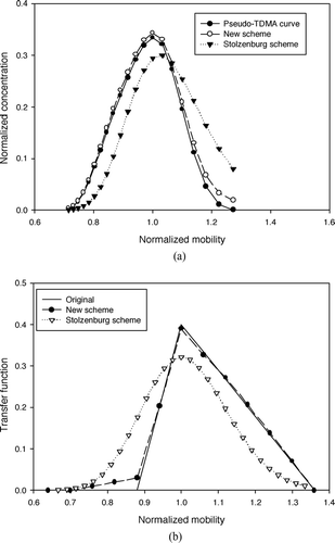
To demonstrate the superiority of the new scheme over existing ones, a skewed transfer function was used to generate pseudo-TMDA curve. The pseudo-TMDA data was then deconvoluted by using the new scheme and the one based on the theoretical diffusion transfer function. shows the comparison among the pseudo-TDMA and predicted TDMA data calculated by both schemes. The TDMA data calculated by the new scheme match well with the pseudo-TDMA curve while the scheme based on the theoretical diffusion transfer function fails to reproduce pseudo-TDMA curve. shows the comparison among the given skewed DMA transfer function used to generate pseudo-TDMA data, the transfer function given by the new scheme and that obtained by the scheme based on the theoretical diffusion transfer function. The test reveals the capability of the new scheme to retrieve the true transfer function of a DMA without preknowledge on the shape of the transfer function.
FIG. 4 (a) Comparison among the pseudo-TDMA data (created using Equation (Equation3) with predefined skewed transfer function), the TDMA curve calculated by the new deconvolution scheme, and that given by the scheme based on the diffusive transfer function (Stolzenburg scheme); (b) comparison among the predefined transfer function, the transfer function obtained by the new scheme, and that given by the scheme based on the diffusive transfer function.
APPLICATION OF THE NEW DECONVOLUTION SCHEME TO OBTAIN THE TRUE NANO-DMA TRANSFER FUNCTION
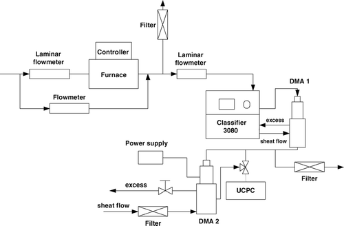
The new scheme was applied to obtain the true transfer function of Nano-DMA (CitationChen et al. 1998). The tandem DMA experiment shown in was performed to collect the TDMA data. Two commercial Nano-DMA columns (TSI model 3085) were used in the setup. Polydisperse silver particles were generated by the evaporation-condensation method (CitationScheibel et al. 1983). Silver powder was placed in the ceramic boat located near the middle position of the high-temperature furnace (Lindberg). Particles with peak diameters ranging from 6 to 50 nm were generated by controlling the furnace temperature, furnace tube flowrate, and dilution flowrate at the furnace tube exit. The voltage applied on the first DMA was fixed to classify test particles of desired sizes, and the classified particles were introduced into the second DMA. The voltage on the second DMA was varied during the experiment. The particle concentration downstream in the second DMA was detected by an ultrafine condensation particle counter (UCPC, TSI model 3025). The particle concentration at the exit of the second DMA was recorded as the function of the varied voltage. The TDMA data were obtained by normalizing the recorded downstream particle concentration with the upstream concentration of the second DMA. Two different sheath-to-aerosol flow ratios, 10 and 20, were used in the experiment, with the sheath flowrate kept at 15 lpm and aerosol flows of 1.5 and 0.75 lpm, respectively. Eight different particle sizes, namely, 6, 8, 10, 14, 20, 30, 40, and 50 nm, were tested at each sheath-and-aerosol flow combination. For each test particle size, the measurement was repeated five times, and the average was used as the TDMA data serving as the input for the new scheme.
FIG. 5 Schematic diagram of the tandem DMA experimental setup for collecting TDMA data to obtain the true transfer function of Nano-DMA.
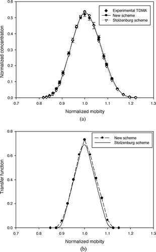
shows the comparison of experimental and convoluted TDMA data for the particle size of 20 nm at the flow ratio of 10. Convoluted TDMA data were produced by two deconvolution schemes, that is, the piecewise linear function scheme and the one based on the theoretical diffusion transfer function were used. Good agreement among three sets of TDMA data was obtained. shows the deconvoluted Nano-DMA transfer functions, obtained by two used schemes, for 20-nm particle diameter at the flowrate ratio of 10. Two deconvoluted transfer functions are nearly identical in the less electrical mobility regime (the left-hand side of the transfer function peak). Minor difference in the high electrical mobility regime of the transfer function (on the right-hand side) is detected.
FIG. 6 (a) Comparison of the experimental TDMA data and calculated TDMA curve from new and Stolzenburg deconvolution schemes; (b) the deconvoluted transfer functions of NanoDMA, obtained by piecewise linear function and Stolzenburg schemes. The particle size was 20 nm. The aerosol and sheath flow rates used were 1.5 and 15 lpm, respectively.
After obtaining the true transfer function, the area under the function curve can be integrated to evaluate particle loss in Nano-DMA. The area provides a measure of the transmission efficiency of Nano-DMA. shows the area of deconvoluted transfer function, normalized by that of nondiffusive transfer function, as a function of particle size at two different sheath-to-aerosol flow ratios, that is, 10 and 20. The nondiffusive transfer function assumes its shape of triangle given that the polydisperse aerosol flowrate is equal to the monodisperse aerosol sampling flowrate (CitationKnutson and Whitby 1975). Without considering the particle loss, the nodiffusive transfer function has an area of 0.1 at the flowrate ratio of 10 and 0.05 at the flowrate ratio of 20. In general, two normalized area curves (as a function of particle size) for two studied flowrate ratios are nearly identical. The normalized area at the flowrate ratio of 20 seems slightly larger than that at the flowrate ratio of 10, which is probably due to less particle loss at higher flow ratio as a result of more narrowed aerosol stream moving in Nano-DMA classification region.
FIG. 7 The true transfer function of Nano-DMA: (a) normalized area (b) resolution, defined as the ratio of the peak electrical mobility to the full width at half maximal height. The aerosol flow rates used were 1.5 and 0.75 lpm. With a fixed sheath flowrate of 15 lpm, the sheath-to-aerosol flow ratios were 10 and 20.
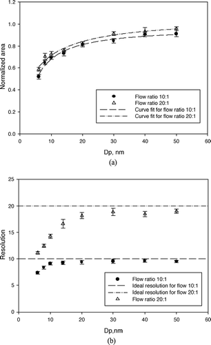
Another important parameter to evaluate the performance of a DMA is the sizing resolution, defined as the ratio of the peak electrical mobility to the full width at half maximum height. includes the sizing resolution of Nano-DMA as a function of particle size at two different flowrate ratios, that is, 10 and 20. The similar trends were observed for two studied flowrate ratios: the sizing resolution decreases with the decrease of particle size, due to the effect of particle Brownian broadening in Nano-DMA. The resolution approaches the theoretical values as the particle size increases.
CONCLUSION
A new deconvolution scheme has been developed to retrieve the true transfer function of a DMA from experimental TDMA data. The scheme represents the true DMA transfer function with a piecewise linear function. High-order functions, for example, second-order polynomials and cubic splines, could also be assumed to represent the true transfer function if high accuracy and/or smoothness of the deconvoluted function were desired. A numerical optimization method was utilized to find the best fit between the calculated and experimental TDMA data. In this study, the conjugated gradient method and least-square error criterion were used. Computer exercises demonstrate that the proposed scheme can be applied to recover the DMA transfer functions of different shapes. A sensitivity test of the new scheme reveals its stability when subjected to experimental error. The proposed scheme was also applied to obtain the true transfer function of Nano-DMA.
Acknowledgments
The authors are grateful for the support partially provided by the Department of Energy, Office of Science, Office of Biological and Environmental Research Management Science Program (EMSP) under project number 82,807 and the National Science Foundation (Grant No. CTS-0304649). The Oak Ridge National Laboratory is managed by UT-Battelle, LLC, for the U.S. Department of Energy under contract DE-AC05-00OR22725.
REFERENCES
- Chen , D.-R. , Pui , D. Y. H. , Hummes , D. , Fissan , H. , Quant , F. R. and Sem , G. J. 1998 . Design and Evaluation of a Nanometer Aerosol Differential Mobility Analyzer (Nano-DMA) . J. Aerosol Sci. Special Issue on Nanometer Particles , 29 : 497 – 509 .
- Hummes , D. , Stratmann , F. , Neumann , S. and Fissan , H. 1996 . Experimental Determination of the Transfer Function of a Differential Mobility Analyzer (DMA) in the Nanometer Size Range . Part. Syst. Charact , 13 : 327 – 332 . [CSA] [CROSSREF]
- Knutson , E. O. and Whitby , K. T. 1975 . Aerosol Classification by Electric Mobility: Apparatus, Theory, and Applications . J. Aerosol Sci. , 6 : 443 – 451 . [CSA] [CROSSREF]
- Polak , E. 1997 . Optimization: Algorithms and Consistent Approximations , New York : Springer-Verlag .
- Scheibel , H. G. and Porstendorfer , J. 1983 . Generation of Monodisperse Ag and NaCl Aerosol with Particle Diameters between 2 and 300 nm . J. Aerosol Sci. , 14 : 113 – 126 . [CSA] [CROSSREF]
- Stratmann , F. , Hummes , D. , Kauffeldt , T. and Fissan , H. 1995 . Convolution and Its Application to DMA Transfer Function Measurements . J. Aerosol Sci. , 26 : S143 – S144 . [CSA] [CROSSREF]
- Stratmann , F. , Kauffeldt , T. , Hummes , D. and Fissan , H. 1997 . Differential Electrical Mobility Analysis: A Theoretical Study . Aerosol Sci. and Tech. , 26 : 368 – 383 . [CSA]
- Stolzenburg , M. 1998 . Ph.D. dissertation Minneapolis, MN : An Ultrafine Aerosol Size Distribution Measuring System, Department of Mechanical Engineering, University of Minnesota .