A method has been developed to check the 50% cut-size values of cascade impactor stages. The method involves generating a broad-size, log-normally distributed aerosol that covers the range of 50% cut-sizes for the impactor being tested. The amount of deposit on each impaction plate is analyzed and a histogram of the resulting aerosol size distribution plotted, using the amount of aerosol collected on each impaction plate and the published values for the cut-sizes of the impactor in question. If the particle size distribution indicated by the histogram does not result in a log-normal distribution, one or more of the assumed cut-sizes of the impactor are in error. The incorrect cut-sizes of the impactor can then be adjusted until the curve is log-normal, and these adjusted cut-sizes are the correct values for the impactor stages.
INTRODUCTION
The traditional method of calibrating an impactor stage is to generate a monodisperse aerosol and pass the aerosol through the impactor. The amount of particles collected on the impactor stage and the amount of particles penetrating the stage is determined by a variety of methods depending upon the nature of the challenge aerosol. The fraction of the sum of these two quantities of particles that are collected on the impaction plate is the particle collection efficiency for that particle size and that stage (CitationMarple et al. 2003b). A number of these tests are run with a variety of monodisperse sizes to determine the particle collection efficiency curve of the stage from near 0% efficiency to near 100% efficiency. The value of the collection efficiency corresponding to 50% efficiency is defined as the cut-size of the stage.
The above method is labor intensive and rather time consuming since the quantity of particles collected for each test must be determined. Thus, other methods have been developed that are not so time consuming.
One of these methods is to generate monodisperse aerosols and measure the concentration of particles upstream and downstream of a stage with a real-time instrument (CitationKwon et al. 2003). The difference in these two concentrations can be used to calculate the particle collection efficiency for that particle size. Several monodisperse particle sizes are generated to define the particle collection efficiency curve for the stage. The major problem with this method is that interstage losses in the impactor and losses in the particle sampling lines leading to the real-time instrument counting the particles can cause a bias in the particle collection efficiency calculation.
An even faster method for determining the collection efficiency curve is to generate a polydisperse aerosol and measure the particle size distribution upstream and downstream of an impactor stage (CitationDemokritou et al. 2004). By comparing the concentration of corresponding particle sizes upstream and downstream of the stage, the entire collection efficiency curve can be generated in one test. The major problem with this technique is that the instrument measuring the concentration of the upstream and downstream aerosols may not be measuring the aerodynamic diameter of the particles in the same manner as an impactor, and again, the interstage losses cannot be determined.
In our laboratory, we have consistently used the time-consuming monodisperse challenge aerosol method for generating efficiency curves for impactor stages. We have found this is the most direct method for determining the particle collection efficiency curve. In addition, by washing out various parts of the impactor, interstage particle loss data can be obtained, as well as information on just where the losses are occurring. The major problem with this technique is that it is difficult to generate monodisperse aerosols at, or near, 1 μ m diameter. The lower limit of the Vibrating Orifice Aerosol Generator (VOAG, model 3450, TSI, Inc.), the generator used for generating super micron monodisperse aerosols, is traditionally about 1 μ m and the upper limit of the Differential Mobility Analyzer (DMA), the generator used for generating submicron aerosols, is typically about 0.5 μ m (CitationMarple et al. 1991). Thus, particle collection efficiency curves for impactor stages with cut-sizes in a range from about 0.5 to 1.0 μ m have not been as accurate as for impactor stages with cut-sizes above and below this range. Traditionally, monodisperse PSL particles have been used to calibrate in the particle range around 1 μ m. However, these particles are only available in a few distinct sizes and may not be near the cut-size of the impactor stage.
In this paper we explore the possibility of using a polydisperse aerosol of a log-normal size distribution with a mode at about 1 μ m diameter as a challenge aerosol to the entire cascade impactor instead of just one stage as is done in the above methods. The resulting size distribution of the deposited particles is then plotted using the assumed cut-sizes of the cascade impactor stages. If the resulting size distribution does not show a log-normal distribution, the cut-size(s) of any stage(s) that may be in question are adjusted until a log-normal distribution is obtained. It was assumed in this method that particles collected on the impaction plates could still be represented by a log-normal distribution, even after some particles may have been removed by interstage losses.
This method was applied to check the cut-size of the nominal 1.0 μ m cut-size stage of the Microorifice Uniform Deposit Impactor (MOUDI) (CitationMarple et al. 1991). In addition, through improved calibration equipment and techniques developed in our laboratory and described later in this paper, we are now able to generate monodisperse aerosols with the VOAG down to about 0.5 μ m. Thus, results of the polydisperse aerosol method to calibrate the 1.0 μ m cut-size MOUDI stage were then verified with the improved VOAG monodisperse aerosol method.
POLYDISPERSE CHALLENGE AEROSOL CALIBRATION METHOD
The polydisperse challenge aerosol calibration (PCAC) method is quite simple, in that a polydisperse aerosol is generated and sampled by the impactor under investigation. Since monodisperse particles larger and smaller than the 0.5 μ m to 1.0 μ m particle size range can be accurately generated by the VOAG and the DMA, the calibration of stages with cut-sizes above and below 1 μ m have been more accurately calibrated. The cut-size values of these stages serve as anchor points for the polydisperse aerosol calibration method. The cut-sizes of stages with cut-sizes of about 1 μ m are the ones with the highest degree of uncertainty, and thus the mode of the polydisperse aerosol should be at about 1.0 μ m. It should be noted that this method can be used equally well for any size of particle where the accuracy of the impactor stage cut-size is in doubt. However, the best results are obtained if the mode of the polydisperse aerosol is near to the uncertain cut-size stage.
After the polydisperse aerosol has been sampled by the cascade impactor, the quantity of the deposited particles on each stage must be determined. In our laboratory, fluorescent tagged aerosols are used, and the particles washed from the stage impaction plates in known volumes of wash water. The solutions are then analyzed with a fluorometer.
Once the quantity of the deposit collected at each stage has been determined, a histogram of the polydisperse aerosol is constructed, using the assumed cut-size values for the impactor stages, even the cut-size for the stage that is under suspicion of being in error. The cut-size of the stage in question is then adjusted by using higher or lower values until the histogram forms a smooth curve.
To provide a systematic procedure for determining this adjusted cut-size, the polydisperse aerosol was assumed to be log-normal and the commercial fitting program DistFit™ (CitationDistFit™, 2004) was used to determine the cut-size that gives the best fit as defined by the lowest χ2 value. An alternate method is to plot the size distribution as determined by the cascade impactor on a log-probability graph. The cut-size of the stage in question is then adjusted to give the best fit to a straight line on the log-probability graph.
TEST OF METHOD WITH AN IDEAL LOG-NORMAL AEROSOL AND A HYPOTHETICAL IDEAL CASCADE IMPACTOR
To test the PCAC method, a hypothetical ideal impactor (accurate cut-sizes for all stages) with stage cut-sizes of 18, 10, 5.6, 3.2, 1.8, 1.0, 0.56, 0.32, 0.18, and 0.10 μ m was used to sample an ideal log-normal aerosol with a geometric standard deviation (GSD) of 2.0. Three cases were tested with Mass Mean Aerodynamic Diameters (MMAD) of the log-normal distribution at 1.0, 1.34, and 1.17 μ m to determine if the position of the mode relative to stage cut-sizes affects the results. For a distribution with the MMAD = 1.0, the mode is at the cut-size of one of the stages, for a distribution with the MMAD = 1.34, the mode is at the log midpoint of the particle sizes collected on one stage, and for a distribution with the MMAD = 1.17, the mode falls midway between the first two cases on a log scale.
The test involved designating the amount of mass on each stage to be that dictated by the log-normal distribution and the cut-sizes of the stages. Then DistFit™ was applied to this data to observe if the original log-normal size distribution was obtained.
shows the results of this test for all three cases (note in the figure that D Aero refers to aerodynamic particle diameter). Note that in all three cases the original values of MMAD and the GSD was obtained and the χ2 values ranged from 1.61 × 10⁻⁸ to 2.88 × 10⁻¹⁵ depending where the mode of the distribution was in relation to the cut-sizes of the impactor. The smallest χ 2 value was obtained for the case where the midpoint of the particle sizes collected on one stage corresponded to the mode of the log-normal distribution as shown in .
FIG. 1 Ideal size distributions for (a) MMAD of 1.0 and GSD of 2.0, (b) MMAD of 1.34 and GSD of 2.0, and (c) MMAD of 1.17 and GSD of 2.0.
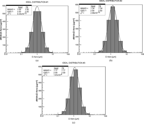
The conclusion of this test is that, by using DistFit™, the cascade impactor will return the size distribution of the challenge aerosol if the distribution is log-normal and if the cut-sizes of the impactor stages are accurately known.
TEST OF THE PCAC METHOD WITH A WELL CALIBRATED CASCADE IMPACTOR
The next test of the PCAC method involved using a real aerosol sampled by a real cascade impactor that had been carefully and accurately calibrated.
The cascade impactor was the Next Generation Pharmaceutical Impactor (NGI) (CitationMarple et al. 2003a) that had recently been calibrated by our laboratory (CitationMarple et al. 2003b, Citation2004) employing Good Laboratory Practice (GLP) procedures (21 CFR Part 58, 1987). In addition, the latest calibration procedures of our Particle Calibration Laboratory (PCL) were employed. These procedures included using small (3 μ m in diameter) orifices in the VOAG so that monodisperse particles in the submicron size range could be generated along with an impaction device at the exit of the VOAG to remove all multiplet particles resulting from coalescence of the primary particles from the air stream (CitationSiegford et al. 1994).
The polydisperse aerosol was generated by an Alltech atomizer adapted to the VOAG by replacing the piezoelectric vibrating orifice with the Alltech atomizer (model ELSD 500, Alltech Associates, Inc.). This resulted in a polydisperse aerosol of oleic acid particles with a mode at about 1.0 μ m. A fluorescent dye tracer was added to the oleic acid particles so that fluorometric analysis could be used to determine the quantity of particles collected on each stage.
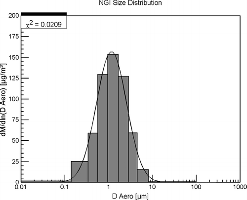
The polydisperse aerosol was electrostatic charge equilibrated using a Kr-85 radioactive source and drawn into the NGI at a flow rate of 30 L/min. The deposits on the impaction plates were then washed in known amounts of wash solution, which were then analyzed by a fluorometer (Aminico model J4–7439A, American Instruments Co.). The concentration of the fluorescent material is directly related to the mass of particles collected on each stage impaction plate. The particle size distribution was then plotted as a histogram (), and analyzed by DistFit™. The resulting log-normal distribution corresponding to the data from the NGI had a MMAD of 1.16 μ m and a GSD of 2.20. This log-normal distribution is plotted in as a solid line and visually shows a good fit to the histogram. In addition, a fit analysis between the histogram data and the log-normal distribution shows a fit with a χ2 value of 0.0209 using DistFit™. A χ2 value of 0.0209 indicates good agreement, especially since the size distribution of the polydisperse aerosol may not have been exactly log-normal.
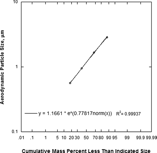
An alternate method of plotting the data on a log-probability graph and determining if the data produced a straight line, indicating a log-normal distribution was also investigated for the NGI data. The results, shown in , indicate that the data is a straight line with an R2 value of 0.99937.
The conclusion from testing the PCAC method with the NGI shows that (1) polydisperse aerosol from the Alltech atomizer is sufficiently log-normal for the evaluation of the cut-sizes of a cascade impactor, (2) if the impactor does have well defined cut-sizes, such as the NGI, the DistFit™ analysis will agree with a χ2 value of about 0.02, and (3) the fit of a linear line to the data on a log-probability graph should have an R2 value of at least 0.999.
APPLICATION OF PCAC METHOD TO THE MOUDI
At the time the MOUDI was initially calibrated in 1991 (CitationMarple et al. 1991), it was very difficult to generate monodisperse particles in the size range around 1 μ m. Thus, the cut-size of the stage with a nominal cut-size of 1.0 μ m has been suspect. Any error in this cut-size would not be apparent when sampling atmospheric aerosols, since 1.0 μ m falls in the saddle point between the large particle and accumulation particle modes (CitationWilson et al. 1977). However, it was observed that the histogram did not define a smooth particle distribution curve when using the MOUDI to sample industrial generated aerosols where there was no saddle point at 1.0 μ m. Thus, the PCAC method was applied to the MOUDI to check the cut-size of the 1.0 μ m stage.
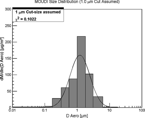
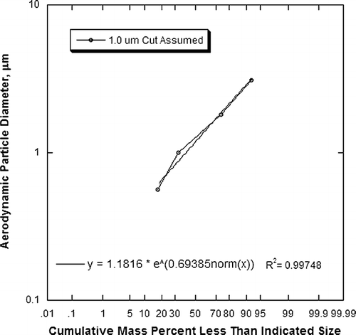
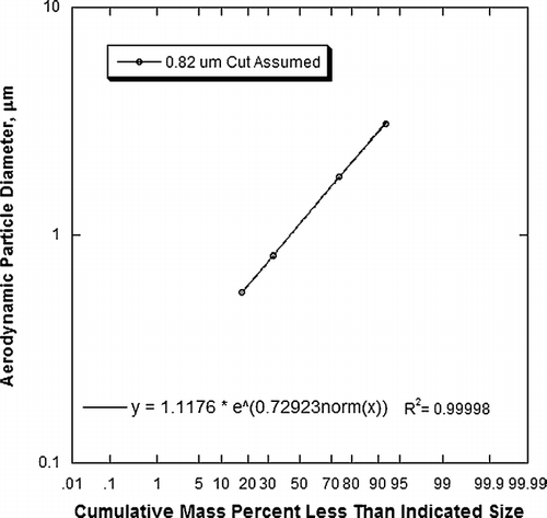
The same test procedure was applied to the MOUDI as described for the NGI. The histogram and resulting log-normal distribution from DistFit™ are shown in . This figure shows that visually the histogram does not define a smooth symmetrical curve and shows that there is a poor fit with a log-normal distribution, with a χ2 value of 0.1022. Also, as shown in , the data does not show a straight line on a log-probability graph, with an R2 value of 0.99748.
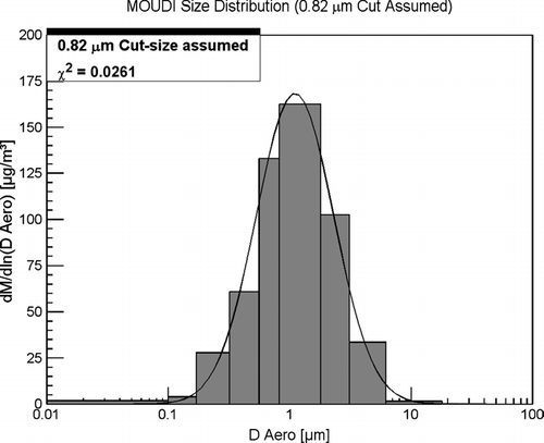
To determine the correct cut-size for the nominal 1.0 μ m MOUDI stage, different values for the cut-size were assumed and the fit to a log-normal size distribution checked with DistFit™ and the log-probability methods. The results are shown in . The assumed cut-size of the nominal 1.0 μ m stage was decreased until a minimum in the χ2 value from the DistFit™ method and the maximum value of R2 from the log-probability method were found. As shown in , this occurred for a cut-size of 0.82 μ m for the DistFit™ method and a cut-size between 0.82 and 0.83 μ m for the log-probability method for the nominal 1.0 μ m cut-size stage. These values for the cut-sizes are verified by the good visual match between the histogram and DistFit™ generated log-normal distribution curve in and the straight line observed on the log-probability graph of .
TABLE 1 Assumed cut-size and associated χ2 and R2 values for the nominal 1.0 μ m cut-size MOUDI stage
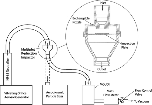
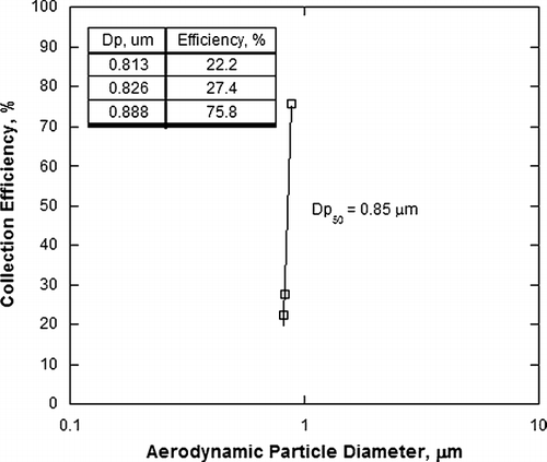
As a further check of the PCAC method, the nominal 1.0 μ m stage of the MOUDI was calibrated with monodisperse oleic acid particles using the latest technology of a well defined 3 μ m orifice in the VOAG and the use of a Multiplet Reduction Impactor (MRI) (CitationSiegford et al. 1994) to remove multiplets. An aerodynamic particle sizer (APS, model 3310, TSI Inc.) was utilized to ensure that the aerosol was monodisperse prior to sampling into the MOUDI. A schematic diagram of the test setup is given in . This resulted in a cut-size of 0.85 μ m as shown in . Since the challenge aerosol of the PCAC method may not have been exactly log-normal and since the finite number of stages in a cascade impactor provides for a histogram with bars of significant width, the value of the cut-size from the monodisperse calibration would be considered more accurate than the PACA method for determining the correct value of the cut-size. Thus, we find from this work that the cut-size of the nominal 1.0 μ m cut-size stage of the MOUDI is actually 0.85 μ m.
Finally, if 0.85 μ m is used as the d50 value in the Stokes number equation:
| ρ p | = |
is the particle density (g/cc) |
| Q | = |
is the volumetric flow rate (cc/ s) |
| C p | = |
is the Cunningham slip correction factor |
| n | = |
is the number of impactor stage nozzles |
| μ | = |
is the air viscosity (poise) |
| W | = |
is the impactor stage nozzle diameter (cm) |
This is significant since theoretical studies, verified by experimentation, predicts that the value of √ St50 should be 0.495, if the Reynolds number of the flow through a single round nozzle is in the range of 500 to 3,000 and the value of S/W is equal to or greater than 1.0, where S is the distance between the nozzle exit and the impaction plate and W is the nozzle diameter (CitationRader and Marple 1985). For the nominal 1.0 μ m size cut stage of this study, the value of the Reynolds number is 1,490 and S/W is 1.0. Thus, the calibrated value of √ St50 = 0.486 is within 2% of the predicted value of 0.495.
CONCLUSIONS
The polydisperse challenge aerosols calibration (PCAC) method can be used to provide a rapid check of the stage cut-sizes of a cascade impactor. This method is especially useful if there is one stage that is suspect of having an erroneous cut-size value. Usually, in such cases, the cut-sizes of the adjacent stages are well defined and serve as accurate anchor points for the PCAC method.
The PCAC method was shown to be applicable to impactor stage cut-size analysis by two tests. First the method was applied to a hypothetical perfect cascade impactor with specific cut-sizes sampling a hypothetically ideal log-normal distribution aerosol. The mode of the log-normal distribution was varied relative to the cut-sizes of the stages and the DistFit™ method showed little dependence on the position of the mode. The second tests involved sampling a real aerosol with a well characterized cascade impactor. Application of the DistFit™ method to the data showed agreement with a χ2 value of about 0.02.
When the PCAC method was applied to the MOUDI that had a suspected erroneous cut-size of the nominal 1.0 μ m stage, the result was the adjustment of the cut-size to 0.82 μ m with a DistFit™ method fit of χ2 value of 0.026. Calibration of this stage with monodisperse particles indicated a cut-size of 0.85 μ m, suggesting that the PCAC method accuracy is 3.5%.
Finally, of the two methods used to determine the cut-size of an impactor stage from the PCAC method, the DistFit™ method and the log-probability plot method, the DistFit™ method appears to be the most sensitive and would be the method of choice. However, if the DistFit™ program is not available, the log-probability plot method can be used with good accuracy.
REFERENCES
- Demokritou , P. , Lee , S. J. , Ferguson , S. T. and Koutrakis , P. 2004 . A Compact Multistage (Cascade) Impactor for the Characterization of Atmospheric Aerosols . J. Aerosol Sci. , 35 : 281 – 299 . [CSA]
- 2004 . Forest Lake, MN : Chimera Technologies Inc. . DistFitTM Users Guide V. 2.0
- Kwon , S. B. , Lim , K. S. , Jung , J. S. , Bae , G. N. and Lee , K. W. 2003 . Design and Calibration of a 5-stage Cascade Impactor (K-JIST Cascade Impactor) . J. Aerosol Sci. , 34 ( 3 ) : 289 – 300 . [CSA] [CROSSREF]
- Marple , V. A. , Roberts , D. L. , Romay , F. J. , Miller , N. C. , Truman , K. G. , Van Oort , M. , Olsson , B. , Holroyd , M. J. , Mitchell , J. P. and Hochrainer , D. 2003a . Next Generation Pharmaceutical Impactor (A New Impactor for Pharmaceutical Inhaler Testing)—Part I: Design . J. Aerosol Med. , 16 ( 3 ) : 283 – 299 . [INFOTRIEVE] [CSA] [CROSSREF]
- Marple , V. A. , Olson , B. A. , Santhanakrishnan , K. and Mitchell , J. P. 2003b . Next Generation Pharmaceutical Impactor (A New Impactor for Pharmaceutical Inhaler Testing)—Part II: Archival Calibration . J. Aerosol Medicine. , 16 ( 3 ) : 301 – 324 . [CSA] [CROSSREF]
- Marple , V. A. , Olson , B. A. , Santhanakrishnan , K. and Mitchell , J. P. 2004 . Next Generation Pharmaceutical Impactor (A New Impactor for Pharmaceutical Inhaler Testing)—Part III: Extension of Archival Calibration to 15 L/min . J. Aerosol Med. , 17 ( 4 ) : 335 – 343 . [INFOTRIEVE] [CSA] [CROSSREF]
- Marple , V. A. , Rubow , K. L. and Behm , S. M. 1991 . A Microorifice Uniform Deposit Impactor (MOUDI): Description, Calibration and Use . Aerosol Sci. Technol. , 14 : 434 – 446 . [CSA]
- Rader , D. J. and Marple , V. A. 1985 . Effect of UltraStokesian Drag and Particle Interception on Impactor Characteristics . Aerosol Sci. Technol. , 4 : 141 – 156 . [CSA]
- Siegford , K. L. , Marple , V. A. and Rubow , K. L. 1994 . A Multiplet Reduction Impactor for the Vibrating Orifice Aerosol Generator . J. Aerosol Sci. , 25 ( S1 ) : 113 – 114 . [CSA]
- US Code of Federal Regulations (CFR) . 1987 . Published in Federal Register , 52 ( 172 ) : 33768 – 33782 . 21 CFR Part 58[CSA]
- Wilson , W. E. , Spiller , L. L. , Ellestad , T. G. , Lamothe , P. J. , Dzubay , T. G. , Stevens , R. K. , Macias , E. S. , Fletcher , R. A. , Husar , J. D. , Husar , R. B. , Whitby , K. T. , Kittelson , D. B. and Cantrell , B. K. 1977 . General Motors Sulfate Dispersion Experiment: Summary of EPA Measurements . JAPCA , 27 : 46 – 51 . [CSA]
