Abstract
This article presents analytical and computational fluid-dynamics (CFD) solutions of the unsteady flow resulting from a horizontal circular disk moving downward at a constant velocity toward a horizontal floor seeded with spherical micro-particles, and the effect of this flow on particle detachment and levitation. The selected configuration is a simplification of numerous practical applications in which particle resuspension is important, for example a foot or an object impacting a dusty floor, or a squeeze film thrust bearing with particle contamination. The resulting radial and axial velocity field, coupled with a particle detachment model and the particle equations of motion were employed to compute particle trajectories in the gap. The CFD solutions were utilized to describe the high-speed radial wall jet and the vortices developing outside the disk and to explain their role in particle levitation and entrainment. It is shown that as the gap narrows the resulting radial velocity close to the disk perimeter is high enough to detach and levitate μ m-size particles, and that the vortices shed by the descending disk and its high-velocity radial wall jet create an upward convective motion that contributes to particle resuspension from the floor and entrainment in any far-field flow that might be present around the descending disk.
NOMENCLATURE
| C | = |
Cunningham correction factor for Knudsen effects |
| d | = |
particle diameter, m |
| f | = |
near-wall drag correction factor |
| F | = |
force on particle, N |
| h | = |
gap, m |
| P | = |
pressure, Pa |
| r | = |
radial coordinate, m |
| R | = |
disk radius, m |
| U | = |
mean radial velocity in gap, m/s |
| u | = |
radial velocity at a height z, m/s |
| u′ | = |
particle horizontal velocity, m/s |
| u* | = |
friction velocity in the r-direction, m/s |
| W | = |
disk velocity in the negative z-direction, m/s |
| w | = |
fluid velocity in the z-direction, m/s |
| w′ | = |
particle vertical velocity, m/s |
| z | = |
axial coordinate (normal to disk), m |
| μ | = |
fluid viscosity, Pa.s |
| ν | = |
fluid kinematic viscosity, m2/s |
| ρ | = |
fluid density, kg/m3 |
| ρ′ | = |
particle density, kg/m3 |
INTRODUCTION
Particle detachment from surfaces due to impacting objects is of interest in indoor environmental quality and industrial processes. Recent research in the so-called “personal dust cloud” suggest that human activities, such as walking and running, cause the resuspension of particulate matter (PM) attached to the floor, and for as much as a 60% increase in PM concentration in the human breathing zone compared with the room background concentration (CitationFerro et al. 2004). This is of particular concern for children and toddlers who spend a considerable amount of time close to the floor (CitationEisner et al. 2002). Other measurements indicate that walking in a room increases PM concentration by as much as 100% for particles larger than 5 μ m (CitationThatcher and Layton 1995). Several other studies (e.g., CitationAbt et al. 2000; CitationNazaroff 2004) also indicate that there is a significant increase in PM concentration in the 5–10 μ m size range after human walking. CitationSehmel (1980) showed that the effects of human activity are not confined to indoor spaces; resuspension rates were measured after subjects walked along asphalt roads. Understanding the mechanisms by which particles are detached then levitated from surfaces could help shed light on this phenomenon and develop methods to reduce its adverse impact on human health.
Particles adhere to smooth surfaces through the action of Van der Waals, electrostatic, and capillary forces (CitationSoltani and Ahmadi 1994). Even in the absence of electrostatic and capillary forces, the Van der Waals force, particularly for small particles (∼ 1 μ m), can be relatively high, requiring a commensurately high applied force to detach the particle. CitationEames and Dalziel (2000) suggested that particle detachment may be effected by two possible mechanisms: ballistic and hydrodynamic (aerodynamic). In the ballistic case, kinetic energy from an impacting body is transferred to the particle, dislodging it from the surface. A related case is that of a vibrating surface that imparts kinetic energy directly to the attached particle. In the hydrodynamic (or aerodynamic) mechanism, which is the subject of this paper, fluid forces acting on the particle, such as drag and lift, are the agents of detachment and levitation. Once detached by either mechanism, the particles are levitated from the surface and are entrained by the flow near the surface (CitationKildesø et al. 1999; CitationEames and Dalziel 2000).
CitationSoltani and Ahmadi (1994) and CitationIbrahim et al. (2003) have shown that very high velocities (10s of m/s) are required to detach small particles (∼ 1 μ m). Such velocities are not likely to be those associated with the free movement of an object, such as a foot, which moves at ∼ 1 m/s during a typical gait cycle (CitationGilchrist and Winter 1996). However, experiments show that human walking and running result in dust detachment and an elevated concentration of PM in the breathing zone of a moving person relative to the background room concentration (CitationFerro et al. 2004).
The aerodynamic mechanism is a major contributor to PM detachment, not because of the relatively modest speeds associated with the wake of the moving object (foot), but because of the high velocity jet ejected from the perimeter of the gap between the object and the floor as a result of air film squeezing under the object. This hypothesis is motivated by the analytical detachment models of CitationSoltani and Ahmadi (1994) and the experimental evidence of CitationIbrahim et al. (2003), which indicate that much higher shear velocities are needed to detach micro-particles from the surface under the approaching object. This is borne out by the work of Maedler and Koch (Citation1997, Citation1999), who used a simplified flow model to study particle resuspension caused by the radial wall jet resulting from an impacting disk and confirmed the important role the jet velocity played in particle resuspension outside the disk rim.
In the present work we investigate the unsteady flow velocity for a simulated moving object (e.g., a foot) approaching the floor at a constant velocity. We first develop an analytical model and obtain solutions for the unsteady axisymmetric laminar flow in the gap under a circular disk moving downward at constant velocity toward a parallel floor. Then we describe briefly the particle detachment and levitation models. This is subsequently coupled with the flow model, along with a Lagragian description of the particle motion to study the particle levitation and trajectories within the gap. Computational fluid dynamics (CFD) analysis is employed to simulate the high-speed wall jet issuing from the gap and its ability to detach and levitate particles outside the gap.
UNSTEADY FLUID MOTION IN THE GAP
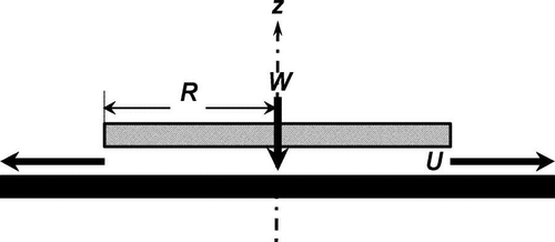
We consider a sparse distribution of smooth, spherical particles attached to a smooth horizontal surface over which a laminar shear flow, such as that present in a narrow gap between two flat plates is maintained (). To simulate the film squeezing effect under a descending object or a foot contacting the floor, we considered a round horizontal disk normal to the z-axis (). The disk is moving downward at a constant velocity W toward a horizontal smooth floor seeded with solid spherical particles.
The continuity equation for this axisymmetric arrangement is:
The flow at the Reynolds numbers expected in this case cannot be treated as a creeping flow with negligible inertia terms (Re ≪ 1) as is usually done in thin-film hydrodynamic lubrication (CitationSchlichting 1979), i.e., the inertia terms must be retained. With h ≪ R, the flow in the gap will be essentially parallel to the disk, i.e., w ≪ u and:
The continuity equation (Equation [Equation1]) can be integrated with respect to ζ to yield:
Following established procedures for similarity solutions in fluid dynamics (e.g., CitationSchlichting 1979), the above coordinate transformation (Equation [Equation8]) reduces Equation (Equation6) to:
The ζ -equation is obtained by equating the LHS of Equation (Equation12) to −β2:
Equation (Equation15) was solved numerically using an iterative method in which the values of −β2 and ϕ″ at ζ = 0 were iterated to satisfy the boundary conditions for u and w at z = 0 and z = h. The disk was assumed to have been moving at its uniform velocity from a sufficiently large initial gap and no account was made for the start-up transient associated with an impulsively started disk (the start-up transient was captured in the CFD analysis reported later in the paper). An example of the radial and vertical (axial) velocity profiles within the gap resulting from this numerical solution is shown in for r = 0.06 m, W = 0.5 m/s, and several gap values (time intervals during disk approach to the floor).
FIG. 2 Sample solutions of equation (Equation15) for r = 0.06 m and W = 0.5 m/s.
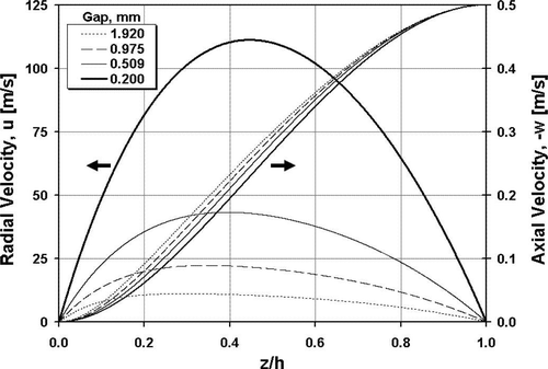
It can be seen that the radial velocity profile becomes more symmetrical and approaches the parabolic distribution corresponding to low Re h as the gap is progressively squeezed. The peak radial velocity in the gap reaches very high values (> 100 m/s) as the gap narrows to ∼0.2 mm, even for a modest disk velocity of 0.5 m/s. It can also be seen that the vertical velocity profiles depend only weakly on ζ h (i.e., Re h ).
Very close to the floor (i.e. for z ∼ particle diameter, d), w takes the simple form:
To facilitate the computation of particle trajectories, the numerical solutions for the velocity profiles were fitted to a 6th-order polynomial in z/h, whose coefficients were fitted to a 2nd-order polynomial in ζ h with an R 2 > 0.99 over the range 1 ≤ ζ h ≤ 10 :
TABLE 1 Coefficients a jk in Equation (Equation18)
PM DETACHMENT AND LEVITATION
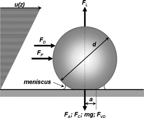
A particle attached to the floor in a horizontal shear flow experiences an adhesion force, F A , a capillary force, F C , a horizontal drag force, F D , a lift force, F L , and its own weight, mg ().
Because we are interested in particle levitation after detachment, we will focus especially on those forces that persist after detachment. The drag force includes both the viscous drag and an inertial drag due to flow acceleration (CitationCox and Cooker 2000; CitationChang and Maxy 1995). Also, in the presence of a pressure gradient, the particle will experience an additional force, F P , similar to buoyancy in the vertical direction, acting in the direction of decreasing pressure. Moreover, owing to the vertical down-flow velocity caused by the moving disk, the particle also experiences a downward force, F VD .
To analyze particle levitation after detachment, and its trajectory once levitated, we need to consider the forces acting on the particle in the vertical (z) and horizontal (r) directions, not only at the floor but also within the gap, where the velocity field changes with r, z, and t. CitationSoltani and Ahmadi (1994) provided a formula for fluid drag on an attached particle subjected to near-wall turbulent eddies that were treated as local stagnation flows. For laminar, accelerating flow, the drag force on a small particle is given by:
The drag coefficient, C D , is a function of the particle Reynolds number, Re′ = (u−u′)d/ν and is equal to 24/Re′ in the Stokes limit where Re′ ≪ 1. For particles with d ∼ 1 μ m, the Cunningham factor is typically < 1.2 in air at atmospheric pressure and temperature. The flow acceleration effect is proportional to the particle volume, which means that it would be significant relative to the viscous drag only for relatively large particles (d > 25 μ m), and very high accelerations. With the particle resting on the floor, the drag force will act above the particle center (), giving rise to an additional moment on the particle that must be taken into account in detachment calculations (CitationSoltani and Ahmadi 1994; CitationIbrahim et al. 2003). For a stationary small particle (d < 25 μm) attached to the floor, Re′ ≪ 1, and the viscous drag force is expressed by:
Because of the gap fluid's vertical downward velocity, w, created by the disk downward motion, the particle will experience a downward force given by:
It is customary to express the velocity at the center of an attached particle in terms of the velocity gradient at the wall, or alternatively, in terms of the friction velocity, u* = (τ o /ρ)1/2, with τ o representing the wall shear stress. Therefore, at the onset of levitation of a detached particle:
This formula shows that the critical levitation friction velocity for detached particles is independent of the particle size. For air at room temperature and silicon particles (ρ′/ρ = 1950), the critical friction velocity for levitation is 0.58 m/s. This indicates that unless W and h are such that the critical friction velocity for levitation is exceeded, even particles that would have been detached at this friction velocity (larger particles) will not be levitated within the gap.
CitationSoltani and Ahmadi (1994), and Ibrahim et al. (2004) presented several theories of detachment in shear flow. They conclude that the most likely detachment mechanism is particle rolling. To calculate the minimum velocity for particle rolling detachment, an aerodynamic moment sufficient to overcome the adhesion forces is needed. In this paper we adopted the Johnson-Kendall-Roberts (JKR) adhesion model following CitationSoltani and Ahmadi (1994), but included a correction factor, C PO < 1 to account for the effect of surface roughness, which was found to diminish the adhesion force (pull-off force) significantly (CitationCheng et al. 2002). The roughness effect may be somewhat offset by the capillary forces since capillary condensation tends to bridge the roughness asperities (CitationIsraelachvili 1992).
With laminar flow in the gap, detachment of small particles occurs when the friction velocity, u*, exceeds a critical value given by:
Only after the friction velocity exceeds the critical value will the particles begin to move (roll then lift off). For those particles that meet the detachment and levitation criteria (Equation Equation28and Equation Equation27), the vertical motion is governed by Equation (Equation24), which can be rewritten as:
Equation (Equation29) and Equation (Equation30), with appropriate expressions for f L as a function of ϵ, C D as a function of Re′, and f D as a function of z/d can be integrated numerically to obtain the particle trajectories in the gap after detachment, utilizing the gap flowfield computed in the previous section.
PARTICLE TRAJECTORIES
The computation of the fraction of particles initially under the disk that will exit through the gap at the disk outer radius cannot be inferred from detachment calculations alone. Unlike the flow outside the gap, where particles are free to travel upward once detached, the trajectories of particles under the disk are strongly influenced by presence of the descending disk and its associated unsteady flow. Therefore, detached particles may not always exit the gap during the short time it takes the disk to close the gap (∼2 ms for a gap of 1 mm and a disk velocity of 0.5 m/s). Calculation of the fraction and size distribution of particles exiting the gap requires that the trajectories of particles of various sizes, originating at various radial locations be determined.
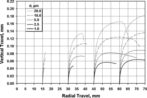
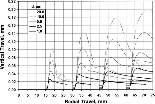
The particle equations of motion (Equation Equation29 and Equation Equation30) were integrated numerically using the previously computed gap velocity field to obtain particle trajectories. Sample results are shown in for four particle sizes originating at r = 0.015 m, r = 0.03 m, r = 0.045 m, and r = 0.06 m in an air gap squeezed by a disk approaching the floor at 0.5 m/s. The trajectories were terminated at an assumed disk outer radius of 0.075 m. In this example, both the particles and the floor were assumed to be silicon, and the factor C PO was taken arbitrarily as 0.25. Because this model assumes the flow to be incompressible, these results must be used with caution when the gap narrows to less than 0.2 mm to minimize the errors resulting from neglecting the effects of fluid compressibility, both due to the increased pressure in the squeezed film toward the disk center and due to the high-speed flow near the gap exit.Footnote 3
displays similar results for lighter particles (ρ′ = 1000 kg/m3) under a slower moving disk (W = 0.1 m/s). Under these conditions, larger particles experience trajectory oscillations as a result of lift reversal in the Poiseuille-like flow in the gap (shear reversal). The particle density and disk velocity have a noticeable effect on particle trajectories and, consequently, the fraction of particles that will exit the gap. With a slower disk and lighter particles, the particles have sufficient to time to be levitated and transported radially outward and not being driven back downward by the descending disk.
It can be seen that the particles are catapulted upward until they are eventually driven back down by the descending disk, and that only particles originating from locations near the outer radius of the disk are likely to exit the gap. At the gap perimeter, a high velocity wall jet flows radially outward and contributes to additional particle detachment and levitation outside the gap. With the flow unbounded by the disk on the top side, the upward vertical velocity component outside the gap is expected to play a significant role in levitation. The structure of the unsteady flow induced by this jet, and a discussion of its role in particle detachment and levitation are considered in the following section.
and show that not all trajectories extend to the disk outer radius. Only those particles whose trajectories extend to the disk outer radius and beyond will exit the gap at a given time. The fraction of particles of a given size leaving the gap can therefore be computed from the above analysis by determining the critical radius, r*(d), from which particles of diameter d would follow a trajectory that terminates at the disk outer radius, R, by the time the disk descends to a minimum gap, h m (0.2 mm in this analysis). Of the detached particles of diameter d covering the floor under the disk, only those in the area between r = r*(d) and r = R will exit the gap by the time the disk reaches h m ; the others will remain trapped inside the gap. By repeating this calculation for particles of various sizes distributed as a monolayer on the floor (no particle-particle interactions), it will be possible to determine the fraction of the total particles originally on the floor under the disk that would leave the gap, as well as the size distribution of those leaving the gap compared with the size distribution of the particles on the floor. These calculations will be reported in a future paper.
CFD ANALYSIS OF THE WALL JET OUTSIDE THE GAP
As mentioned in the introduction, CitationMaedler and Koch (1997) employed a highly simplified model of the radial wall jet issuing from the gap to study particle resuspension from an impacting object. In this section we present a more realistic, CFD-based model that can be used to compute particle detachment and levitation outside the disk gap. To this end, we solved the unsteady Navier-Stokes equations using a commercial CFD code. In this case, we included both the domain under a disk of 0.15 m diameter and that immediately outside the disk, extending to a radial distance of 0.12 m. A 2-D, axisymmetric assumption is a reasonable one for the flow under the disk and in the immediate vicinity outside the disk, as evidenced by flow visualization experiments reported by CitationSheth and colleagues (2005).
For this axisymmetric calculation, we used a second-order-accurate spatial scheme, and a first-order-accurate time integration scheme. Grid independence was achieved by solving the problem on different initial grid sizes until the velocity profiles were converged. To model the flow induced within and outside a narrowing gap, an unstructured, dynamic adaptive mesh was utilized. Two techniques for grid adaptation were employed to ensure accuracy of the results. First, after each time step, the disk moves towards the wall by a distance δ = W Δ t, and an automatic grid adaptation scheme within the CFD package re-meshed the entire computational domain. The time step Δ t was chosen as (h − δ o )/(2000 W), where δ o is the final gap height. This technique can be only used to compute and initially analyze the flow field induced by the disk. To compute the particle detachment, we need to compute the friction velocity, which requires accurate computations of the unsteady boundary layers. The above adaptation scheme does not ensure grid adaptation in the boundary layers. To guarantee adequate resolution, after every 50 time steps, another adaptation was performed near the walls and where the velocity gradients were large. Such a procedure guaranteed smooth distributions of the shear stress along the wall, and hence the friction velocity. For the computations of the disk approaching the wall at 0.5 m/s, the grids ranged from 28,000 cells at a gap of 10 mm at the beginning of disk motion to 130,000 cells at a gap of 0.5 mm.
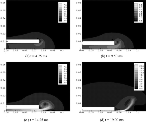
shows the unsteady velocity magnitude as the disk approaches the wall at 0.5 m/s for different time snapshots (note the different velocity scale in ). Initially the flow is at rest and the disk is set in motion impulsively. A starting vortex is generated at the tip of the disk as seen in . The flow is accelerated in the gap as shown by the analytical solution, is ejected as a high velocity radial wall jet from the gap, and turns around the disk perimeter. As the gap becomes narrower the jet velocity increases rapidly, and the vortex detaches from the disk. This vortex is similar in structure to vortices created by steady jets, where shear layers created by the jet entrain stagnant flow. The lateral wall jet velocity is mostly radial and unidirectional at this stage. The numerical value of the CFD-calculated U at r = R (75 mm) is within 0.5% of that calculated from Equation (Equation3). The vortex structure plays an important role in particle levitation and entrainment (after detachment) outside the gap. This has been confirmed in flow visualization experiments in a set-up similar to that considered in this paper (CitationSheth et al. 2005).
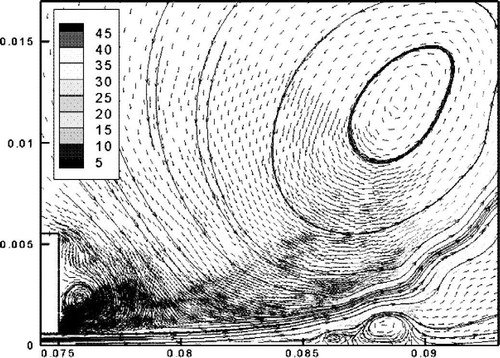
presents a snapshot of the velocity field and streamlines when the disk is within 0.5 mm of the floor. The jet structure is evident, but the flowfield outside the gap is very complex, with several recirculation bubbles and stagnation points. The effect of this complex flow on the friction velocity outside the gap must be taken into account in the computation of particle resuspension, which we will present later in this section.
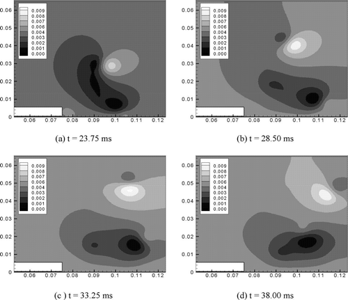
If the disk is brought to rest suddenly at a gap of 0.5 mm, an unsteady jet exiting the gap at a velocity in excess of 40 m/s expands radially outwards, and the velocities decay rapidly. Another vortex is created at the disk edge, rotating in the opposite direction of the starting vortex. Both vortex structures move with the unsteady jet and decay slowly as seen in . The numerical results also reveal the evolution of smaller and weaker vortices, which can contribute to PM entrainment and transport in the far-field flow (e.g., room ventilation or object wake).
Once the particles are detached and levitated, they could be easily entrained in and transported upward by the disk-induced flow (e.g., disk wake) and the far-field flows surrounding the descending object (e.g., forced ventilation currents in a room, or the free convection thermal plume around the human body). In the case of walking, the foot lift-off and the swing phase of the gait cycle are obvious contributors to the upward transport of detached PM, which results in a higher concentration of PM in the breathing zone of an active person than in the surrounding background. This gives rise to the so-called personal cloud (CitationFerro et al. 2004).
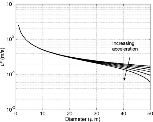
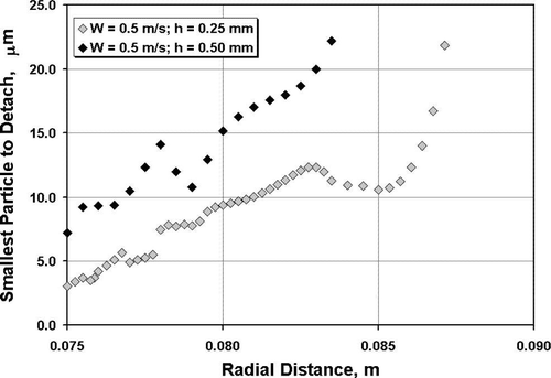
To compute the onset of detachment of particles of various sizes outside the gap, the friction velocity was obtained from the CFD results and used in conjunction with the detachment criterion (Equation Equation28) to estimate the minimum size of particles that can be detached at each radial location beyond the gap exit at R = 75 mm. We note that, unlike particles inside the gap, which may detach but not exit the gap to be entrained by the flow surrounding the disk, any particle that detaches outside the disk, where the flow is unbounded on the upward side, will be entrained in the flow surrounding the disk. depicts the minimum particle size that could be detached at various radial locations outside the disk for gaps of 0.5 mm and 0.25 mm and for the same detachment conditions used for computing the trajectories in . The irregularities in the trends shown in are due to the complex nature of the flow is the jet region outside the disk () as manifested by the recirculation bubbles and stagnation points.
It can be seen that the most effective zone of detachment is in the immediate vicinity of the gap exit where the velocity is highest (smallest size particles can be detached there). shows that particles smaller than ∼7 μm would not be detached by the radial wall jet at a gap of 0.5 mm, and that particles smaller than ∼3 μm would not be detached at a gap of 0.25 mm. The detachment zone for the 0.5 mm gap extends only to a radius of ∼83.5 mm (8.5 mm beyond gap exit), and that for the 0.25 mm gap (higher velocity) extends farther to a radial distance of ∼87 mm (12 mm beyond the gap exit). This trend is in agreement with that reported by CitationMaedler and Koch (1997). It is evident that the most important zone for detachment outside the gap is the zone in the immediate vicinity of the gap exit.
DISCUSSION AND CONCLUSIONS
The analysis presented in this paper elucidates the aerodynamic mechanism of particle detachment and levitation resulting from a descending disk. The disk in this case represents a simplified analog of a foot approaching a floor during the gait cycle, a flat-bottomed descending object, or a squeeze-film thrust bearing. Analytical solutions of the unsteady laminar Navier Stokes equations were obtained and used, in combination with particle detachment and transport models, to compute the trajectories of particles emanating from the floor under the descending disk. The particle detachment model accounts for the flow acceleration effect, which was found to be significant for larger particles but could be neglected for particles under 25 μ m in diameter.
The present model shows that very high velocities and shear rates are generated in the squeezed film that are sufficient to detach and levitate μ m-size particles. The model also shows that a high velocity flow is ejected from the gap perimeter and spreads radially outward as a decelerating wall jet. This jet plays a major role in particle detachment and levitation outside the gap.
It was found that particles emanating from floor locations close to the disk center are more difficult to detach. If levitated, these particles are eventually driven downward by the descending disk and are less likely to exit the rapidly closing gap. Particles emanating from locations close to disk perimeter are more easily detached, levitated and ejected with the radial jet exiting the gap, where they can be entrained in the outside flow. For lighter particles and low disk velocity (longer residence time in the gap), larger particles, which are easier to detach, are “catapulted” upward toward the disk and exhibit trajectory oscillations as they experience shear reversal when they cross the maximum velocity plane.
CFD solutions were obtained for the unsteady flow that develops inside the squeezed gap, and outside it. The CFD solutions show the evolution of the high velocity unsteady radial wall jet ejected from the gap. A strong vortex with a significant upward motion develops outside the gap. The jet, especially in the immediate vicinity of the gap exit, is the primary contributor to particle detachment outside the gap. The vortical structure and upward deflection of the flow are expected to be major contributors to the levitation of already detached particles outside the disk gap. Once levitated, detached particles can be entrained in whatever surrounding flow may exist around the descending object, such as the wake of the descending object, room ventilation, or, in the case of walking, the human thermal plume.
The detachment and levitation inside the gap are particularly important when the particles are attached to the descending object (e.g., tracked-in particles adhering to shoes). Under these conditions, gap effects represent the only mechanism for particles detachment and levitation. This is the subject of an ongoing study by the authors, in which the rate and size distribution of particles expelled from the gap and the effects of detachment and levitation in a dilating gap are also being investigated, using an extension of the approach described in this article.
Acknowledgments
The work described in this article was supported by the New York Office of Science, Technology and Academic Research (NYSTAR), and by the U.S. Environmental Protection Agency. The authors express their appreciation to Professors G. Ahmadi of Clarkson University, and M. Glauser and H. Higuchi of Syracuse University for their stimulating discussions.
Notes
1It can be shown that F P is < 2% of F D even for a 25 μ m particle in a 0.2 mm gap when W = 0.5 m/s.
2According to Saffman's analysis, Equation (Equation21) is valid only for ϵ ≪ 1, which is true very close to the wall, or when the particle velocity is nearly equal to the fluid's, i.e. small slip. While the latter condition is realizable for small particles in steady flows long after detachment, it may not apply in highly accelerated flows like those considered here, or near the maximum velocity in the gap. This does not affect detachment calculations, but would affect particle trajectory calculations, which included an expression for the f L factor based on CitationCherukat et al. (1999).
3The average radial velocity in a 0.2 mm gap with a 0.5 m/s disk velocity corresponds to a Mach number M ≅ 0.27 at r = 0.075 m. For a limiting M of 0.3, it is recommended that U = Wr/(2h) be kept under ∼100 m/s.
REFERENCES
- Abt , E. , Suh , H. , Catalano , P. and Koutrakis , P. 2000 . Relative Contribution of Outdoor and Indoor Particle Sources to Indoor Concentrations . Environ. Sci. Technol. , 34 : 3579 – 3587 .
- Chang , E. and Maxey , M. 1995 . Unsteady Flow about a Sphere at Low to Moderate Reynolds Number. Part 2. Accelerated Motion . J. Fluid Mech. , 303 : 133 – 153 .
- Cheng , W. , Brach , R. M. and Dunn , P. F. 2002 . Surface Roughness Effects on Microparticle Adhesion . J. Adhesion , 78 : 929 – 965 .
- Cherukat , P. , McLaughlin , J. B. and Dandy , D. S. 1999 . A computational Study of the Inertial Lift on a Sphere in a Linear Shear Flow Field . Int. J. Multiphase Flow , 25 : 15 – 33 .
- Cox , S. and Cooker , M. 2000 . Potential Flow Past a Sphere Touching a Tangent Plane . J. Engineer. Math. , 38 : 355 – 370 .
- Eames , I. and Dalziel , S. 2000 . Dust Resuspension by the Flow Around an Impacting Sphere . J. Fluid Mech. , 403 : 305 – 328 .
- Eisner , A. , Heist , D. , Drake , Z. , Mitchell , W. and Wiener , R. 2002 . On the Impact of the Human (Child) Microclimate on Passive Aerosol Monitor Performance . Aerosol Sci. Technol. , 36 : 803 – 813 .
- Ferro , A. , Kopperud , R. and Hildemann , L. 2004 . Source Strengths for Indoor Human Activities that Resuspend Particulate Matter . Environ. Sci. Technol. , 38 : 1759 – 1764 .
- Gilchrist , L. and Winter , D. 1996 . A Two-Part, Viscoelastic Foot Model for use in Gait Simulations . J. Biomechan. , 29 ( 6 ) : 795 – 798 .
- Goldman , A. J. , Cox , R. G. and Brenner , H. 1967 . Slow Viscous Motion of a Sphere Parallel to a Plane Wall—II Couette Flow . Chem. Engineer. Sci. , 22 : 653 – 660 .
- Ibrahim , A. , Dunn , P. and Brach , R. 2003 . Microparticle Detachment From Surfaces Exposed to Turbulent Air Flow: Controlled Experiments and Modeling . J. Aerosol Sci. , 34 : 765 – 782 .
- Israelachvili , J. 1992 . Intermolecular and Surface Forces, , 2nd ed. , London : Academic Press .
- Kildesø , J. , Vinzents , P. and Schneider , T. 1999 . A Simple Method for Measuring the Potential Resuspension of Dust From Carpets in the Indoor Environment . Textile Res. J. , 69 : 165 – 175 .
- Maedler , L. and Koch , W. 1997 . Particle Resuspension from Surfaces by Impacting Objects . J. Aerosol Sci. , 28 : S85 – S86 .
- Maedler , L. and Koch , W. 1999 . Particle Resuspension Burst from Dust Layers Induced by Impacting Objects . J. Aerosol. Sci. , 30 : S731 – S732 .
- McLaughlin , J. B. 1991 . Inertial Migration of a Small Sphere in a Linear Shear Flow . J. Fluid Mech. , 224 : 261 – 271 .
- Nazaroff , W. 2004 . Indoor Particle Dynamics . Indoor Air , 14 : 175 – 183 .
- O'Neill , M. E. 1968 . A Sphere in Contact with a Plane Wall in a Slow Linear Shear Flow . Chem. Engineer. Sci. , 23 : 1293 – 1298 .
- Saffman , P. G. 1965 . The Lift on a Small Spheres in a Slow Shear Flow . J. Fluid Mech. , 22 : 385 – 400 .
- Schlichting , H. 1979 . Boundary Layer Theory, , 7th ed. , New York : McGraw Hill .
- Sehmel , G. 1980 . Particle Resuspension: A Review . Environ. Internat. , 4 : 107 – 127 .
- Sheth , R. , Braud , C. , Higuchi , H. , Glauser , M. and Khalifa , H. E. Dust Resuspension due to Idealized Foot Motion . Presentation at the American Physical Society's Annual Meeting of the Division of Fluid Dynamics . November 20–22 2005 , Chicago .
- Soltani , M. and Ahmadi , G. 1994 . On Particle Adhesion and Removal Mechanisms in Turbulent Flows . J. Adhes. Sci. Technol. , 8 : 763 – 785 .
- Thatcher , T. and Layton , D. 1995 . Deposition, Resuspension, and Penetration of Particles Within a Residence . Atmos. Environ. , 29 : 1487 – 1497 .
